This document provides an overview of modeling and simulation approaches for an alkaline water electrolyzer. It describes the electrolysis process and reaction equations. A thermodynamic model is presented that calculates the reversible voltage and thermoneutral potential from changes in Gibbs free energy and enthalpy with temperature. The document also discusses sources of cell overpotential including activation, ohmic resistance, and gas bubble formation that increase the actual operating voltage above the minimum reversible value. Flow rates of hydrogen and oxygen produced are calculated from Faraday's laws using current and Faraday efficiency.
![1. Model Description
The process of water electrolysis described as the decomposition of water to its
elements Hydrogen and Oxygen. This process can be achieved by passing a DC
electric current in a based aquas solution of water. The reaction of water splitting is
𝐻𝐻2𝑂𝑂(𝑙𝑙) + 𝐸𝐸𝑙𝑙𝑙𝑙𝑙𝑙𝑙𝑙𝑙𝑙𝑙𝑙𝑙𝑙 𝐸𝐸𝐸𝐸𝐸𝐸𝐸𝐸𝐸𝐸𝐸𝐸
𝐸𝐸𝐸𝐸𝐸𝐸𝐸𝐸𝐸𝐸𝐸𝐸𝐸𝐸𝐸𝐸𝐸𝐸𝐸𝐸𝐸𝐸𝐸𝐸
�⎯⎯⎯⎯⎯⎯⎯� 𝐻𝐻2(𝑔𝑔) +
1
2
𝑂𝑂2(𝑔𝑔) (1.1)
The process must be achieved at minimum potential applied on the electrodes. The
required minimum or Reversable Voltage can be calculated from Gibbs energy
equation of water splitting. In an Alkaline Electrolyzer its common to use KOH or
NaOH as an aquas solution. The ions of Na+ and K+ as used to increase the process
of electrolysis by increasing the conductivity and ions of OH- used to increase the
reaction on the anode. The rection on each electrode can be described as
Anode 𝑂𝑂𝑂𝑂−(𝑎𝑎𝑎𝑎)
……………
�⎯⎯⎯⎯�
1
2
𝑂𝑂2(𝑔𝑔) + 𝐻𝐻2𝑂𝑂(𝑙𝑙) + 2𝑒𝑒−
(1.2)
Cathode 2𝐻𝐻2𝑂𝑂(𝑙𝑙) + 2𝑒𝑒−
……………
�⎯⎯⎯⎯� 𝐻𝐻2(𝑔𝑔) + 2𝑂𝑂𝑂𝑂−
(𝑎𝑎𝑎𝑎) (1.3)
Due to that alkaline solution the electrodes must be corrosion resistive and have
good electric conductivity. This could be achieved by using materials like Nickel,
Cobalt and Iron, See [1]. This could be illustrated in other sections.
1.1 Thermodynamic Model
The process of water electrolysis is the converting of electrical energy into chemical
energy. As both Oxygen and Hydrogen are available in the atmosphere, the chemical
energy can be calculated from the difference of enthalpy of formation ∆𝑓𝑓𝐻𝐻. The
change in chemical energy results a change in entropy. And as the change of
chemical energy is the change of enthalpy, the energy required is described by Gibbs
Equation.
ΔG = ΔH − TΔS (1.4)
ΔG = −Δ𝑓𝑓𝐺𝐺𝐻𝐻2𝑂𝑂(𝑙𝑙)
◦
= 237.1 𝑘𝑘𝑘𝑘/𝑚𝑚𝑚𝑚𝑚𝑚
ΔH = −Δ𝑓𝑓𝐻𝐻𝐻𝐻2𝑂𝑂(𝑙𝑙)
◦
= 285.8 𝑘𝑘𝑘𝑘/𝑚𝑚𝑚𝑚𝑚𝑚
The enthalpy of formation of both Hydrogen and Oxygen is zero, but water at the
conditions in Table 1.1 has an enthalpy value.
As water splitting increase entropy through the formation of gas, the TΔS term is
positive and contributes towards making the reaction progress more easily as it](https://image.slidesharecdn.com/modellingandsimulationapproach-221213055126-32e5343d/75/Modelling-and-simulation-approach-pdf-2-2048.jpg)
![decreases the Gibbs free energy. Therefore, the cost in energy supplied as work
required to drive the reaction is less than the energy available by combustion of
hydrogen. This enables water electrolysis to operate at electrical efficiencies above
100%.
Although rarely feasible in practice for alkaline systems due to kinetics, it is
practically possible at high temperatures with free heat energy available. That a fuel
cell or combustion process cannot convert back all the energy available in hydrogen
into work or electrical energy is a different aspect.
Fuel cells suffer the same entropy-driven energy penalty and is also kinetically
limited, whereas combustion processes are limited by the Carnot efficiency, See[2].
Table 1.1.1 Thermodynamic quantities at standard temperature and pressure
(STP), T = 298.15 K, p = 1 bar.
𝚫𝚫𝒇𝒇𝑯𝑯°
𝒌𝒌𝒌𝒌/𝒎𝒎𝒎𝒎𝒎𝒎
𝚫𝚫𝒇𝒇𝑮𝑮°
𝒌𝒌𝒌𝒌/𝒎𝒎𝒎𝒎𝒎𝒎
𝑺𝑺°
𝑱𝑱/𝒎𝒎𝒎𝒎𝒎𝒎. 𝒌𝒌
𝑪𝑪𝒑𝒑
°
𝑱𝑱/𝒎𝒎𝒎𝒎𝒎𝒎. 𝒌𝒌
𝑯𝑯𝟐𝟐 0 0 130.7 28.8
𝑶𝑶𝟐𝟐 0 0 205.2 29.4
𝑯𝑯𝟐𝟐𝑶𝑶(𝒍𝒍) -285.8 -237.1 70 75.3
𝑯𝑯𝟐𝟐𝑶𝑶(𝒈𝒈) -241.8 -228.6 188.8 33.6
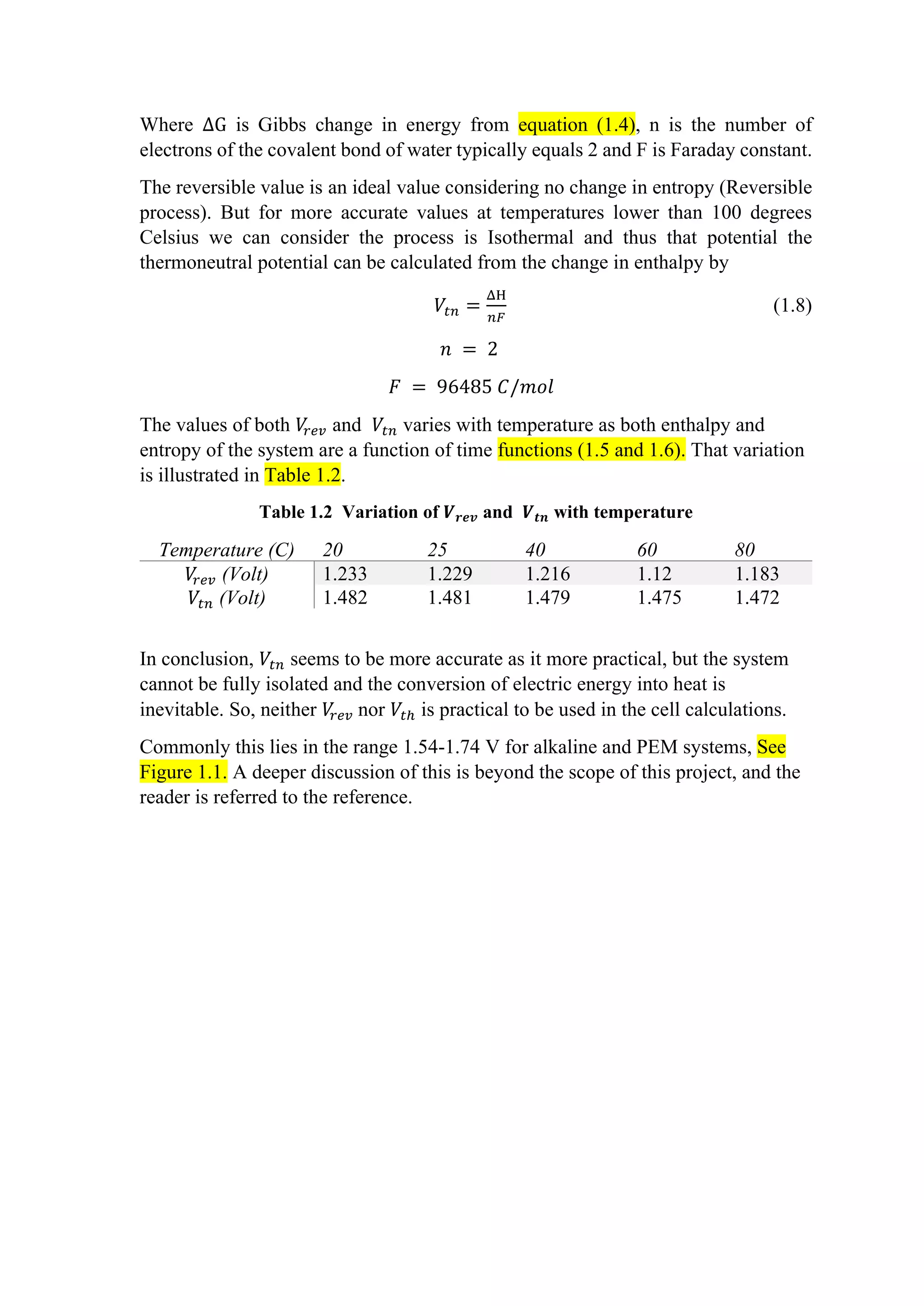
1.1.1 Temperature dependence
Increasing the temperature effects on the chemical equilibrium of the system. That
equilibrium is calculated by Gibbs equation. The change in enthalpy and molar
change in entropy is a function of both temperature and heat capacity. At operating
temperature below 100 𝐶𝐶 the variation of heat capacity can be assumed to be
constant. That temperature dependance can be described as
H(T) = 𝐻𝐻◦
+ ∫ 𝐶𝐶𝑝𝑝(𝑇𝑇)𝑑𝑑𝑑𝑑 ≈
𝑇𝑇
𝑇𝑇° 𝐻𝐻◦
+ 𝐶𝐶𝑝𝑝∆𝑇𝑇 (1.5)
S(T) = 𝑆𝑆◦
+ ∫
𝐶𝐶𝑝𝑝(𝑇𝑇)
𝑇𝑇
𝑑𝑑𝑑𝑑 ≈
𝑇𝑇
𝑇𝑇° 𝑆𝑆◦
+ 𝐶𝐶𝑝𝑝 ln
𝑇𝑇
𝑇𝑇°
(1.6)
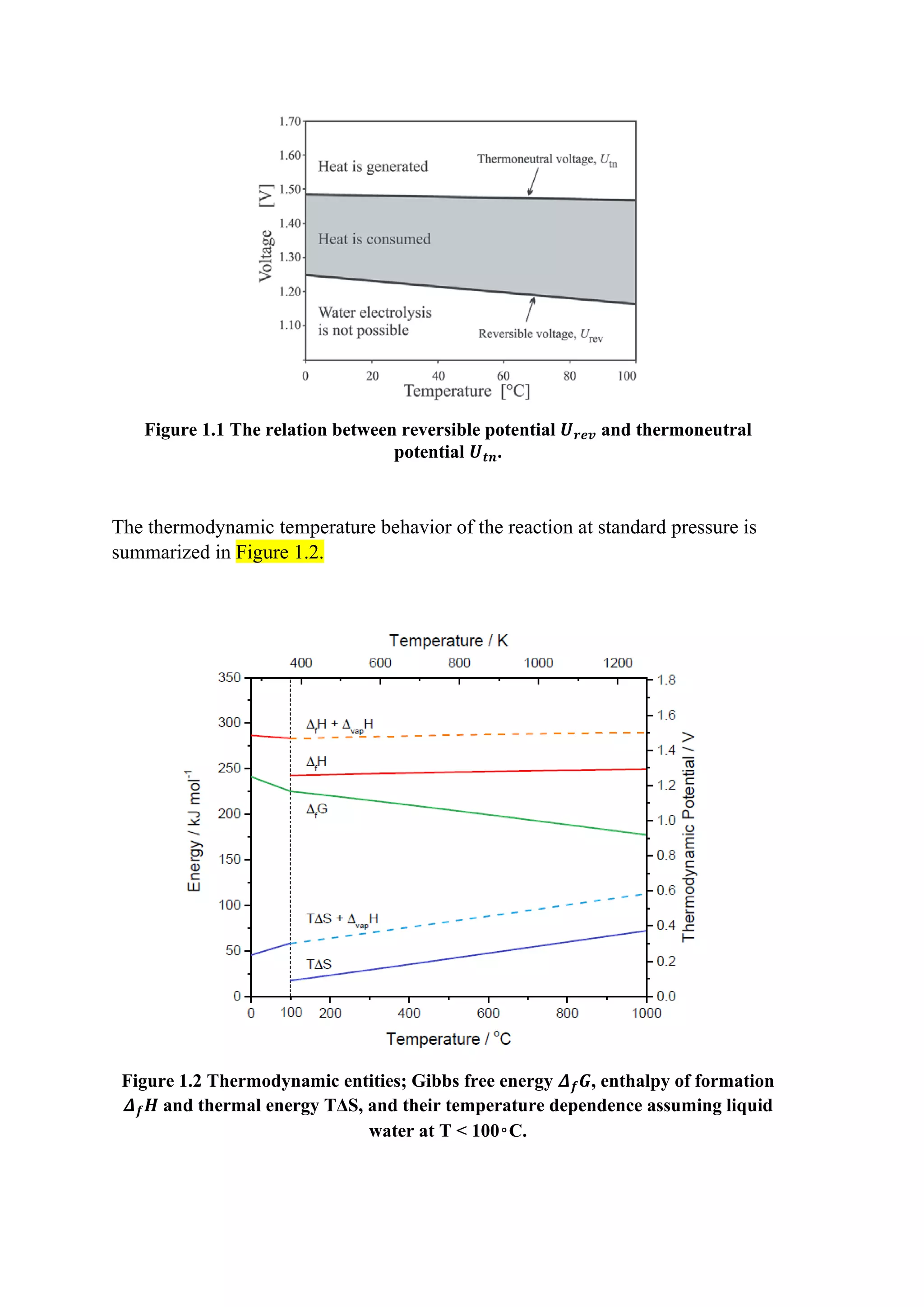
1.2 Electromechanical Model
1.2.1 Reversible Potential
The electromechanical reversible potential which is the minimum applied potential
to split water is calculated by the equation
𝑉𝑉
𝑟𝑟𝑟𝑟𝑟𝑟 =
ΔG
𝑛𝑛𝑛𝑛
(1.7)](https://image.slidesharecdn.com/modellingandsimulationapproach-221213055126-32e5343d/75/Modelling-and-simulation-approach-pdf-3-2048.jpg)
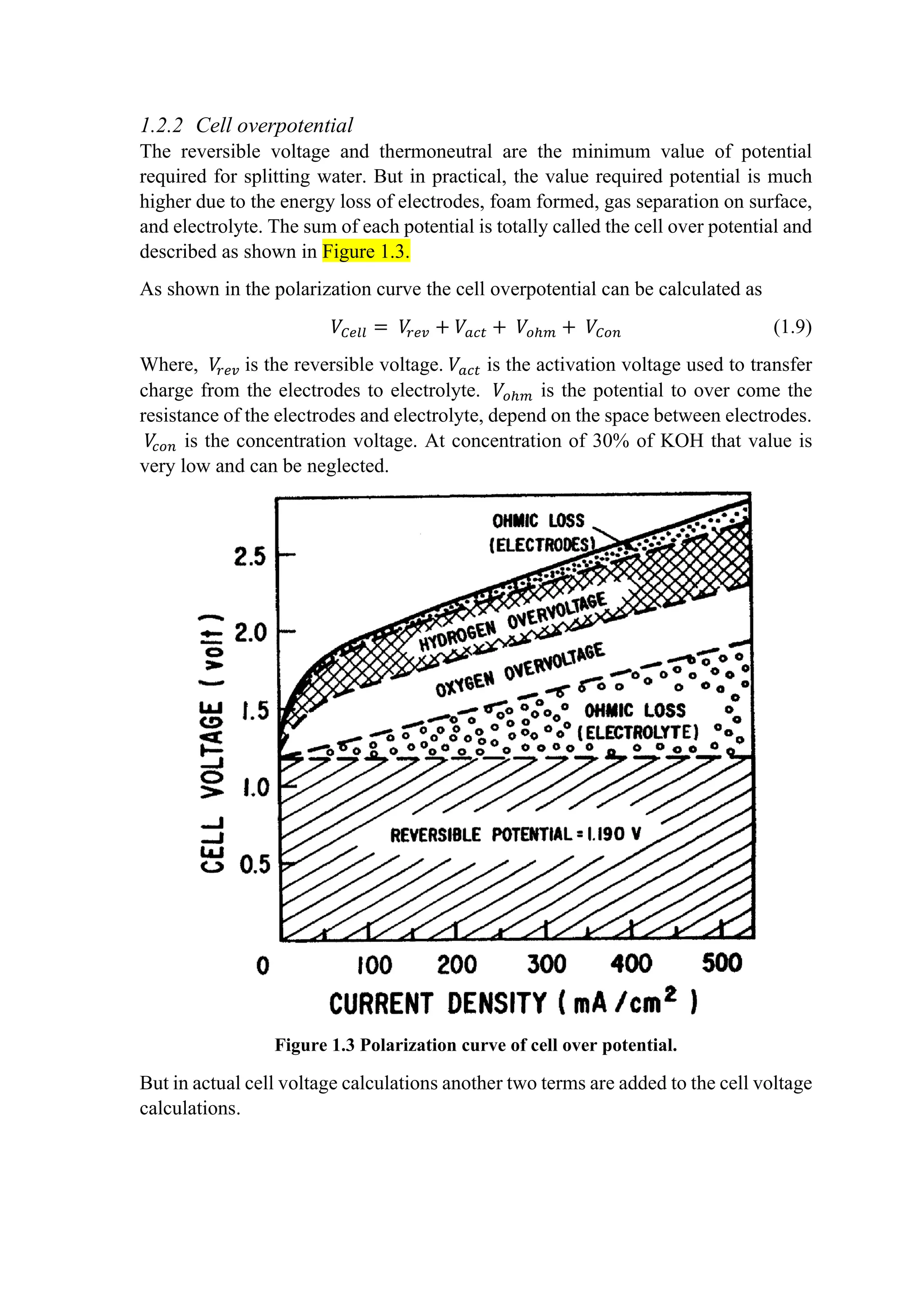
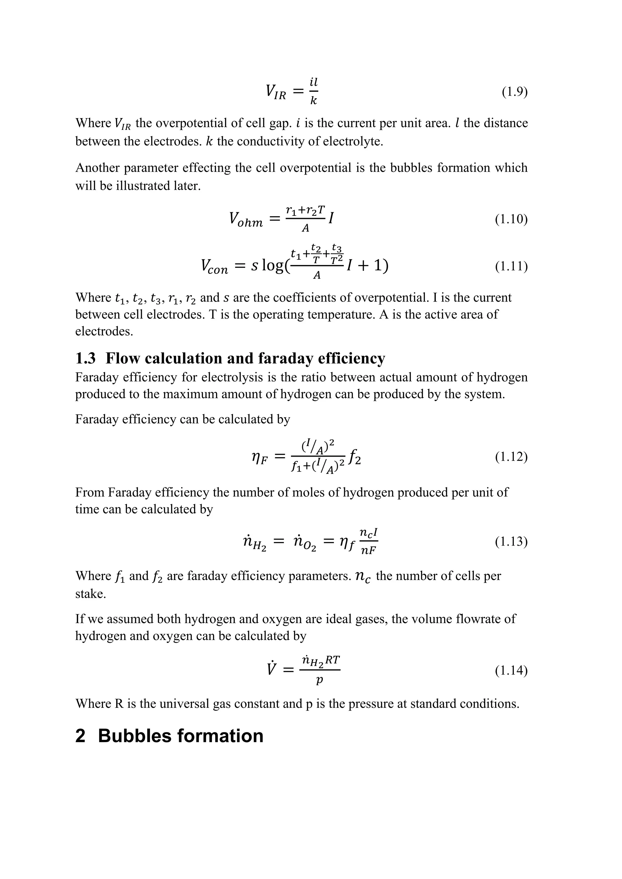
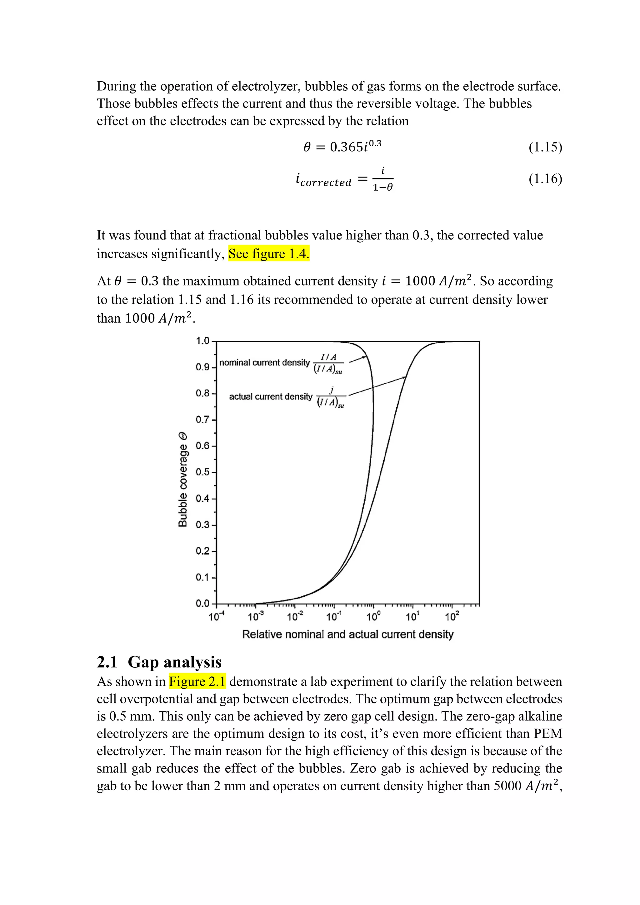
![See [3,4,5]. This high current density at conventional designs is not efficient. Zero
gab design is out of scope for this project.
Figure 2.1 A plot of cell voltage against the gap between electrodes.
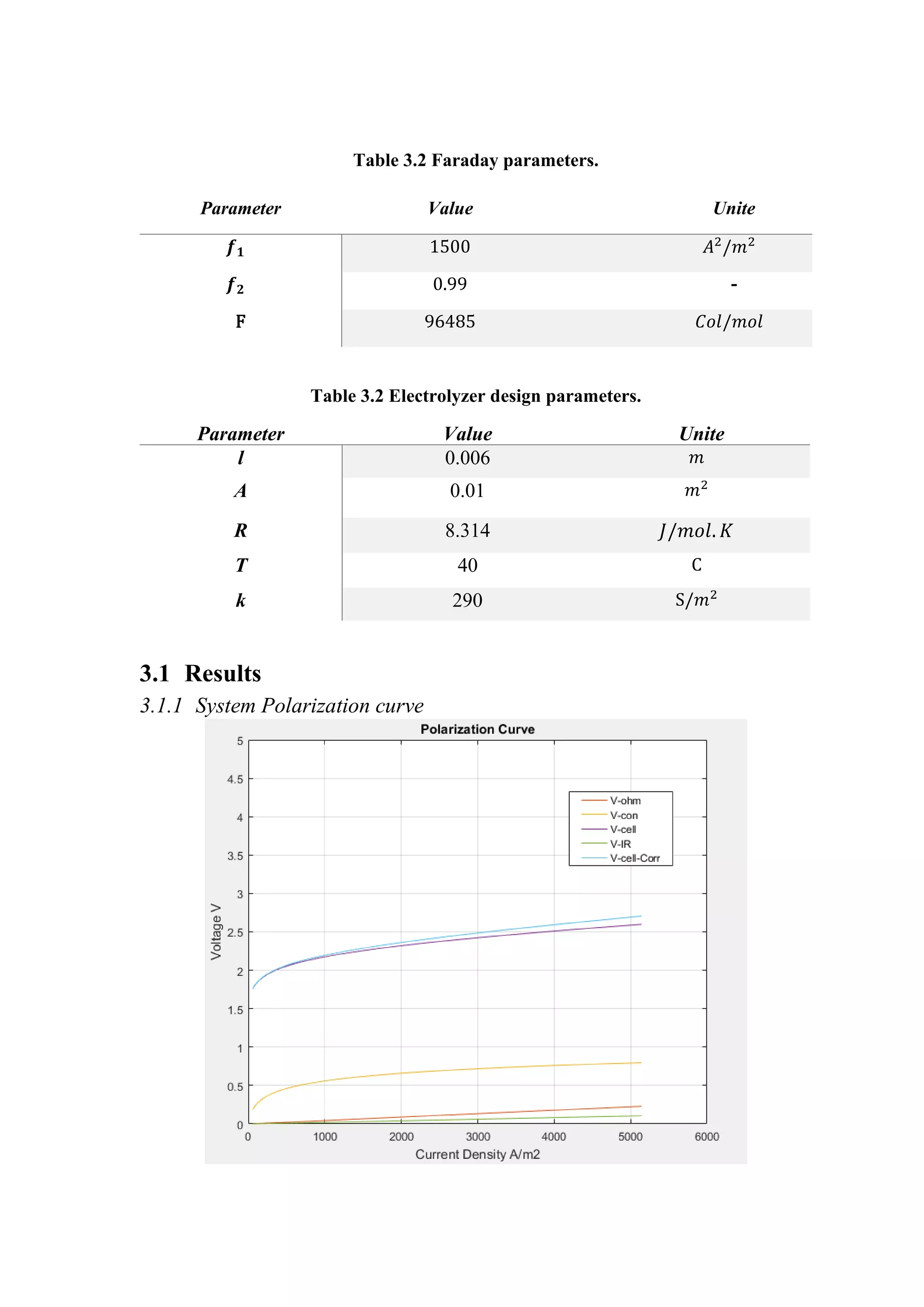
3 Simulation and results
For the system we designed we take consideration of the effect increasing of current
density and bubbles formation. So, our system operates on 800 𝐴𝐴/𝑚𝑚2
.
The coefficients of over potential are lab experimental parameters. There are many
models of those parameters, but the model demonstrated in Table 3.1 and Table 3.2
is more common used.
Table 3.1 Polarization curve parameters.
I-V Curve Parameters Value Unite
𝑟𝑟1 4.45153 𝑒𝑒 − 5 Ω𝑚𝑚2
𝑟𝑟2 6.88874 𝑒𝑒 − 9 Ω𝑚𝑚2
/𝐶𝐶
𝑠𝑠 0.33824 V
𝑡𝑡1 −0.01539 𝑚𝑚2
/𝐴𝐴
𝑡𝑡2 2.00181 𝑚𝑚2
𝐶𝐶/𝐴𝐴
𝑡𝑡3 15.24178 𝑚𝑚2
𝐶𝐶2
/𝐴𝐴](https://image.slidesharecdn.com/modellingandsimulationapproach-221213055126-32e5343d/75/Modelling-and-simulation-approach-pdf-9-2048.jpg)
![3.1.2 System Power Consumption
4 References
[1] Ulleberg O., (2003), “Modeling of advanced alkaline electrolyzers: a system
simulation approach”, Institute for Energy Technology.
[2] Kraglund M. R., (2017), “Alkaline membrane water electrolysis with non-
noble catalysts”, Department of Energy Conversion and Storage, Technical
University of Denmark.
[3] Phillips R., Dunnil C., (2016), “Zero gap alkaline electrolysis cell design
for renewable energy storage as hydrogen gas”, The Royal Society of
Chemistry.
[4] Vogt H., (2012), “The actual current density of gas-evolving electrodes—
Notes on the bubble coverage”, Electrochemical Acta.
[5] Nagai N., (2003), “Existence of optimum space between electrodes on
hydrogen production by water electrolysis”, International Journal of
Hydrogen Energy.](https://image.slidesharecdn.com/modellingandsimulationapproach-221213055126-32e5343d/75/Modelling-and-simulation-approach-pdf-11-2048.jpg)


