Download as PDF, PPTX


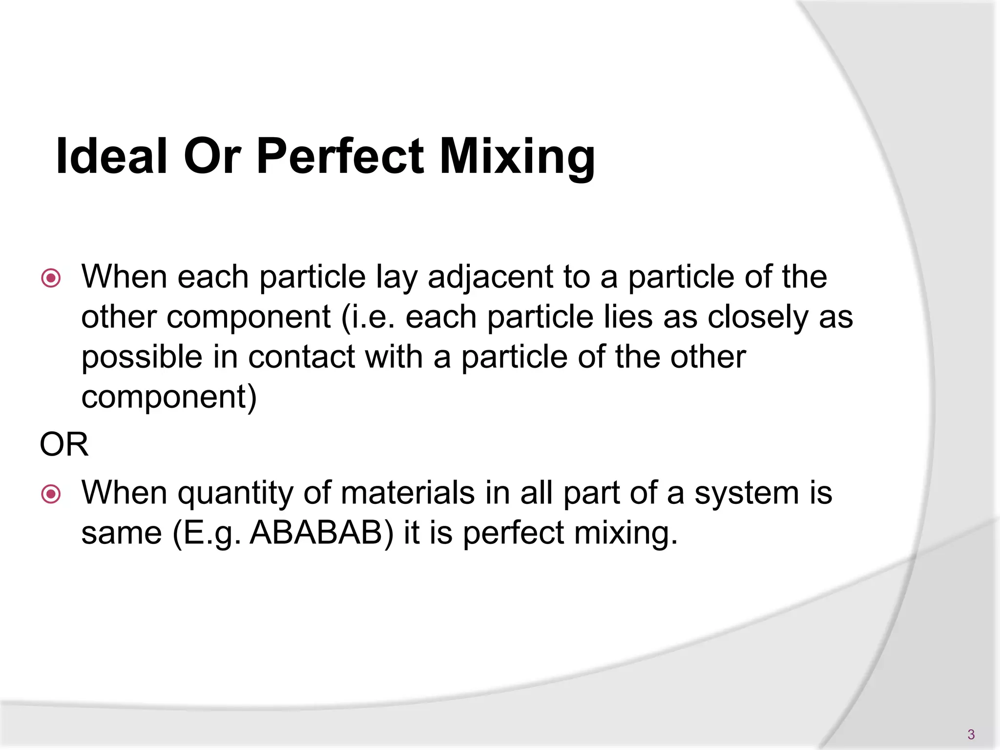
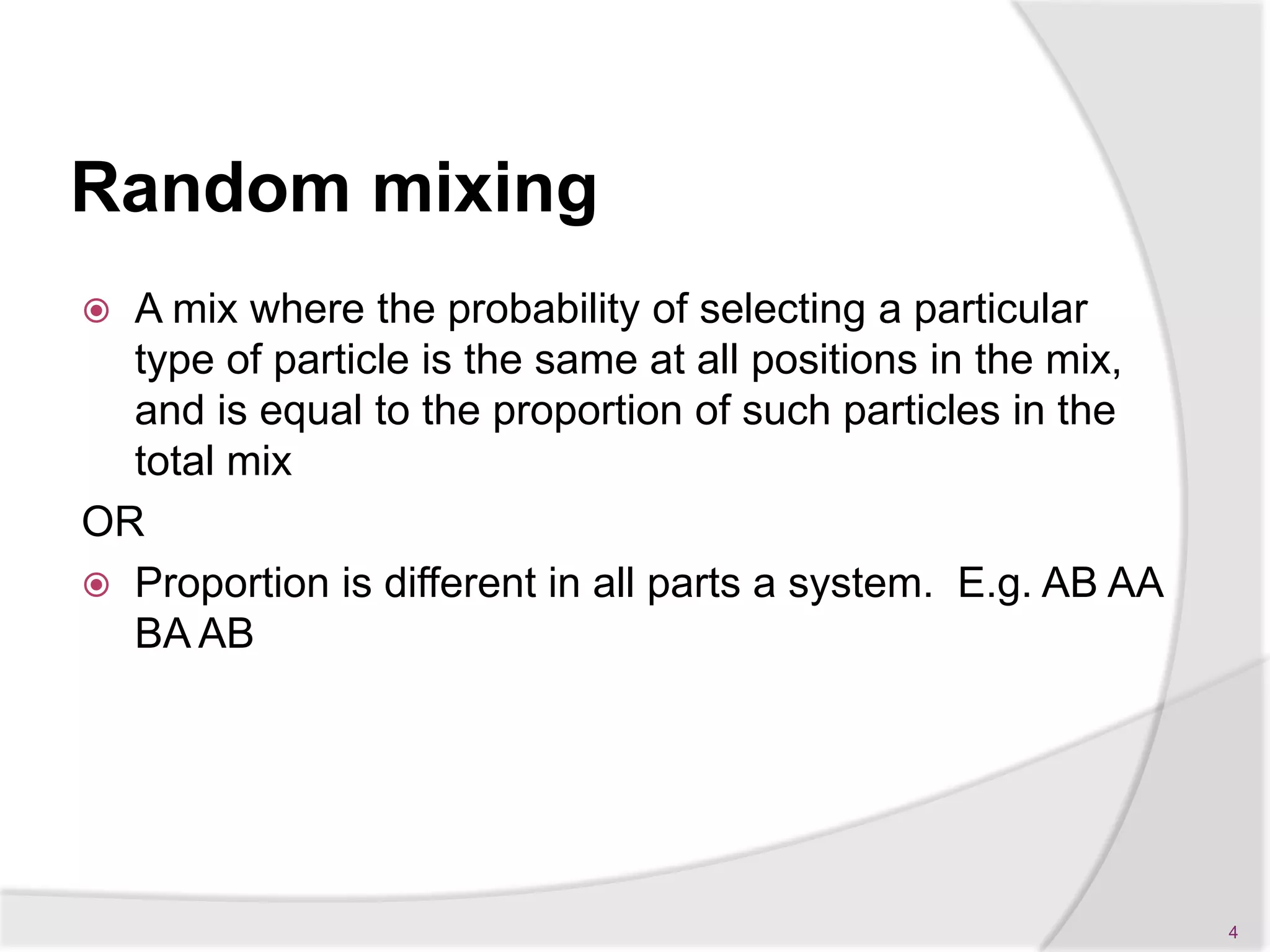

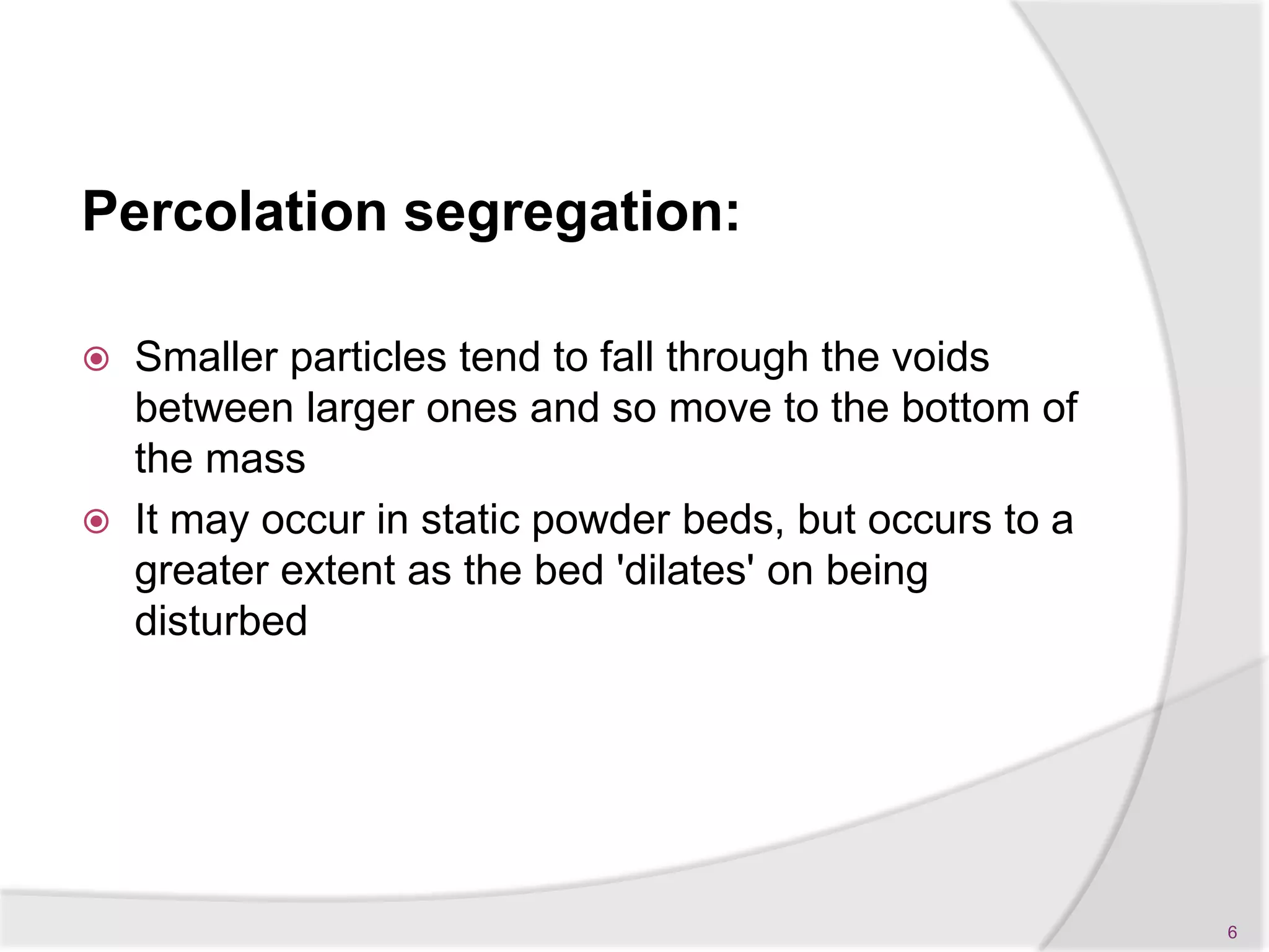
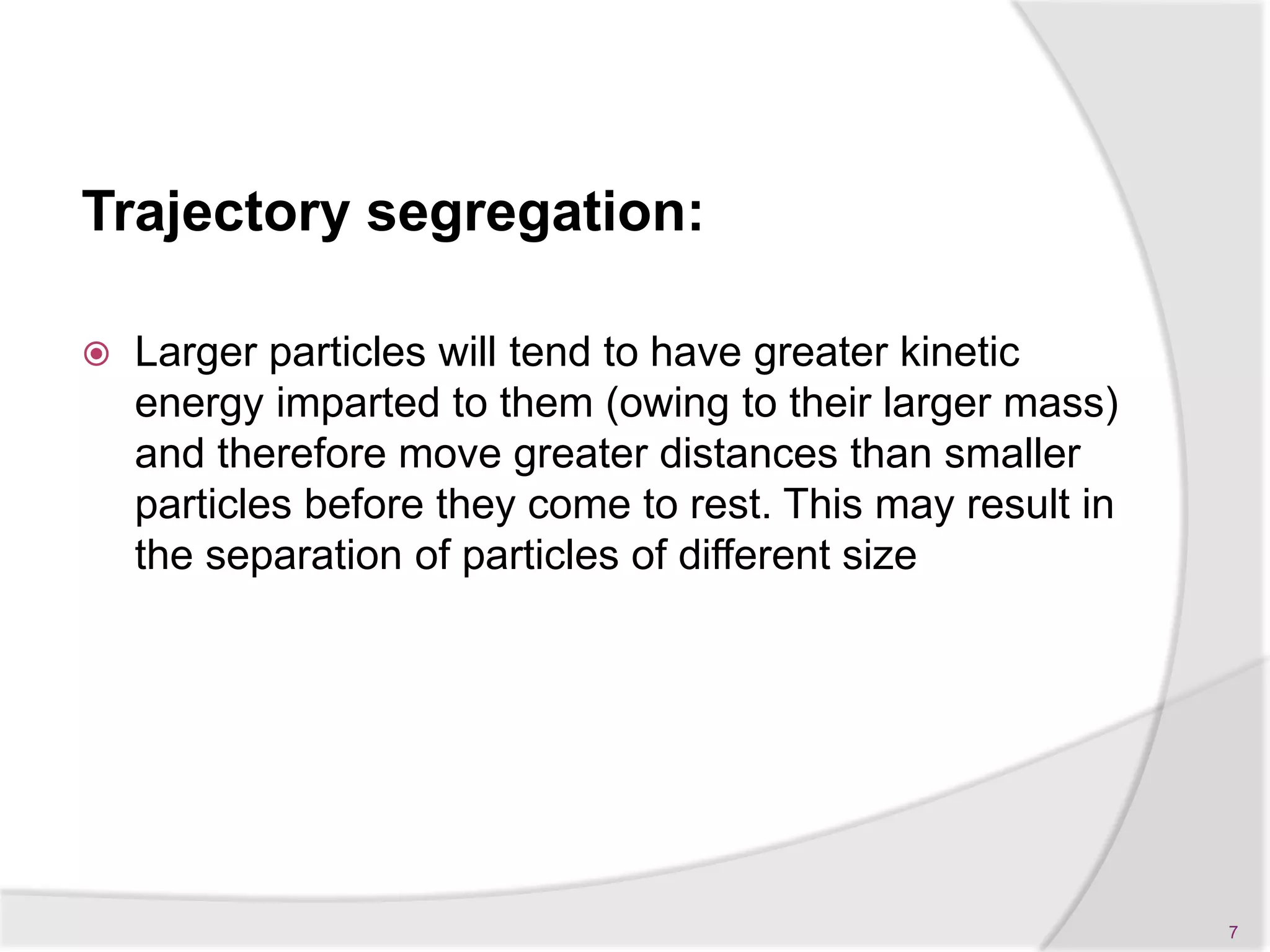


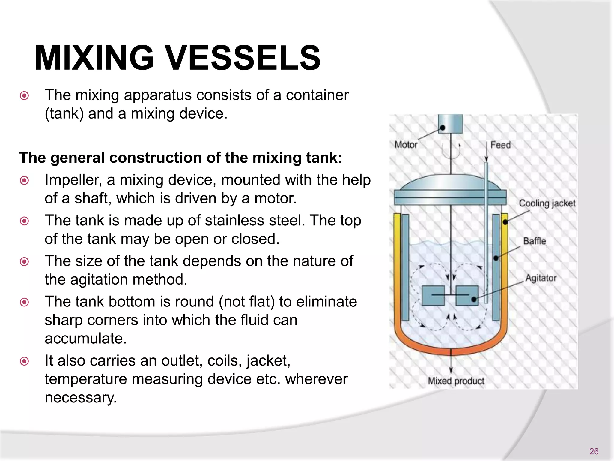


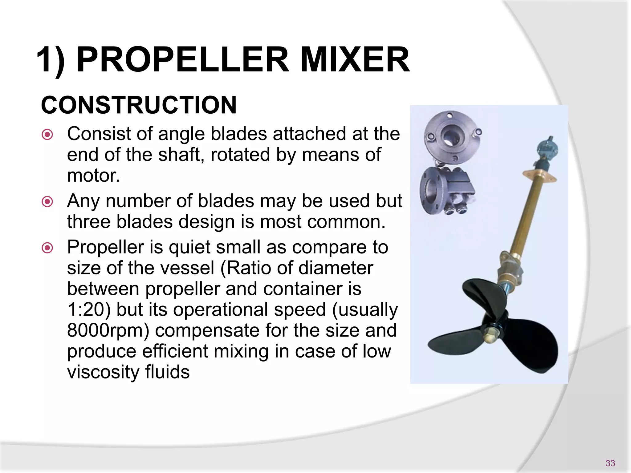


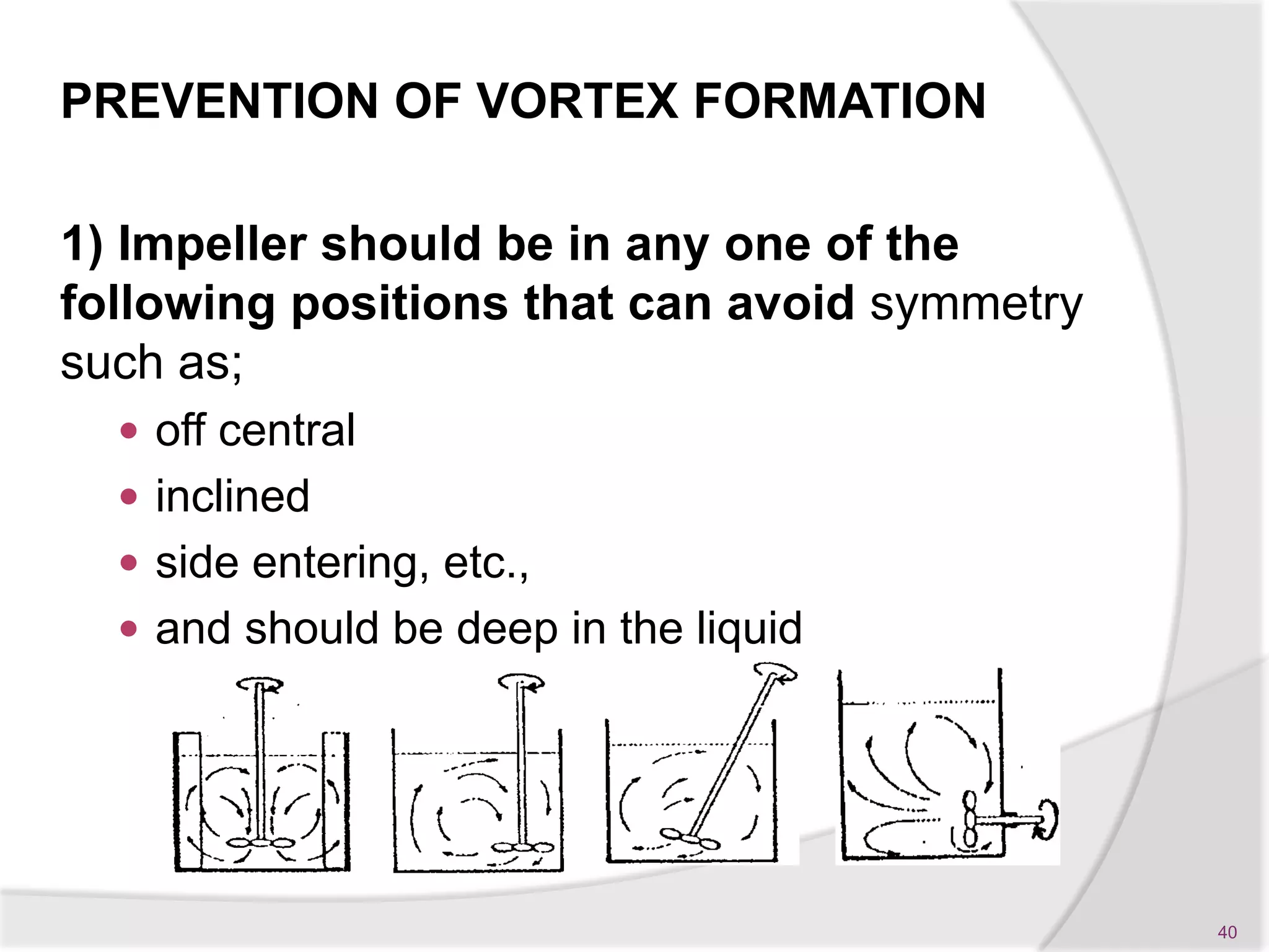

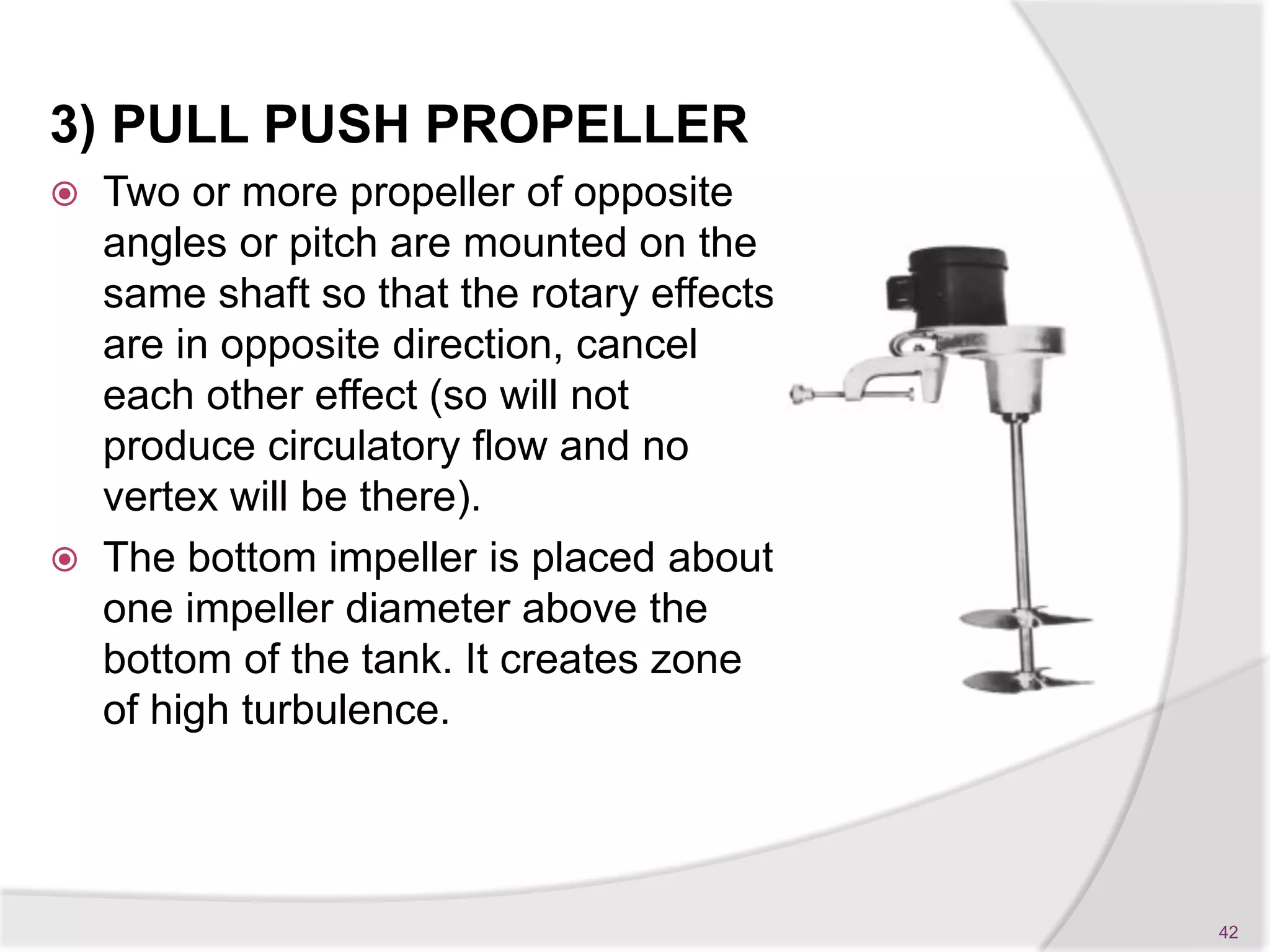
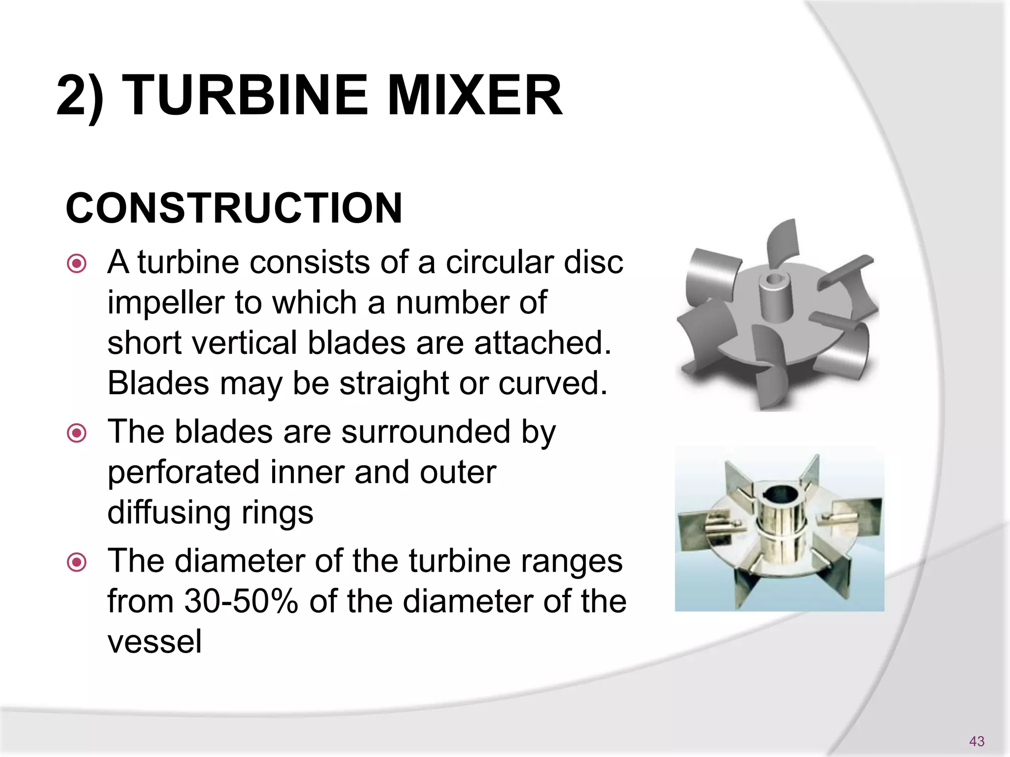


This document provides information about mixing in pharmaceutical processes. It defines mixing as a process that combines two or more components so that each particle is in contact with particles of the other ingredients. Ideal mixing occurs when the quantity of materials is the same in all parts of the system. The objectives, types, mechanisms, equipment, and flow patterns involved in liquid and powder mixing are described in detail. Different types of impellers like propellers, turbines, and paddles used for mixing are also explained.


![[Power Point] Mixing - Pharmaceutical Engineering](https://cdn.slidesharecdn.com/ss_thumbnails/forslideshare-151107043333-lva1-app6892-thumbnail.jpg?width=640&height=640&fit=bounds)


![[Paperwork] Mixing - Pharmaceutical Engineering](https://cdn.slidesharecdn.com/ss_thumbnails/papermixingcomplete-151107042824-lva1-app6892-thumbnail.jpg?width=640&height=640&fit=bounds)


