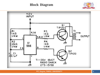
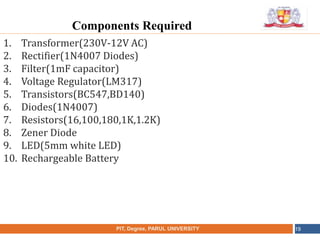
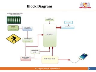
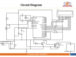
•
NAME OF THE INSTITUTE, PARUL UNIVERSITYPIT, Degree , PARUL UNIVERSITY 1
Minor Project
Presented by
Mr. DEBASIS KUMAR PATEL
Parul Institute of Technology, LIMDA
•
NAME OF THE INSTITUTE, PARUL UNIVERSITYPIT, Degree, PARUL UNIVERSITY 2
1. Project-1
Ultra Simple Inverter Circuit
2. Project-2
The Automatic LED Emergency Light
3. Project-3
Foot Step Power Generation System
Minor Project List
•
NAME OF THE INSTITUTE, PARUL UNIVERSITYPIT, Degree, PARUL UNIVERSITY 3
1. 556 IC Timer Circuit
2. 1k ohm register
3. Two transistor
4. 1-Transformer (12-0- 12/3AMP)
5. 12-Volt DC Battery.
Component Required
•
NAME OF THE INSTITUTE, PARUL UNIVERSITYPIT, Degree, PARUL UNIVERSITY 4
Contents:-
1. Component Required
2. Block Diagram
3. Application
4. Execution
Project-1:
Ultra Simple Inverter Circuit
•
NAME OF THE INSTITUTE, PARUL UNIVERSITYPIT, Degree, PARUL UNIVERSITY 5
Block Diagram
•
NAME OF THE INSTITUTE, PARUL UNIVERSITYPIT, Degree , PARUL UNIVERSITY 6
1. This circuit is low power inverter circuit and consist of 9
component.
2. The output is available at IC 556 pin 5. The second section is
wired as a phase inverter. That output is available at IC 556 pin
9.
3. Voltage input is 10-16v dc into 50 HZ.
4. And then voltage will be raised to about 230 V with power 25-
30 W. The first section of IC 556 timer chip is wire as an a
stable oscillator with R2 and C1 setting the frequency.
5. The transformer use 230 V / 12 VCT unit that is connected
backwards, so that it steps the voltage up rather than down. At
resistor R3 and R4 keep output transistor Q1 and Q2 from
loading the transistor. The transistor drive the transformer.
4.Working Principle
•
NAME OF THE INSTITUTE, PARUL UNIVERSITYPIT, Degree, PARUL UNIVERSITY 7
Advantages
Advantage:
1. Cheaper in cost.
2. Easily made by own
•
NAME OF THE INSTITUTE, PARUL UNIVERSITYPIT, Degree, PARUL UNIVERSITY 8
Application
1. Domestic-Based Inverter
(The circuit can we use to supply lamp or other
electronic devices)
•
NAME OF THE INSTITUTE, PARUL UNIVERSITYPIT, Degree, PARUL UNIVERSITY 9
Execution:
1. Reading the literature or books for the topic
2. Understanding the applications
3. Circuit Diagram
4. Buying components
5. Prepare model
Outcome:
To convert 12v DC into 230v AC.
Execution
•
NAME OF THE INSTITUTE, PARUL UNIVERSITYPIT, Degree, PARUL UNIVERSITY 10
Project-2:
The Automatic LED Emergency Light
Objective: To make the “Automatic LED Emergency Light”.
ABSTRACT:
Now days, we have frequent interruption in the main Power
Supply. So here we make a LED Light, which will provides very
bright light which turns on when the mains supply is not there.
•
NAME OF THE INSTITUTE, PARUL UNIVERSITYPIT, Degree , PARUL UNIVERSITY 11
Components Required
1. Transformer(230V-12V AC)
2. Rectifier(1N4007 Diodes)
3. Filter(1mF capacitor)
4. Voltage Regulator(LM317)
5. Transistors(BC547,BD140)
6. Diodes(1N4007)
7. Resistors(16,100,180,1K,1.2K)
8. Zener Diode
9. LED(5mm white LED)
10. Rechargeable Battery
•
NAME OF THE INSTITUTE, PARUL UNIVERSITYPIT, Degree, PARUL UNIVERSITY 12
Block Diagram
•
NAME OF THE INSTITUTE, PARUL UNIVERSITYPIT, Degree, PARUL UNIVERSITY 13
Circuit Diagram
•
NAME OF THE INSTITUTE, PARUL UNIVERSITYPIT, Degree, PARUL UNIVERSITY 14
Working Principle
The charger power supply section
It is built around 3-terminal adjustable regulator IC LM317
(IC1). In the charger power supply section, input AC mains is
stepped down by transformer X1 to deliver 9V, 500 mA to the
bridge rectifier, which comprises diodes D1 through D4. Filter
capacitor C1 eliminates ripples.
 Unregulated DC voltage is fed to input pin 3 of IC1 and
provides charging current through diode D5 and limiting
resistor R16. By adjusting preset VR1, the output voltage can be
adjusted to deliver the required charging current.
 When the battery gets charged to 6.8V, zener diode ZD1
conducts and charging current from regulator IC1 finds a path
through transistor T1 to ground and it stops charging of the
battery.
•
NAME OF THE INSTITUTE, PARUL UNIVERSITYPIT, Degree , PARUL UNIVERSITY 15
Saves fuel.
 Pollution free.
 Easy to use.
 Very low cost
 Easy to install anywhere
 ON/OFF time is quick
Advantages
•
NAME OF THE INSTITUTE, PARUL UNIVERSITYPIT, Degree, PARUL UNIVERSITY 16
For Domestic use only
(for shorter time period only)
Uses at conference room, exhibition hall lighting
Uses at Direction arrow board for bathroom
Application
•
NAME OF THE INSTITUTE, PARUL UNIVERSITYPIT, Degree, PARUL UNIVERSITY 17
Execution:
1. Reading the literature or books for the topic
2. Understanding the applications
3. Circuit Diagram
4. Buying components
5. Prepare model
Outcome:
1. To provide emergency lighting at the time
2. Of power failure.
Execution
Objectives: Design of the Foot step Power Generation.
ABSTRACT:
Now days, we have not adequate amount of the fuel for the
generation of the electricity in conventional method (i.e.
Thermal Power Plant, Hydro power plant and nuclear
power plant.
So here we are going to design the Footstep Power
Generation by without using the conventional fuels.
NAME OF THE INSTITUTE, PARUL UNIVERSITYPIT, Degree, PARUL UNIVERSITY 18
Project-3:
Footstep Power Generation System
•
NAME OF THE INSTITUTE, PARUL UNIVERSITYPIT, Degree, PARUL UNIVERSITY 19
Components Required
1. Transformer(230V-12V AC)
2. Rectifier(1N4007 Diodes)
3. Filter(1mF capacitor)
4. Voltage Regulator(LM317)
5. Transistors(BC547,BD140)
6. Diodes(1N4007)
7. Resistors(16,100,180,1K,1.2K)
8. Zener Diode
9. LED(5mm white LED)
10. Rechargeable Battery
•
NAME OF THE INSTITUTE, PARUL UNIVERSITYPIT, Degree, PARUL UNIVERSITY 20
Block Diagram
•
NAME OF THE INSTITUTE, PARUL UNIVERSITYPIT, Degree, PARUL UNIVERSITY 21
Circuit Diagram
•
NAME OF THE INSTITUTE, PARUL UNIVERSITYPIT, Degree, PARUL UNIVERSITY 22
Working
When ever pressure is applied on piezoelectric
sensor
That pressure is converted into Electrical energy
 That minute voltage which is stored in the Lead Acid battery.
 That voltage is used to drive DC loads.
 Here we are using PIC16F778 to display the amount of battery get
charged.
•
NAME OF THE INSTITUTE, PARUL UNIVERSITYPIT, Degree, PARUL UNIVERSITY 23
PIEZO SENSER
PROTECTION SHEET
C1
100 pF
R1
100 k
D1
DIODE
BAT1
9 V
To adc1
vdd
Sensor Interface Circuit
•
NAME OF THE INSTITUTE, PARUL UNIVERSITYPIT, Degree, PARUL UNIVERSITY 24
Application
1. At Railway Station, Bus station, other crowded areas for lighting.
•
NAME OF THE INSTITUTE, PARUL UNIVERSITYPIT, Degree, PARUL UNIVERSITY 25
Execution:
1. Reading the literature or books for the topic
2. Understanding the applications
3. Circuit Diagram
4. Buying components
5. Prepare model
Outcome:
1. To control any LED light as per requirement
Execution

Minor project ppt by Debasis kumar patel

  • 1.
    • NAME OF THEINSTITUTE, PARUL UNIVERSITYPIT, Degree , PARUL UNIVERSITY 1 Minor Project Presented by Mr. DEBASIS KUMAR PATEL Parul Institute of Technology, LIMDA
  • 2.
    • NAME OF THEINSTITUTE, PARUL UNIVERSITYPIT, Degree, PARUL UNIVERSITY 2 1. Project-1 Ultra Simple Inverter Circuit 2. Project-2 The Automatic LED Emergency Light 3. Project-3 Foot Step Power Generation System Minor Project List
  • 3.
    • NAME OF THEINSTITUTE, PARUL UNIVERSITYPIT, Degree, PARUL UNIVERSITY 3 1. 556 IC Timer Circuit 2. 1k ohm register 3. Two transistor 4. 1-Transformer (12-0- 12/3AMP) 5. 12-Volt DC Battery. Component Required
  • 4.
    • NAME OF THEINSTITUTE, PARUL UNIVERSITYPIT, Degree, PARUL UNIVERSITY 4 Contents:- 1. Component Required 2. Block Diagram 3. Application 4. Execution Project-1: Ultra Simple Inverter Circuit
  • 5.
    • NAME OF THEINSTITUTE, PARUL UNIVERSITYPIT, Degree, PARUL UNIVERSITY 5 Block Diagram
  • 6.
    • NAME OF THEINSTITUTE, PARUL UNIVERSITYPIT, Degree , PARUL UNIVERSITY 6 1. This circuit is low power inverter circuit and consist of 9 component. 2. The output is available at IC 556 pin 5. The second section is wired as a phase inverter. That output is available at IC 556 pin 9. 3. Voltage input is 10-16v dc into 50 HZ. 4. And then voltage will be raised to about 230 V with power 25- 30 W. The first section of IC 556 timer chip is wire as an a stable oscillator with R2 and C1 setting the frequency. 5. The transformer use 230 V / 12 VCT unit that is connected backwards, so that it steps the voltage up rather than down. At resistor R3 and R4 keep output transistor Q1 and Q2 from loading the transistor. The transistor drive the transformer. 4.Working Principle
  • 7.
    • NAME OF THEINSTITUTE, PARUL UNIVERSITYPIT, Degree, PARUL UNIVERSITY 7 Advantages Advantage: 1. Cheaper in cost. 2. Easily made by own
  • 8.
    • NAME OF THEINSTITUTE, PARUL UNIVERSITYPIT, Degree, PARUL UNIVERSITY 8 Application 1. Domestic-Based Inverter (The circuit can we use to supply lamp or other electronic devices)
  • 9.
    • NAME OF THEINSTITUTE, PARUL UNIVERSITYPIT, Degree, PARUL UNIVERSITY 9 Execution: 1. Reading the literature or books for the topic 2. Understanding the applications 3. Circuit Diagram 4. Buying components 5. Prepare model Outcome: To convert 12v DC into 230v AC. Execution
  • 10.
    • NAME OF THEINSTITUTE, PARUL UNIVERSITYPIT, Degree, PARUL UNIVERSITY 10 Project-2: The Automatic LED Emergency Light Objective: To make the “Automatic LED Emergency Light”. ABSTRACT: Now days, we have frequent interruption in the main Power Supply. So here we make a LED Light, which will provides very bright light which turns on when the mains supply is not there.
  • 11.
    • NAME OF THEINSTITUTE, PARUL UNIVERSITYPIT, Degree , PARUL UNIVERSITY 11 Components Required 1. Transformer(230V-12V AC) 2. Rectifier(1N4007 Diodes) 3. Filter(1mF capacitor) 4. Voltage Regulator(LM317) 5. Transistors(BC547,BD140) 6. Diodes(1N4007) 7. Resistors(16,100,180,1K,1.2K) 8. Zener Diode 9. LED(5mm white LED) 10. Rechargeable Battery
  • 12.
    • NAME OF THEINSTITUTE, PARUL UNIVERSITYPIT, Degree, PARUL UNIVERSITY 12 Block Diagram
  • 13.
    • NAME OF THEINSTITUTE, PARUL UNIVERSITYPIT, Degree, PARUL UNIVERSITY 13 Circuit Diagram
  • 14.
    • NAME OF THEINSTITUTE, PARUL UNIVERSITYPIT, Degree, PARUL UNIVERSITY 14 Working Principle The charger power supply section It is built around 3-terminal adjustable regulator IC LM317 (IC1). In the charger power supply section, input AC mains is stepped down by transformer X1 to deliver 9V, 500 mA to the bridge rectifier, which comprises diodes D1 through D4. Filter capacitor C1 eliminates ripples.  Unregulated DC voltage is fed to input pin 3 of IC1 and provides charging current through diode D5 and limiting resistor R16. By adjusting preset VR1, the output voltage can be adjusted to deliver the required charging current.  When the battery gets charged to 6.8V, zener diode ZD1 conducts and charging current from regulator IC1 finds a path through transistor T1 to ground and it stops charging of the battery.
  • 15.
    • NAME OF THEINSTITUTE, PARUL UNIVERSITYPIT, Degree , PARUL UNIVERSITY 15 Saves fuel.  Pollution free.  Easy to use.  Very low cost  Easy to install anywhere  ON/OFF time is quick Advantages
  • 16.
    • NAME OF THEINSTITUTE, PARUL UNIVERSITYPIT, Degree, PARUL UNIVERSITY 16 For Domestic use only (for shorter time period only) Uses at conference room, exhibition hall lighting Uses at Direction arrow board for bathroom Application
  • 17.
    • NAME OF THEINSTITUTE, PARUL UNIVERSITYPIT, Degree, PARUL UNIVERSITY 17 Execution: 1. Reading the literature or books for the topic 2. Understanding the applications 3. Circuit Diagram 4. Buying components 5. Prepare model Outcome: 1. To provide emergency lighting at the time 2. Of power failure. Execution
  • 18.
    Objectives: Design ofthe Foot step Power Generation. ABSTRACT: Now days, we have not adequate amount of the fuel for the generation of the electricity in conventional method (i.e. Thermal Power Plant, Hydro power plant and nuclear power plant. So here we are going to design the Footstep Power Generation by without using the conventional fuels. NAME OF THE INSTITUTE, PARUL UNIVERSITYPIT, Degree, PARUL UNIVERSITY 18 Project-3: Footstep Power Generation System
  • 19.
    • NAME OF THEINSTITUTE, PARUL UNIVERSITYPIT, Degree, PARUL UNIVERSITY 19 Components Required 1. Transformer(230V-12V AC) 2. Rectifier(1N4007 Diodes) 3. Filter(1mF capacitor) 4. Voltage Regulator(LM317) 5. Transistors(BC547,BD140) 6. Diodes(1N4007) 7. Resistors(16,100,180,1K,1.2K) 8. Zener Diode 9. LED(5mm white LED) 10. Rechargeable Battery
  • 20.
    • NAME OF THEINSTITUTE, PARUL UNIVERSITYPIT, Degree, PARUL UNIVERSITY 20 Block Diagram
  • 21.
    • NAME OF THEINSTITUTE, PARUL UNIVERSITYPIT, Degree, PARUL UNIVERSITY 21 Circuit Diagram
  • 22.
    • NAME OF THEINSTITUTE, PARUL UNIVERSITYPIT, Degree, PARUL UNIVERSITY 22 Working When ever pressure is applied on piezoelectric sensor That pressure is converted into Electrical energy  That minute voltage which is stored in the Lead Acid battery.  That voltage is used to drive DC loads.  Here we are using PIC16F778 to display the amount of battery get charged.
  • 23.
    • NAME OF THEINSTITUTE, PARUL UNIVERSITYPIT, Degree, PARUL UNIVERSITY 23 PIEZO SENSER PROTECTION SHEET C1 100 pF R1 100 k D1 DIODE BAT1 9 V To adc1 vdd Sensor Interface Circuit
  • 24.
    • NAME OF THEINSTITUTE, PARUL UNIVERSITYPIT, Degree, PARUL UNIVERSITY 24 Application 1. At Railway Station, Bus station, other crowded areas for lighting.
  • 25.
    • NAME OF THEINSTITUTE, PARUL UNIVERSITYPIT, Degree, PARUL UNIVERSITY 25 Execution: 1. Reading the literature or books for the topic 2. Understanding the applications 3. Circuit Diagram 4. Buying components 5. Prepare model Outcome: 1. To control any LED light as per requirement Execution