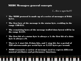
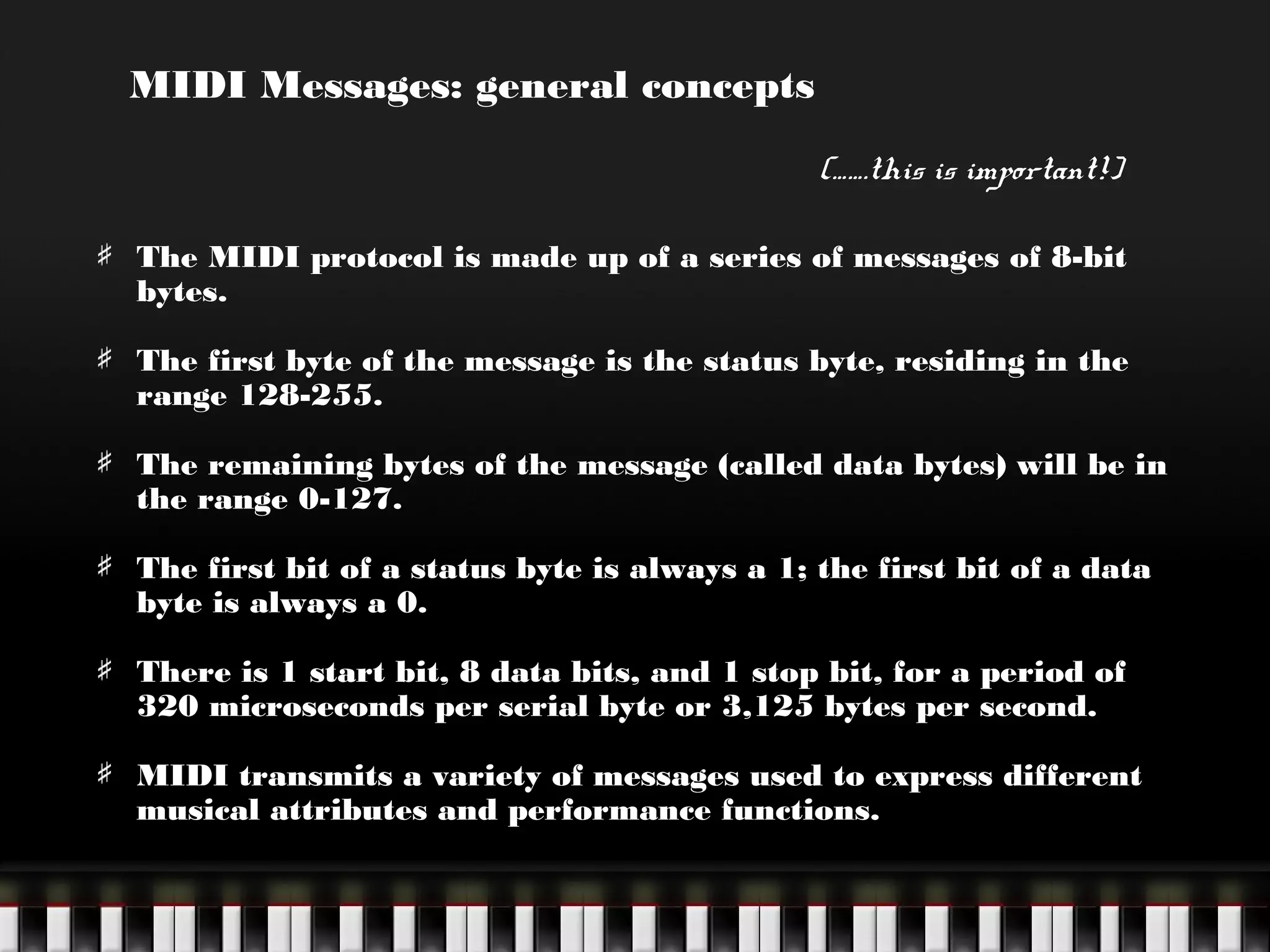
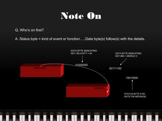
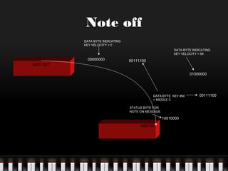
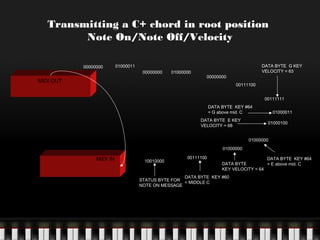
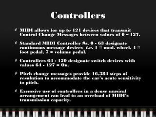
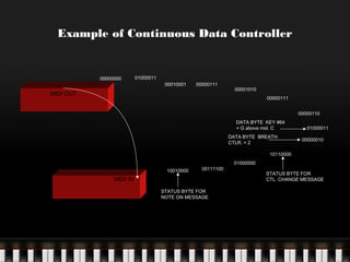
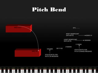
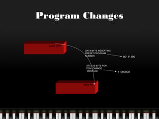
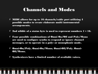
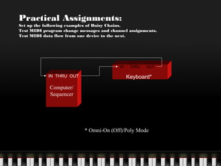
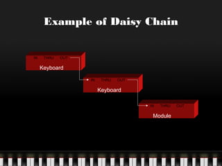
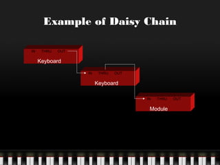
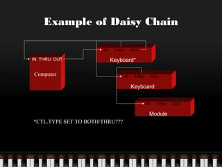
MIDI Messages: general concepts
(…….this is important!)
The MIDI protocol is made up of a series of messages of 8-bit
bytes.
The first byte of the message is the status byte, residing in the
range 128-255.
The remaining bytes of the message (called data bytes) will be in
the range 0-127.
The first bit of a status byte is always a 1; the first bit of a data
byte is always a 0.
There is 1 start bit, 8 data bits, and 1 stop bit, for a period of
320 microseconds per serial byte or 3,125 bytes per second.
MIDI transmits a variety of messages used to express different
musical attributes and performance functions.
Note On
Q. Who’s on first?
A. Status byte = kind of event or function…..Data byte(s) follow(s) with the details.
DATA BYTE INDICATING
KEY VELOCITY = 64

MIDI OUT

01000000

DATA BYTE INDICATING
KEY #60 = MIDDLE C

00111100
10010000

MIDI IN
STATUS BYTE FOR
NOTE ON MESSAGE
Note off
DATA BYTE INDICATING
KEY VELOCITY = 0
DATA BYTE INDICATING
KEY VELOCITY = 64

00000000
MIDI OUT

00111100
01000000

DATA BYTE KEY #60
= MIDDLE C
STATUS BYTE FOR
NOTE ON MESSAGE

10010000
MIDI IN

00111100
Transmitting a C+ chord in root position
Note On/Note Off/Velocity
00000000

DATA BYTE G KEY
VELOCITY = 63

01000011
00000000

MIDI OUT

01000000

00000000
00111100

00111111
DATA BYTE KEY #64
= G above mid. C
DATA BYTE E KEY
VELOCITY = 68

01000011
01000100

01000000
01000000

MIDI IN

10010000

00111100

DATA BYTE KEY #64
DATA BYTE
= E above mid. C
KEY VELOCITY = 64

DATA BYTE KEY #60
STATUS BYTE FOR
= MIDDLE C
NOTE ON MESSAGE
Controllers
MIDI allows for up to 121 devices that transmit
Control Change Messages between values of 0 – 127.
Standard MIDI Controller #s. 0 - 63 designate
continuous message devices i.e. 1 = mod. wheel, 4 =
foot pedal, 7 = volume pedal.
Controllers 64 - 120 designate switch devices with
values 64 - 127 = On.
Pitch change messages provide 16,384 steps of
resolution to accommodate the ear’s acute sensitivity
to pitch.
Excessive use of controllers in a dense musical
arrangement can lead to an overload of MIDI’s
transmission capacity.
Example of Continuous Data Controller

00000000

01000011
00010001

00000111

MIDI OUT

00001010
00000111
00000110
DATA BYTE KEY #64
= G above mid. C
DATA BYTE BREATH
CTLR. = 2

01000011
00000010

10110000
10010000

00111100

MIDI IN
STATUS BYTE FOR
NOTE ON MESSAGE

01000000
STATUS BYTE FOR
CTL. CHANGE MESSAGE
Pitch Bend
MIDI OUT

ETC……...

MOST SIGNIFICANT
DATA BYTE
LEAST SIGNIFICANT
DATA BYTE

00000110
00000000

11100000
10010000

00111100

MIDI IN
STATUS BYTE FOR
NOTE ON MESSAGE

01000000
STATUS BYTE FOR
PITCH CHANGE MESSAGE
Program Changes
MIDI OUT
DATA BYTE INDICATING
PRESET PROGRAM
NUMBER

STATUS BYTE FOR
PGM. CHANGE
MESSAGE

MIDI IN

00111100

11000000
Channels and Modes
MIDI allows for up to 16 channels/cable port utilizing 4
possible modes to create elaborate multi instrumental
arrangements.
2nd nibble of a status byte is used to represent numbers 1 – 16.
Four possible combinations of Omni On/Off and Poly/Mono
are used to configure synths to respond or ignore channel
messages, or to operate in a poly- or monophonic mode.
Omni-On/Poly, Omni-On/Mono, Omni-Off/Poly, OmniOff/Mono.
Synthesizers have a limited number of available voices.
Practical Assignments:

Set up the following examples of Daisy Chains.
Test MIDI program change messages and channel assignments.
Test MIDI data flow from one device to the next.

IN

IN THRU OUT

THRU

OUT

Keyboard*

Computer/
Sequencer

* Omni-On (Off)/Poly Mode
Example of Daisy Chain
IN

THRU

OUT

Keyboard
IN

THRU

OUT

Keyboard
IN

THRU

Module

OUT
Example of Daisy Chain
IN

THRU

OUT

Keyboard
IN

THRU

OUT

Keyboard
IN

THRU

Module

OUT
Example of Daisy Chain
IN

IN THRU OUT

THRU

OUT

Keyboard*

Computer

IN

THRU

OUT

Keyboard
IN

THRU

Module
*CTL.TYPE SET TO BOTH/THRU???

OUT

Midi message formats

  • 1.
    MIDI Messages: generalconcepts (…….this is important!) The MIDI protocol is made up of a series of messages of 8-bit bytes. The first byte of the message is the status byte, residing in the range 128-255. The remaining bytes of the message (called data bytes) will be in the range 0-127. The first bit of a status byte is always a 1; the first bit of a data byte is always a 0. There is 1 start bit, 8 data bits, and 1 stop bit, for a period of 320 microseconds per serial byte or 3,125 bytes per second. MIDI transmits a variety of messages used to express different musical attributes and performance functions.
  • 2.
    Note On Q. Who’son first? A. Status byte = kind of event or function…..Data byte(s) follow(s) with the details. DATA BYTE INDICATING KEY VELOCITY = 64 MIDI OUT 01000000 DATA BYTE INDICATING KEY #60 = MIDDLE C 00111100 10010000 MIDI IN STATUS BYTE FOR NOTE ON MESSAGE
  • 3.
    Note off DATA BYTEINDICATING KEY VELOCITY = 0 DATA BYTE INDICATING KEY VELOCITY = 64 00000000 MIDI OUT 00111100 01000000 DATA BYTE KEY #60 = MIDDLE C STATUS BYTE FOR NOTE ON MESSAGE 10010000 MIDI IN 00111100
  • 4.
    Transmitting a C+chord in root position Note On/Note Off/Velocity 00000000 DATA BYTE G KEY VELOCITY = 63 01000011 00000000 MIDI OUT 01000000 00000000 00111100 00111111 DATA BYTE KEY #64 = G above mid. C DATA BYTE E KEY VELOCITY = 68 01000011 01000100 01000000 01000000 MIDI IN 10010000 00111100 DATA BYTE KEY #64 DATA BYTE = E above mid. C KEY VELOCITY = 64 DATA BYTE KEY #60 STATUS BYTE FOR = MIDDLE C NOTE ON MESSAGE
  • 5.
    Controllers MIDI allows forup to 121 devices that transmit Control Change Messages between values of 0 – 127. Standard MIDI Controller #s. 0 - 63 designate continuous message devices i.e. 1 = mod. wheel, 4 = foot pedal, 7 = volume pedal. Controllers 64 - 120 designate switch devices with values 64 - 127 = On. Pitch change messages provide 16,384 steps of resolution to accommodate the ear’s acute sensitivity to pitch. Excessive use of controllers in a dense musical arrangement can lead to an overload of MIDI’s transmission capacity.
  • 6.
    Example of ContinuousData Controller 00000000 01000011 00010001 00000111 MIDI OUT 00001010 00000111 00000110 DATA BYTE KEY #64 = G above mid. C DATA BYTE BREATH CTLR. = 2 01000011 00000010 10110000 10010000 00111100 MIDI IN STATUS BYTE FOR NOTE ON MESSAGE 01000000 STATUS BYTE FOR CTL. CHANGE MESSAGE
  • 7.
    Pitch Bend MIDI OUT ETC……... MOSTSIGNIFICANT DATA BYTE LEAST SIGNIFICANT DATA BYTE 00000110 00000000 11100000 10010000 00111100 MIDI IN STATUS BYTE FOR NOTE ON MESSAGE 01000000 STATUS BYTE FOR PITCH CHANGE MESSAGE
  • 8.
    Program Changes MIDI OUT DATABYTE INDICATING PRESET PROGRAM NUMBER STATUS BYTE FOR PGM. CHANGE MESSAGE MIDI IN 00111100 11000000
  • 9.
    Channels and Modes MIDIallows for up to 16 channels/cable port utilizing 4 possible modes to create elaborate multi instrumental arrangements. 2nd nibble of a status byte is used to represent numbers 1 – 16. Four possible combinations of Omni On/Off and Poly/Mono are used to configure synths to respond or ignore channel messages, or to operate in a poly- or monophonic mode. Omni-On/Poly, Omni-On/Mono, Omni-Off/Poly, OmniOff/Mono. Synthesizers have a limited number of available voices.
  • 10.
    Practical Assignments: Set upthe following examples of Daisy Chains. Test MIDI program change messages and channel assignments. Test MIDI data flow from one device to the next. IN IN THRU OUT THRU OUT Keyboard* Computer/ Sequencer * Omni-On (Off)/Poly Mode
  • 11.
    Example of DaisyChain IN THRU OUT Keyboard IN THRU OUT Keyboard IN THRU Module OUT
  • 12.
    Example of DaisyChain IN THRU OUT Keyboard IN THRU OUT Keyboard IN THRU Module OUT
  • 13.
    Example of DaisyChain IN IN THRU OUT THRU OUT Keyboard* Computer IN THRU OUT Keyboard IN THRU Module *CTL.TYPE SET TO BOTH/THRU??? OUT