Download to read offline

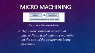
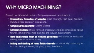

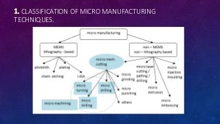
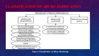
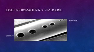
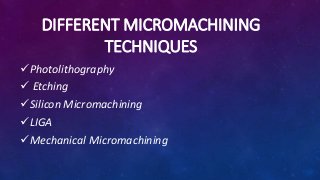

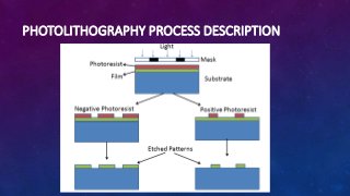


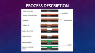

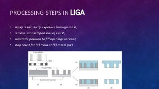
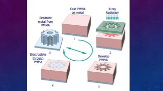


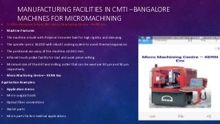
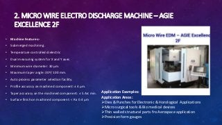


The document presents an overview of micromachining, a technology for fabricating micro-components sized between 1 to 500 μm, essential for high-precision manufacturing in modern industries. It discusses various micromachining techniques including photolithography, etching, and the LIGA process, highlighting their applications in creating complex microstructures and components. It also details the features and applications of advanced micromachining machines available, emphasizing their significance in fields such as biomedical devices and aerospace.


