SlideShare a Scribd company logo
1 of 44
Download to read offline
140
© 2017 Pearson Education, Inc., Hoboken, NJ. All rights reserved. This material is protected under all copyright laws as they currently exist.
No portion of this material may be reproduced, in any form or by any means, without permission in writing from the publisher.
0
1.50
4.60
8.00
11.00
11.80
11.80
12.00
16.60
20.00
21.50
19.50
18.50
0
0.0005
0.0015
0.0025
0.0035
0.0050
0.0080
0.0200
0.0400
0.1000
0.2800
0.4000
0.4600
Load (kip) Elongation (in.)
Solution
A =
1
4
p(0.503)2
= 0.1987 in2
L = 2.00 in.
s(ksi)	 P(in.>in.)
	 0	 0
	 7.55	 0.00025
	23.15	 0.00075
	40.26	 0.00125
	55.36	 0.00175
	 59.38	 0.0025
	 59.38	 0.0040
	 60.39	 0.010
	 83.54	 0.020
100.65	 0.050
108.20	 0.140
98.13	 0.200
93.10	 0.230
Eapprox =
48
0.0015
= 32.0(103
) ksi Ans.
3–1.
A tension test was performed on a steel specimen having an
original diameter of 0.503 in. and gage length of 2.00 in.The
data is listed in the table. Plot the stress–strain diagram and
determine approximately the modulus of elasticity, the yield
stress, the ultimate stress, and the fracture stress. Use a scale
of 1 in. = 20 ksi and 1 in. = 0.05 in.in. Redraw the elastic
region, using the same stress scale but a strain scale of
1 in. = 0.001 in.in.
Ans:
(su)approx = 110 ksi, (sf)approx = 93.1 ksi,
(sY)approx = 55 ksi, Eapprox = 32.0(103
) ksi
This
w
ork
is
protected
by
U
nited
States
copyrightlaw
s
and
is
provided
solely
forthe
use
ofinstructors
in
teaching
theircourses
and
assessing
studentlearning.D
issem
ination
orsale
ofany
partofthis
w
ork
(including
on
the
W
orld
W
ide
W
eb)
w
illdestroy
the
integrity
ofthe
w
ork
and
is
notperm
itted.
Mechanics of Materials in SI Units Global Edition 10th Edition Hibbeler Solutions Manual
Full Download: https://alibabadownload.com/product/mechanics-of-materials-in-si-units-global-edition-10th-edition-hibbeler-solut
This sample only, Download all chapters at: AlibabaDownload.com
141
© 2017 Pearson Education, Inc., Hoboken, NJ. All rights reserved. This material is protected under all copyright laws as they currently exist.
No portion of this material may be reproduced, in any form or by any means, without permission in writing from the publisher.
3–2.
Data taken from a stress–strain test for a ceramic are given
in the table. The curve is linear between the origin and the
first point. Plot the diagram, and determine the modulus of
elasticity and the modulus of resilience.
Solution
Modulus of Elasticity: From the stress–strain diagram
	 E =
33.2 - 0
0.0006 - 0
= 55.31103
2 ksi Ans.
Modulus of Resilience: The modulus of resilience is equal to the area under the
linear portion of the stress–strain diagram (shown shaded).
	 ur =
1
2
(33.2)1103
2 ¢
lb
in2
≤¢0.0006
in.
in.
≤ = 9.96
in # lb
in3
 Ans.
Ans:
E = 55.31103
2 ksi, ur = 9.96
in # lb
in3
0
33.2
45.5
49.4
51.5
53.4
0
0.0006
0.0010
0.0014
0.0018
0.0022
S (ksi) P (in./in.)
This
w
ork
is
protected
by
U
nited
States
copyrightlaw
s
and
is
provided
solely
forthe
use
ofinstructors
in
teaching
theircourses
and
assessing
studentlearning.D
issem
ination
orsale
ofany
partofthis
w
ork
(including
on
the
W
orld
W
ide
W
eb)
w
illdestroy
the
integrity
ofthe
w
ork
and
is
notperm
itted.
142
© 2017 Pearson Education, Inc., Hoboken, NJ. All rights reserved. This material is protected under all copyright laws as they currently exist.
No portion of this material may be reproduced, in any form or by any means, without permission in writing from the publisher.
3–3.
Data taken from a stress–strain test for a ceramic are given
in the table. The curve is linear between the origin and the
first point. Plot the diagram, and determine approximately the
modulus of toughness.The fracture stress is sf = 53.4 ksi.
Ans:
(ut)approx = 85.0
in # lb
in3
0
33.2
45.5
49.4
51.5
53.4
0
0.0006
0.0010
0.0014
0.0018
0.0022
S (ksi) P (in./in.)
Solution
Modulus of Toughness: The modulus of toughness is equal to the area under the
stress–strain diagram (shown shaded).
(ut)approx =
1
2
(33.2)1103
2 ¢
lb
in2
≤(0.0004 + 0.0010)¢
in.
in.
≤
+ 45.51103
2 ¢
lb
in2
≤(0.0012)¢
in.
in.
≤
+
1
2
(7.90)1103
2 ¢
lb
in2
≤(0.0012)¢
in.
in.
≤
+
1
2
(12.3)1103
2 ¢
lb
in2
≤(0.0004)¢
in.
in.
≤
= 85.0
in # lb
in3
	 Ans.
This
w
ork
is
protected
by
U
nited
States
copyrightlaw
s
and
is
provided
solely
forthe
use
ofinstructors
in
teaching
theircourses
and
assessing
studentlearning.D
issem
ination
orsale
ofany
partofthis
w
ork
(including
on
the
W
orld
W
ide
W
eb)
w
illdestroy
the
integrity
ofthe
w
ork
and
is
notperm
itted.
143
© 2017 Pearson Education, Inc., Hoboken, NJ. All rights reserved. This material is protected under all copyright laws as they currently exist.
No portion of this material may be reproduced, in any form or by any means, without permission in writing from the publisher.
Solution
Modulus of Elasticity: From the stress–strain diagram, s = 40 ksi
when P = 0.001 in.in.
	 Eapprox =
40 - 0
0.001 - 0
= 40.01103
2 ksi	 Ans.
Yield Load: From the stress–strain diagram, sY = 40.0 ksi.
	 PY = sYA = 40.0c a
p
4
b(0.52
)d = 7.85 kip Ans.
Ultimate Load: From the stress–strain diagram, su = 76.25 ksi.
	 Pu = suA = 76.25c a
p
4
b(0.52
)d = 15.0 kip Ans.
*3–4.
The stress–strain diagram for a steel alloy having an original
diameter of 0.5 in. and a gage length of 2 in. is given in the
figure. Determine approximately the modulus of elasticity
for the material, the load on the specimen that causes
yielding, and the ultimate load the specimen will support.
0
70
60
50
40
30
20
10
0
s (ksi)
0
0 0.280.04 0.08 0.12 0.16 0.20 0.24
0.00350.0005 0.0010.0015 0.002 0.0025 0.003
80
P (in./in.)
Ans:
Eapprox = 40.01103
) ksi,
PY = 7.85 kip,
Pu = 15.0 kip
This
w
ork
is
protected
by
U
nited
States
copyrightlaw
s
and
is
provided
solely
forthe
use
ofinstructors
in
teaching
theircourses
and
assessing
studentlearning.D
issem
ination
orsale
ofany
partofthis
w
ork
(including
on
the
W
orld
W
ide
W
eb)
w
illdestroy
the
integrity
ofthe
w
ork
and
is
notperm
itted.
144
© 2017 Pearson Education, Inc., Hoboken, NJ. All rights reserved. This material is protected under all copyright laws as they currently exist.
No portion of this material may be reproduced, in any form or by any means, without permission in writing from the publisher.
Solution
Modulus of Elasticity: From the stress–strain diagram, s = 40 ksi
when P = 0.001 in.in.
	 E =
40 - 0
0.001 - 0
= 40.01103
) ksi
Elastic Recovery:
Elastic recovery =
s
E
=
70
40.0(103
)
= 0.00175 in.in.
Thus,
	 The amount of Elastic Recovery = 0.00175(2) = 0.00350 in. Ans.
Permanent Set:
Permanent set = 0.08 - 0.00175 = 0.07825 in.in.
Thus,
Permanent elongation = 0.07825(2) = 0.1565 in. Ans.
3–5.
The stress–strain diagram for a steel alloy having an original
diameter of 0.5 in. and a gage length of 2 in. is given in the
figure. If the specimen is loaded until it is stressed to 70 ksi,
determine the approximate amount of elastic recovery and
the increase in the gage length after it is unloaded.
0
70
60
50
40
30
20
10
0
s (ksi)
0
0 0.280.04 0.08 0.12 0.16 0.20 0.24
0.00350.0005 0.0010.0015 0.002 0.0025 0.003
80
P (in./in.)
Ans:
Elastic recovery = 0.00350 in.,
Permanent elongation = 0.1565 in.
This
w
ork
is
protected
by
U
nited
States
copyrightlaw
s
and
is
provided
solely
forthe
use
ofinstructors
in
teaching
theircourses
and
assessing
studentlearning.D
issem
ination
orsale
ofany
partofthis
w
ork
(including
on
the
W
orld
W
ide
W
eb)
w
illdestroy
the
integrity
ofthe
w
ork
and
is
notperm
itted.
145
© 2017 Pearson Education, Inc., Hoboken, NJ. All rights reserved. This material is protected under all copyright laws as they currently exist.
No portion of this material may be reproduced, in any form or by any means, without permission in writing from the publisher.
Solution
Modulus of Resilience: The modulus of resilience is equal to the area
under the linear portion of the stress–strain diagram.
(ur)approx =
1
2
(40.0)(103
)a
lb
in2
b a0.001
in.
in.
b = 20.0
in # lb
in3
 Ans.
Modulus of Toughness: The modulus of toughness is equal to the total area under
the stress–strain diagram and can be approximated by counting the number of
squares. The total number of squares is 45.
(ut)approx = 45a10
kip
in2
b a0.04
in.
in.
b = 18.0
in # kip
in3
 Ans.
3–6.
The stress–strain diagram for a steel alloy having an original
diameter of 0.5 in. and a gage length of 2 in. is given in the
figure. Determine approximately the modulus of resilience
and the modulus of toughness for the material.
0
70
60
50
40
30
20
10
0
s (ksi)
0
0 0.280.04 0.08 0.12 0.16 0.20 0.24
0.00350.0005 0.0010.0015 0.002 0.0025 0.003
80
P (in./in.)
Ans:
(ur)approx = 20.0
in # lb
in3
,
(ut)approx = 18.0
in # kip
in3
This
w
ork
is
protected
by
U
nited
States
copyrightlaw
s
and
is
provided
solely
forthe
use
ofinstructors
in
teaching
theircourses
and
assessing
studentlearning.D
issem
ination
orsale
ofany
partofthis
w
ork
(including
on
the
W
orld
W
ide
W
eb)
w
illdestroy
the
integrity
ofthe
w
ork
and
is
notperm
itted.
146
© 2017 Pearson Education, Inc., Hoboken, NJ. All rights reserved. This material is protected under all copyright laws as they currently exist.
No portion of this material may be reproduced, in any form or by any means, without permission in writing from the publisher.
Solution
+ΣMC = 0;  FAB sin 30°(10) - 0.1(10)(5) = 0;
	 FAB = 1.0 kip
sAB =
FAB
AAB
=
1.0
p
4
(0.2)2
= 31.83 ksi
s = EP;  31.83 = 29(103
) PAB;  PAB = 0.0010981 in.in.
dAB = PAB LAB = 0.0010981a
120
cos 30°
b = 0.152 in. Ans.
3–7.
The rigid beam is supported by a pin at C and an A-36 steel
guy wire AB. If the wire has a diameter of 0.2 in., determine
how much it stretches when a distributed load of w = 100 lbft
acts on the beam.The material remains elastic.
30Њ
10 ft
C
A
B
w
Ans:
dAB = 0.152 in.
This
w
ork
is
protected
by
U
nited
States
copyrightlaw
s
and
is
provided
solely
forthe
use
ofinstructors
in
teaching
theircourses
and
assessing
studentlearning.D
issem
ination
orsale
ofany
partofthis
w
ork
(including
on
the
W
orld
W
ide
W
eb)
w
illdestroy
the
integrity
ofthe
w
ork
and
is
notperm
itted.
147
© 2017 Pearson Education, Inc., Hoboken, NJ. All rights reserved. This material is protected under all copyright laws as they currently exist.
No portion of this material may be reproduced, in any form or by any means, without permission in writing from the publisher.
Solution
sin u =
0.0625
10
;	 u = 0.3581°
a = 90 + 0.3581° = 90.3581°
AB =
10
cos 30°
= 11.5470 ft
AB′ = 2102
+ 5.77352
- 2(10)(5.7735) cos 90.3581°
= 11.5782 ft
PAB =
AB′ - AB
AB
=
11.5782 - 11.5470
11.5470
= 0.002703 in.in.
sAB = EPAB = 29(103
)(0.002703) = 78.38 ksi
FAB = sAB AAB = 78.38 a
p
4
b(0.2)2
= 2.462 kip
+ ΣMC = 0;  2.462 sin 30°(10) - 10w(5) = 0;
w = 0.246 kipft Ans.
*3–8.
The rigid beam is supported by a pin at C and an A-36 steel
guy wire AB. If the wire has a diameter of 0.2 in., determine
the distributed load w if the end B is displaced 0.75 in.
downward.
30Њ
10 ft
C
A
B
w
Ans:
w = 0.246 kipft
This
w
ork
is
protected
by
U
nited
States
copyrightlaw
s
and
is
provided
solely
forthe
use
ofinstructors
in
teaching
theircourses
and
assessing
studentlearning.D
issem
ination
orsale
ofany
partofthis
w
ork
(including
on
the
W
orld
W
ide
W
eb)
w
illdestroy
the
integrity
ofthe
w
ork
and
is
notperm
itted.
148
© 2017 Pearson Education, Inc., Hoboken, NJ. All rights reserved. This material is protected under all copyright laws as they currently exist.
No portion of this material may be reproduced, in any form or by any means, without permission in writing from the publisher.
Solution
s =
P
A
=
2.5
0.875
= 2.857 ksi
s = 9.5(103
)P13
2.857(103
) = 9.5(103
)P13
P = 0.0272 in.in.
d = LP = 3(12)(0.0272) = 0.979 in. Ans.
3–9.
Acetal plastic has a stress–strain diagram as shown. If a bar
of this material has a length of 3 ft and cross-sectional area
of 0.875 in2, and is subjected to an axial load of 2.5 kip,
determine its elongation.
P (in./in.)
␴ ϭ 9.5(103
)P1/3
␴ (psi)
Ans:
d = 0.979 in.
This
w
ork
is
protected
by
U
nited
States
copyrightlaw
s
and
is
provided
solely
forthe
use
ofinstructors
in
teaching
theircourses
and
assessing
studentlearning.D
issem
ination
orsale
ofany
partofthis
w
ork
(including
on
the
W
orld
W
ide
W
eb)
w
illdestroy
the
integrity
ofthe
w
ork
and
is
notperm
itted.
149
© 2017 Pearson Education, Inc., Hoboken, NJ. All rights reserved. This material is protected under all copyright laws as they currently exist.
No portion of this material may be reproduced, in any form or by any means, without permission in writing from the publisher.
3–10.
The stress–strain diagram for an aluminum alloy specimen
having an original diameter of 0.5 in. and a gage length
of  2  in. is given in the figure. Determine approximately
the modulus of elasticity for the material, the load on the
specimen that causes yielding, and the ultimate load the
specimen will support.
Solution
Modulus of Elasticity: From the stress–strain diagram, s = 50.0 ksi when
P = 0.005 in.in. Thus
	 Eapprox =
50.0 - 0
0.005 - 0
= 10.0(103
) ksi Ans.
Yield Load: From the stress–strain diagram, sy = 50.0 ksi.Thus
	 PY = syA = 50.0c
p
4
(0.52
) d = 9.82 kip Ans.
Ultimate Load: From the stress–strain diagram, su = 68.0 ksi. Thus,
	 Pu = suA = 68.0c
p
4
(0.52
) d = 13.4 kip Ans.
0
70
60
50
40
30
20
10
00
0 0.140.02 0.04 0.06 0.08 0.10 0.12
0.01750.0025 0.0050.0075 0.01 0.01250.015
P (in./in.)
s (ksi)
0.16 0.18 0.2
0.02 0.02550.025
Ans:
Eapprox = 10.0(103
) ksi,
PY = 9.82 kip,
Pu = 13.4 kip
This
w
ork
is
protected
by
U
nited
States
copyrightlaw
s
and
is
provided
solely
forthe
use
ofinstructors
in
teaching
theircourses
and
assessing
studentlearning.D
issem
ination
orsale
ofany
partofthis
w
ork
(including
on
the
W
orld
W
ide
W
eb)
w
illdestroy
the
integrity
ofthe
w
ork
and
is
notperm
itted.
150
© 2017 Pearson Education, Inc., Hoboken, NJ. All rights reserved. This material is protected under all copyright laws as they currently exist.
No portion of this material may be reproduced, in any form or by any means, without permission in writing from the publisher.
3–11.
The stress–strain diagram for an aluminum alloy specimen
having an original diameter of 0.5 in. and a gage length of 2 in.
is given in the figure. If the specimen is loaded until it is
stressed to 60 ksi, determine the approximate amount of
elastic recovery and the increase in the gage length after it
is unloaded.
Solution
Modulus of Elasticity: From the stress–strain diagram, s = 50.0 ksi when
P = 0.005 in.in. Thus
Eapprox =
50.0 - 0
0.005 - 0
= 10.0(103
) ksi
Elastic Recovery and Permanent Set: From the stress–strain diagram, s = 60 ksi
when P = 0.04 in.in. Thus
s
E
=
60
10.0(103
)
= 0.006 in.in.
Thus,
		 Elastic Recovery = (0.006)(2) = 0.012 in. Ans.
And
		 Permanent set = 0.04 - 0.006 = 0.034 in.in.
Then
		 Permanent elongation = 0.034(2) = 0.0680 in. Ans.
0
70
60
50
40
30
20
10
00
0 0.140.02 0.04 0.06 0.08 0.10 0.12
0.01750.0025 0.0050.0075 0.01 0.01250.015
P (in./in.)
s (ksi)
0.16 0.18 0.2
0.02 0.02550.025
Ans:
Elastic recovery = 0.012 in.,
Permanent elongation = 0.0680 in.
This
w
ork
is
protected
by
U
nited
States
copyrightlaw
s
and
is
provided
solely
forthe
use
ofinstructors
in
teaching
theircourses
and
assessing
studentlearning.D
issem
ination
orsale
ofany
partofthis
w
ork
(including
on
the
W
orld
W
ide
W
eb)
w
illdestroy
the
integrity
ofthe
w
ork
and
is
notperm
itted.
151
© 2017 Pearson Education, Inc., Hoboken, NJ. All rights reserved. This material is protected under all copyright laws as they currently exist.
No portion of this material may be reproduced, in any form or by any means, without permission in writing from the publisher.
*3–12.
The stress–strain diagram for an aluminum alloy specimen
having an original diameter of 0.5 in. and a gage length of
2 in. is given in the figure. Determine approximately the
modulus of resilience and the modulus of toughness for the
material.
Solution
Modulus of Resilience: The modulus of resilience is equal to the area under the
linear portion of the stress–strain diagram.
	 (ur)approx =
1
2
350.0(103
)lbin2
4(0.005 in.in.) = 125
in # lb
in3
 Ans.
Modulus of Toughness: The modulus of toughness is equal to the entire area under
the stress–strain diagram, which can be approximated by counting the number of
squares.The total number of squares is 63.
	 (ut)approx = 63(10.0 kipin2
)(0.02 in.in.) = 12.6
in # kip
in3
 Ans.
0
70
60
50
40
30
20
10
00
0 0.140.02 0.04 0.06 0.08 0.10 0.12
0.01750.0025 0.0050.0075 0.01 0.01250.015
P (in./in.)
s (ksi)
0.16 0.18 0.2
0.02 0.02550.025
Ans:
(ur)approx = 125
in # lb
in3
,
(ut)approx = 12.6
in # kip
in3
This
w
ork
is
protected
by
U
nited
States
copyrightlaw
s
and
is
provided
solely
forthe
use
ofinstructors
in
teaching
theircourses
and
assessing
studentlearning.D
issem
ination
orsale
ofany
partofthis
w
ork
(including
on
the
W
orld
W
ide
W
eb)
w
illdestroy
the
integrity
ofthe
w
ork
and
is
notperm
itted.
152
© 2017 Pearson Education, Inc., Hoboken, NJ. All rights reserved. This material is protected under all copyright laws as they currently exist.
No portion of this material may be reproduced, in any form or by any means, without permission in writing from the publisher.
Solution
Normal Stress and Strain:
s =
P
A
=
8.00
0.7
= 11.43 ksi
P =
d
L
=
0.002
5
= 0.000400 in.in.
Modulus of Elasticity:
	 E =
s
P
=
11.43
0.000400
= 28.6(103
) ksi	 Ans.
3–13. 
A bar having a length of 5 in. and cross-sectional area of
0.7 in.2
is subjected to an axial force of 8000 lb. If the bar
stretches 0.002 in., determine the modulus of elasticity of
the material.The material has linear elastic behavior.
8000 lb8000 lb
5 in.
Ans:
E = 28.6(103
) ksi
This
w
ork
is
protected
by
U
nited
States
copyrightlaw
s
and
is
provided
solely
forthe
use
ofinstructors
in
teaching
theircourses
and
assessing
studentlearning.D
issem
ination
orsale
ofany
partofthis
w
ork
(including
on
the
W
orld
W
ide
W
eb)
w
illdestroy
the
integrity
ofthe
w
ork
and
is
notperm
itted.
153
© 2017 Pearson Education, Inc., Hoboken, NJ. All rights reserved. This material is protected under all copyright laws as they currently exist.
No portion of this material may be reproduced, in any form or by any means, without permission in writing from the publisher.
Solution
Here, we are only interested in determining the force in wire BD. Referring to the
FBD in Fig. a
a+ΣMA = 0;  FBD14
5 2(3) - 600(6) = 0  FBD = 1500 lb
The normal stress developed in the wire is
sBD =
FBD
ABD
=
1500
p
4 (0.252
)
= 30.56(103
) psi = 30.56 ksi
Since sBD 6 sy = 36 ksi, Hooke’s Law can be applied to determine the strain in
the wire.
	 sBD = EPBD;  30.56 = 29.0(103
)PBD
		     PBD = 1.054(10-3
) in.in.
The unstretched length of the wire is LBD = 232
+ 42
= 5 ft = 60 in. Thus, the
wire stretches
	 dBD = PBD LBD = 1.054(10-3
)(60)
	 = 0.0632 in. 	 Ans.
3–14. 
The rigid pipe is supported by a pin at A and an A-36 steel
guy wire BD. If the wire has a diameter of 0.25 in.,determine
how much it stretches when a load of P = 600 lb acts on
the pipe.
3 ft 3 ft
C
DA
B
P4 ft
Ans:
dBD = 0.0632 in.
This
w
ork
is
protected
by
U
nited
States
copyrightlaw
s
and
is
provided
solely
forthe
use
ofinstructors
in
teaching
theircourses
and
assessing
studentlearning.D
issem
ination
orsale
ofany
partofthis
w
ork
(including
on
the
W
orld
W
ide
W
eb)
w
illdestroy
the
integrity
ofthe
w
ork
and
is
notperm
itted.
154
© 2017 Pearson Education, Inc., Hoboken, NJ. All rights reserved. This material is protected under all copyright laws as they currently exist.
No portion of this material may be reproduced, in any form or by any means, without permission in writing from the publisher.
Solution
Here, we are only interested in determining the force in wire BD. Referring to the
FBD in Fig. a
	  a+ΣMA = 0;  FBD14
5 2(3) - P(6) = 0  FBD = 2.50 P
The unstretched length for wire BD is LBD = 232
+ 42
= 5 ft = 60 in. From the
geometry shown in Fig. b, the stretched length of wire BD is
	 LBD′ = 2602
+ 0.0752
- 2(60)(0.075) cos 143.13° = 60.060017
Thus, the normal strain is
	 PBD =
LBD′ - LBD
LBD
=
60.060017 - 60
60
= 1.0003(10-3
) in.in.
Then, the normal stress can be obtain by applying Hooke’s Law.
	 sBD = EPBD = 29(103
)31.0003(10-3
)4 = 29.01 ksi
Since sBD 6 sy = 36 ksi, the result is valid.
	 sBD =
FBD
ABD
; 29.01(103
) =
2.50 P
p
4 (0.252
)
	 P = 569.57 lb = 570 lb	 Ans.
3–15. 
The rigid pipe is supported by a pin at A and an A-36 guy
wire BD. If the wire has a diameter of 0.25 in., determine
the load P if the end C is displaced 0.075 in. downward.
3 ft 3 ft
C
DA
B
P4 ft
Ans:
P = 570 lb
This
w
ork
is
protected
by
U
nited
States
copyrightlaw
s
and
is
provided
solely
forthe
use
ofinstructors
in
teaching
theircourses
and
assessing
studentlearning.D
issem
ination
orsale
ofany
partofthis
w
ork
(including
on
the
W
orld
W
ide
W
eb)
w
illdestroy
the
integrity
ofthe
w
ork
and
is
notperm
itted.
155
© 2017 Pearson Education, Inc., Hoboken, NJ. All rights reserved. This material is protected under all copyright laws as they currently exist.
No portion of this material may be reproduced, in any form or by any means, without permission in writing from the publisher.
Solution
Stress–Strain Relationship: From the stress–strain diagram with
P = 0.1 mmmm 7 0.0015 mmmm
s - 450
0.1 - 0.0015
=
600 - 450
0.3 - 0.0015
s = 499.497 MPa
Axial Force: For each head
P = sA = 499.4971(106
)(1.5)(10-6
) = 749.24 N
Thus, the tension in the bolt is
T = 6 P = 6(749.24) = 4495 N = 4.50 kN Ans.
*3–16. 
Direct tension indicators are sometimes used instead of
torque wrenches to ensure that a bolt has a prescribed
tension when used for connections. If a nut on the bolt is
tightened so that the six 3-mm high heads of
the indicator are strained 0.1 mmmm, and leave a
contact area on each head of 1.5 mm2, determine the tension
in the bolt shank. The material has the stress–strain
diagram shown.
3 mm
s (MPa)
P (mm/mm)
0.30.0015
600
450
Ans:
T = 4.50 kN
This
w
ork
is
protected
by
U
nited
States
copyrightlaw
s
and
is
provided
solely
forthe
use
ofinstructors
in
teaching
theircourses
and
assessing
studentlearning.D
issem
ination
orsale
ofany
partofthis
w
ork
(including
on
the
W
orld
W
ide
W
eb)
w
illdestroy
the
integrity
ofthe
w
ork
and
is
notperm
itted.
156
© 2017 Pearson Education, Inc., Hoboken, NJ. All rights reserved. This material is protected under all copyright laws as they currently exist.
No portion of this material may be reproduced, in any form or by any means, without permission in writing from the publisher.
Solution
Support Reactions: Referring to the FBD of the beam, Fig. a,
a+ΣMC = 0; FAB cos 30°(10) - 0.2(10)(5) = 0 FAB = 1.1547 kip
Normal Stress and Strain Relation: The normal stress is
sAB =
FAB
AAB
=
1.1547
p
4
(0.22
)
= 36.76 ksi
For structural A992 steel alloy, Est = 29.0(103
) ksi.
	 s = EP; 36.76 = 29.0(103
)PAB
	 PAB = 0.001267 in.in.
Thus,
	 dAB = PABLAB = (0.001267 in.in.) (72 in.) = 0.0913 in. Ans.
3–17. 
The rigid beam is supported by a pin at C and an A992 steel
guy wire AB of length 6 ft. If the wire has
a diameter of 0.2 in., determine how much it stretches when
a distributed load of w = 200 lbft acts on the beam. The
wire remains elastic.
30Њ
10 ft
C
A
B
w
Ans:
dAB = 0.0913 in.
This
w
ork
is
protected
by
U
nited
States
copyrightlaw
s
and
is
provided
solely
forthe
use
ofinstructors
in
teaching
theircourses
and
assessing
studentlearning.D
issem
ination
orsale
ofany
partofthis
w
ork
(including
on
the
W
orld
W
ide
W
eb)
w
illdestroy
the
integrity
ofthe
w
ork
and
is
notperm
itted.
157
© 2017 Pearson Education, Inc., Hoboken, NJ. All rights reserved. This material is protected under all copyright laws as they currently exist.
No portion of this material may be reproduced, in any form or by any means, without permission in writing from the publisher.
Solution
Support Reactions: Referring to the FBD of the beam, Fig. a,
a+ ΣMC = 0; FAB cos 30°(10) - 10w(5) = 0 FAB =
1023
3
w
Normal Stress and Strain Relation: Referring to the geometry shown in Fig. b, and
applying cosine law and sine law,
	 LAC = 2102
+ 62
- 2(10)(6)cos 120° = 14 ft
	
sin f
6
=
sin 120°
14
; f = 21.7868°
	 sin u =
0.01
10
; u = 0.05730°
Thus,
LAB′ = 2142
+ 102
- 2(14)(10) cos (21.7868° + 0.05730°) = 6.008665 ft
Then
	 PAB =
LAB′ - LAB
LAB
=
6.008665 - 6
6
= 0.001444 in.in.
For structural A992 steel alloy, Est = 29.0(103
) ksi.Thus,
	 sAB = EPAB = 29(103
)(0.001444) = 41.88 ksi 6 50 ksi  (O.K!)
	 FAB = sABAAB;
1023
3
w = (41.88)c
p
4
(0.22
) d
	 w = 0.2279 kipft = 228 lbft Ans.
3–18. 
The rigid beam is supported by a pin at C and an A992 steel
guy wire AB of length 6 ft. If the wire has a diameter of
0.2 in., determine the distributed load w if the end B is
displaced 0.12 in. downward.The wire remains elastic.
30Њ
10 ft
C
A
B
w
Ans:
w = 228 lbft
This
w
ork
is
protected
by
U
nited
States
copyrightlaw
s
and
is
provided
solely
forthe
use
ofinstructors
in
teaching
theircourses
and
assessing
studentlearning.D
issem
ination
orsale
ofany
partofthis
w
ork
(including
on
the
W
orld
W
ide
W
eb)
w
illdestroy
the
integrity
ofthe
w
ork
and
is
notperm
itted.
158
© 2017 Pearson Education, Inc., Hoboken, NJ. All rights reserved. This material is protected under all copyright laws as they currently exist.
No portion of this material may be reproduced, in any form or by any means, without permission in writing from the publisher.
Solution
P = 0.45(10-6
)s + 0.36(10-12
)s3
,
dP = 10.45(10-6
) + 1.08(10-12
) s2
2ds
E =
ds
dP
`
s=0
=
1
0.45(10-6
)
= 2.22(106
) kPa = 2.22 GPa
The equation for the recovery line is s = 2.22(106
)(P - 0.003).
This line intersects the stress–strain curve at sYS = 2027 kPa = 2.03 MPa	 Ans.
3–19. 
The stress–strain diagram for a bone is shown, and can be
described by the equation P = 0.45110-6
2 s +
0.36110-12
2 s3
, where s is in kPa. Determine the yield
strength assuming a 0.3% offset.
P
P
P ϭ 0.45(10Ϫ6
)s + 0.36(10Ϫ12
)s3
P
s
Ans:
sYS = 2.03 MPa
This
w
ork
is
protected
by
U
nited
States
copyrightlaw
s
and
is
provided
solely
forthe
use
ofinstructors
in
teaching
theircourses
and
assessing
studentlearning.D
issem
ination
orsale
ofany
partofthis
w
ork
(including
on
the
W
orld
W
ide
W
eb)
w
illdestroy
the
integrity
ofthe
w
ork
and
is
notperm
itted.
159
© 2017 Pearson Education, Inc., Hoboken, NJ. All rights reserved. This material is protected under all copyright laws as they currently exist.
No portion of this material may be reproduced, in any form or by any means, without permission in writing from the publisher.
Solution
When P = 0.12
120(10-3
) = 0.45 s + 0.36(10-6
)s3
Solving for the real root:
s = 6873.52 kPa
ut =
LA
dA =
L
6873.52
0
(0.12 - P)ds
ut =
L
6873.52
0
(0.12 - 0.45(10-6
)s - 0.36(10-12
)s3
)ds
= 0.12 s - 0.225(10-6
)s2
- 0.09(10-12
)s4
͉
6873.52
0
= 613 kJm3
	 Ans.
d = PL = 0.12(200) = 24 mm 	 Ans.
*3–20. 
The stress–strain diagram for a bone is shown and can
be described by the equation P = 0.45110-6
2 s +
0.36110-12
2 s3
, where s is in kPa. Determine the modulus
of toughness and the amount of elongation of a 200-mm-long
region just before it fractures if failure occurs at
P = 0.12 mmmm.
P
P
P ϭ 0.45(10Ϫ6
)s + 0.36(10Ϫ12
)s3
P
s
Ans:
ut = 613 kJm3
,
d = 24 mm
This
w
ork
is
protected
by
U
nited
States
copyrightlaw
s
and
is
provided
solely
forthe
use
ofinstructors
in
teaching
theircourses
and
assessing
studentlearning.D
issem
ination
orsale
ofany
partofthis
w
ork
(including
on
the
W
orld
W
ide
W
eb)
w
illdestroy
the
integrity
ofthe
w
ork
and
is
notperm
itted.
160
© 2017 Pearson Education, Inc., Hoboken, NJ. All rights reserved. This material is protected under all copyright laws as they currently exist.
No portion of this material may be reproduced, in any form or by any means, without permission in writing from the publisher.
Solution
+ c gFy = 0;  
3
5
FAB - P = 0;	 FAB = 1.6667 P	 (1)
d+ ΣFx = 0;	 FBC -
4
5
(1.6667P) = 0;    FBC = 1.333 P	 (2)
Assuming failure of bar BC:
From the stress–strain diagram (sR)t = 5 ksi
s =
FBC
ABC
;	 5 =
FBC
4
;	 FBC = 20.0 kip
From Eq. (2), P = 15.0 kip
Assuming failure of bar AB:
From stress–strain diagram (sR)c = 25.0 ksi
s =
FAB
AAB
;	 25.0 =
FAB
1.5
;	 FAB = 37.5 kip
From Eq. (1), P = 22.5 kip
Choose the smallest value:
	 P = 15.0 kip	 Ans.
3–21. 
The two bars are made of a material that has the stress–
strain diagram shown. If the cross-sectional area of bar AB
is 1.5 in2 and BC is 4 in2, determine the largest force P that
can be supported before any member fractures. Assume
that buckling does not occur.
P
C
B
A
3 ft
4 ft
P (10 ) (in./in.)
s (ksi)
5
0
10
15
20
25
0.750.600.400.200
tension
compression
–3
Ans:
P = 15.0 kip
This
w
ork
is
protected
by
U
nited
States
copyrightlaw
s
and
is
provided
solely
forthe
use
ofinstructors
in
teaching
theircourses
and
assessing
studentlearning.D
issem
ination
orsale
ofany
partofthis
w
ork
(including
on
the
W
orld
W
ide
W
eb)
w
illdestroy
the
integrity
ofthe
w
ork
and
is
notperm
itted.
161
© 2017 Pearson Education, Inc., Hoboken, NJ. All rights reserved. This material is protected under all copyright laws as they currently exist.
No portion of this material may be reproduced, in any form or by any means, without permission in writing from the publisher.
Solution
+ cΣFy = 0;    FBAa
3
5
b - 3 = 0;    FBA = 5 kip
+S ΣFx = 0;    -FBC + 5a
4
5
b = 0;   FBC = 4 kip
For member BC:
	 (smax)t =
FBC
ABC
; ABC =
4 kip
5 ksi
= 0.8 in2
	 Ans.
For member BA:
	 (smax)c =
FBA
ABA
; ABA =
5 kip
25 ksi
= 0.2 in2
	 Ans.
3–22. 
The two bars are made of a material that has the stress–
strain diagram shown. Determine the cross-sectional area of
each bar so that the bars fracture simultaneously when the
load P = 3 kip.Assume that buckling does not occur.
P
C
B
A
3 ft
4 ft
P (10 ) (in./in.)
s (ksi)
5
0
10
15
20
25
0.750.600.400.200
tension
compression
–3
Ans:
ABC = 0.8 in2
, ABA = 0.2 in2
This
w
ork
is
protected
by
U
nited
States
copyrightlaw
s
and
is
provided
solely
forthe
use
ofinstructors
in
teaching
theircourses
and
assessing
studentlearning.D
issem
ination
orsale
ofany
partofthis
w
ork
(including
on
the
W
orld
W
ide
W
eb)
w
illdestroy
the
integrity
ofthe
w
ork
and
is
notperm
itted.
162
© 2017 Pearson Education, Inc., Hoboken, NJ. All rights reserved. This material is protected under all copyright laws as they currently exist.
No portion of this material may be reproduced, in any form or by any means, without permission in writing from the publisher.
Solution
sAB =
FAB
AAB
=
2.857
p
4
(0.22
)
= 90.94 ksi
PAB =
sAB
E
=
90.94
29(103
)
= 0.003136
dAB = PAB LAB = 0.003136 a
7(12)
cos 30°
b
= 0.304 in. Ans.
3–23.
The pole is supported by a pin at C and an A-36 steel guy
wire AB. If the wire has a diameter of 0.2 in., determine how
much it stretches when a horizontal force of 2.5 kip acts on
the pole.
30
3 ft
4 ft
CA
2.5 kip
B
Ans:
dAB = 0.304 in.
This
w
ork
is
protected
by
U
nited
States
copyrightlaw
s
and
is
provided
solely
forthe
use
ofinstructors
in
teaching
theircourses
and
assessing
studentlearning.D
issem
ination
orsale
ofany
partofthis
w
ork
(including
on
the
W
orld
W
ide
W
eb)
w
illdestroy
the
integrity
ofthe
w
ork
and
is
notperm
itted.
163
© 2017 Pearson Education, Inc., Hoboken, NJ. All rights reserved. This material is protected under all copyright laws as they currently exist.
No portion of this material may be reproduced, in any form or by any means, without permission in writing from the publisher.
Solution
3
0.025
=
7
d
d = 0.0417 in.
PDE =
d
L
=
0.0417
3(12)
= 0.00116 in.in.	 Ans.
sDE = EPDE = 29(103
)(0.00116) = 33.56 ksi
FDE = sDEADE = 33.56(0.002) = 0.0672 kip
a+ ΣMA = 0;  -(0.0672)(5) + 3(W) = 0
W = 0.112 kip = 112 lb Ans.
sBC =
W
ABC
=
0.112
0.002
= 55.94 ksi
PBC =
sBC
E
=
55.94
29(103
)
= 0.00193 in.in. Ans.
*3–24.
The bar DA is rigid and is originally held in the horizontal
position when the weight W is supported from C. If the
weight causes B to displace downward 0.025 in., determine
the strain in wires DE and BC.Also, if the wires are made of
A-36 steel and have a cross-sectional area of 0.002 in2,
determine the weight W. 2 ft 3 ft
4 ft
3 ft
D AB
E
C
W
Ans:
PDE = 0.00116 in.in.,
W = 112 lb,
PBC = 0.00193 in.in.
This
w
ork
is
protected
by
U
nited
States
copyrightlaw
s
and
is
provided
solely
forthe
use
ofinstructors
in
teaching
theircourses
and
assessing
studentlearning.D
issem
ination
orsale
ofany
partofthis
w
ork
(including
on
the
W
orld
W
ide
W
eb)
w
illdestroy
the
integrity
ofthe
w
ork
and
is
notperm
itted.
164
© 2017 Pearson Education, Inc., Hoboken, NJ. All rights reserved. This material is protected under all copyright laws as they currently exist.
No portion of this material may be reproduced, in any form or by any means, without permission in writing from the publisher.
Solution
s =
P
A
=
300
p
4(0.015)2
= 1.678 MPa
Plong =
s
E
=
1.678(106
)
2.70(109
)
= 0.0006288
d = Plong L = 0.0006288(200) = 0.126 mm	 Ans.
Plat = -nPlong = -0.4(0.0006288) = -0.0002515
∆d = Platd = -0.0002515(15) = -0.00377 mm	 Ans.
3–25.
The acrylic plastic rod is 200 mm long and 15 mm in
diameter. If an axial load of 300 N is applied to it, determine
the change in its length and the change in its diameter.
Ep = 2.70 GPa, np = 0.4.
300 N
200 mm
300 N
Ans:
d = 0.126 mm, ∆d = -0.00377 mm
This
w
ork
is
protected
by
U
nited
States
copyrightlaw
s
and
is
provided
solely
forthe
use
ofinstructors
in
teaching
theircourses
and
assessing
studentlearning.D
issem
ination
orsale
ofany
partofthis
w
ork
(including
on
the
W
orld
W
ide
W
eb)
w
illdestroy
the
integrity
ofthe
w
ork
and
is
notperm
itted.
165
© 2017 Pearson Education, Inc., Hoboken, NJ. All rights reserved. This material is protected under all copyright laws as they currently exist.
No portion of this material may be reproduced, in any form or by any means, without permission in writing from the publisher.
Solution
Plat =
d′ - d
d
=
32 - 30
30
= 0.06667 mmmm
v = -
Plat
Plong
;  Plong = -
Plat
v
= -
0.06667
0.45
= -0.1481 mmmm
p = s = E Plong = 5(106
)(0.1481) = 741 kPa	 Ans.
d = ͉Plong L ͉ = ͉ -0.1481(50) ͉ = 7.41 mm	 Ans.
3–26.
The plug has a diameter of 30 mm and fits within a rigid
sleeve having an inner diameter of 32 mm. Both the plug
and the sleeve are 50 mm long. Determine the axial pressure
p that must be applied to the top of the plug to cause it to
contact the sides of the sleeve. Also, how far must the plug
be compressed downward in order to do this? The plug is
made from a material for which E = 5 MPa, n = 0.45.
p
Ans:
p = 741 kPa,
d = 7.41 mm
This
w
ork
is
protected
by
U
nited
States
copyrightlaw
s
and
is
provided
solely
forthe
use
ofinstructors
in
teaching
theircourses
and
assessing
studentlearning.D
issem
ination
orsale
ofany
partofthis
w
ork
(including
on
the
W
orld
W
ide
W
eb)
w
illdestroy
the
integrity
ofthe
w
ork
and
is
notperm
itted.
166
© 2017 Pearson Education, Inc., Hoboken, NJ. All rights reserved. This material is protected under all copyright laws as they currently exist.
No portion of this material may be reproduced, in any form or by any means, without permission in writing from the publisher.
3–27.
The elastic portion of the stress–strain diagram for an
aluminum alloy is shown in the figure. The specimen from
which it was obtained has an original diameter of 12.7 mm
and a gage length of 50.8 mm.When the applied load on the
specimen is 50 kN, the diameter is 12.67494 mm. Determine
Poisson’s ratio for the material.
490
P (mm/mm)
0.007
s (MPa)
Solution
Average Normal Stress:
s =
N
A
=
50(103
)
p
4
(0.01272
)
= 394.71(106
) Pa = 394.71 MPa
Average Normal Strain: Referring to the stress–strain diagram, the modulus of
elasticity is E =
490(106
)
0.007
= 70.0(109
) Pa = 70.0 GPa.
	 Plong =
s
E
=
394.71(106
)
70.0(109
)
= 0.0056386 mmmm
	 Plat =
d - d0
d0
=
12.67494 - 12.7
12.7
= -0.0019732
Poisson’s Ratio: The lateral and longitudinal strain can be related using Poisson’s
ratio, that is
	 n = -
Plat
Plong
= -
(-0.019732)
0.0056386
= 0.350 Ans.
Ans:
n = 0.350
This
w
ork
is
protected
by
U
nited
States
copyrightlaw
s
and
is
provided
solely
forthe
use
ofinstructors
in
teaching
theircourses
and
assessing
studentlearning.D
issem
ination
orsale
ofany
partofthis
w
ork
(including
on
the
W
orld
W
ide
W
eb)
w
illdestroy
the
integrity
ofthe
w
ork
and
is
notperm
itted.
167
© 2017 Pearson Education, Inc., Hoboken, NJ. All rights reserved. This material is protected under all copyright laws as they currently exist.
No portion of this material may be reproduced, in any form or by any means, without permission in writing from the publisher.
*3–28.
The elastic portion of the stress–strain diagram for an
aluminum alloy is shown in the figure. The specimen from
which it was obtained has an original diameter of 12.7 mm
and a gage length of 50.8 mm. If a load of P = 60 kN is
applied to the specimen, determine its new diameter and
length.Take n = 0.35.
490
P (mm/mm)
0.007
s (MPa)
Solution
Average Normal Stress:
	 s =
N
A
=
60(103
)
p
4
(0.01272
)
= 473.65(106
) Pa = 473.65 MPa
Average Normal Strain: Referring to the stress–strain diagram, the modulus of
elasticity is E =
490(106
)
0.007
= 70.0(109
) Pa = 70.0 GPa.
	 Plong =
s
E
=
473.65(106
)
70.0(109
)
= 0.0067664 mmmm
Thus,
	 dL = Plong L0 = 0.0067664(50.8) = 0.34373 mm
Then
	 L = L0 + dL = 50.8 + 0.34373 = 51.1437 mm Ans.
Poisson’s Ratio: The lateral strain can be related to the longitudinal strain using
Poisson’s ratio.
	 Plat = -nPlong = -0.35(0.0067664) = -0.0023682 mmmm
Thus,
	 dd = Plat d = -0.0023682(12.7) = -0.030077 mm
Then
	 d = d0 + dd = 12.7 + (-0.030077) = 12.66992 mm
	 = 12.67 mm Ans.
Ans:
L = 51.1437 mm,
d = 12.67 mm
This
w
ork
is
protected
by
U
nited
States
copyrightlaw
s
and
is
provided
solely
forthe
use
ofinstructors
in
teaching
theircourses
and
assessing
studentlearning.D
issem
ination
orsale
ofany
partofthis
w
ork
(including
on
the
W
orld
W
ide
W
eb)
w
illdestroy
the
integrity
ofthe
w
ork
and
is
notperm
itted.
168
© 2017 Pearson Education, Inc., Hoboken, NJ. All rights reserved. This material is protected under all copyright laws as they currently exist.
No portion of this material may be reproduced, in any form or by any means, without permission in writing from the publisher.
Solution
Average Shear Stress: The shear force is V = 50 N.
t =
V
A
=
50
0.02(0.05)
= 50.0 kPa
Shear-Stress – Strain Relationship: Applying Hooke’s law for shear
t = G g
50.0(103
) = 0.2(106
) g
g = 0.250 rad	 Ans.
3–29.
The brake pads for a bicycle tire are made of rubber. If a
frictional force of 50 N is applied to each side of the tires,
determine the average shear strain in the rubber. Each pad
has cross-sectional dimensions of 20 mm and 50 mm.
Gr = 0.20 MPa.
50 mm
10 mm 10 mm
Ans:
g = 0.250 rad
This
w
ork
is
protected
by
U
nited
States
copyrightlaw
s
and
is
provided
solely
forthe
use
ofinstructors
in
teaching
theircourses
and
assessing
studentlearning.D
issem
ination
orsale
ofany
partofthis
w
ork
(including
on
the
W
orld
W
ide
W
eb)
w
illdestroy
the
integrity
ofthe
w
ork
and
is
notperm
itted.
169
© 2017 Pearson Education, Inc., Hoboken, NJ. All rights reserved. This material is protected under all copyright laws as they currently exist.
No portion of this material may be reproduced, in any form or by any means, without permission in writing from the publisher.
3–30.
The lap joint is connected together using a 1.25 in. diameter
bolt. If the bolt is made from a material having a shear
stress–strain diagram that is approximated as shown,
determine the shear strain developed in the shear plane of
the bolt when P = 75 kip.
50
0.005 0.05
75
t (ksi)
g (rad)
P
2
P
P
2
Solution
Internal Loadings: The shear force developed in the shear planes of the bolt can be
determined by considering the equilibrium of the free-body diagram shown in Fig. a.
+S ΣFx = 0;      75 - 2V = 0   V = 37.5 kip
Shear Stress and Strain:
t =
V
A
=
37.5
p
4
11.252
2
= 30.56 ksi
Using this result, the corresponding shear strain can be obtained from the shear
stress–strain diagram, Fig. b.
30.56
g
=
50
0.005
; g = 3.06(10-3
) rad	 Ans.
Ans:
g = 3.06(10-3
) rad
This
w
ork
is
protected
by
U
nited
States
copyrightlaw
s
and
is
provided
solely
forthe
use
ofinstructors
in
teaching
theircourses
and
assessing
studentlearning.D
issem
ination
orsale
ofany
partofthis
w
ork
(including
on
the
W
orld
W
ide
W
eb)
w
illdestroy
the
integrity
ofthe
w
ork
and
is
notperm
itted.
170
© 2017 Pearson Education, Inc., Hoboken, NJ. All rights reserved. This material is protected under all copyright laws as they currently exist.
No portion of this material may be reproduced, in any form or by any means, without permission in writing from the publisher.
3–31.
The lap joint is connected together using a 1.25 in. diameter
bolt. If the bolt is made from a material having a shear
stress–strain diagram that is approximated as shown,
determine the permanent shear strain in the shear plane
of the bolt when the applied force P = 150 kip is removed.
50
0.005 0.05
75
t (ksi)
g (rad)
P
2
P
P
2
Solution
Internal Loadings: The shear force developed in the shear planes of the bolt can be
determined by considering the equilibrium of the free-body diagram shown in Fig. a.
+S ΣFx = 0;      150 - 2V = 0      V = 75 kip
Shear Stress and Strain:
t =
V
A
=
75
p
4
11.252
2
= 61.12 ksi
Using this result, the corresponding shear strain can be obtained from the shear
stress–strain diagram, Fig. b.
61.12 - 50
g - 0.005
=
75 - 50
0.05 - 0.005
; g = 0.02501 rad
When force P is removed, the shear strain recovers linearly along line BC, Fig. b,
with a slope that is the same as line OA.This slope represents the shear modulus.
G =
50
0.005
= 10(103
) ksi
Thus, the elastic recovery of shear strain is
t = Ggr; 61.12 = (10)(103
)gr gr = 6.112(10-3
) rad
And the permanent shear strain is
gP = g - gr = 0.02501 - 6.112(10-3
) = 0.0189 rad	 Ans.
Ans:
gP = 0.0189 rad
This
w
ork
is
protected
by
U
nited
States
copyrightlaw
s
and
is
provided
solely
forthe
use
ofinstructors
in
teaching
theircourses
and
assessing
studentlearning.D
issem
ination
orsale
ofany
partofthis
w
ork
(including
on
the
W
orld
W
ide
W
eb)
w
illdestroy
the
integrity
ofthe
w
ork
and
is
notperm
itted.
171
© 2017 Pearson Education, Inc., Hoboken, NJ. All rights reserved. This material is protected under all copyright laws as they currently exist.
No portion of this material may be reproduced, in any form or by any means, without permission in writing from the publisher.
Ans:
Px = 0.0075 in.in.,
Py = -0.00375 in.in.,
gxy = 0.0122 rad
Solution
Px =
dL
L
=
0.03
4
= 0.0075 in.in. Ans.
Py = -nPx = -0.5(0.0075) = -0.00375 in.in. Ans.
gxy =
p
2
- u =
p
2
- 89.3°a
p
180°
b = 0.0122 rad Ans.
*3–32.
The rubber block is subjected to an elongation of 0.03 in.
along the x axis, and its vertical faces are given a tilt so that
u = 89.3°. Determine the strains Px, Py and gxy.Take nr = 0.5.
3 in.
y
x
θ
4 in.
This
w
ork
is
protected
by
U
nited
States
copyrightlaw
s
and
is
provided
solely
forthe
use
ofinstructors
in
teaching
theircourses
and
assessing
studentlearning.D
issem
ination
orsale
ofany
partofthis
w
ork
(including
on
the
W
orld
W
ide
W
eb)
w
illdestroy
the
integrity
ofthe
w
ork
and
is
notperm
itted.
172
© 2017 Pearson Education, Inc., Hoboken, NJ. All rights reserved. This material is protected under all copyright laws as they currently exist.
No portion of this material may be reproduced, in any form or by any means, without permission in writing from the publisher.
Solution
Modulus of Rigidity: From the stress –strain diagram,
G =
50
0.004
= 12.5(103
) ksi
Modulus of Elasticity:
G =
E
2(1 + n)
12.5(103
) =
E
2(1 + 0.3)
E = 32.5(103
) ksi Ans.
Yielding Shear: The bolt is subjected to a yielding shear of Vg = P. From the stress –
strain diagram, tg = 50 ksi
tg =
Vg
A
50 =
P
p
4 (0.252
)
P = 2.45 kip Ans.
3–33.
The shear stress–strain diagram for an alloy is shown in the
figure. If a bolt having a diameter of 0.25 in. is made of this
material and used in the lap joint, determine the modulus of
elasticity E and the force P required to cause the material to
yield.Take n = 0.3.
P
P
0.004
tY ϭ 50
g (rad)
t (ksi)
Ans:
E = 32.5(103
) ksi,
P = 2.45 kip
This
w
ork
is
protected
by
U
nited
States
copyrightlaw
s
and
is
provided
solely
forthe
use
ofinstructors
in
teaching
theircourses
and
assessing
studentlearning.D
issem
ination
orsale
ofany
partofthis
w
ork
(including
on
the
W
orld
W
ide
W
eb)
w
illdestroy
the
integrity
ofthe
w
ork
and
is
notperm
itted.
173
© 2017 Pearson Education, Inc., Hoboken, NJ. All rights reserved. This material is protected under all copyright laws as they currently exist.
No portion of this material may be reproduced, in any form or by any means, without permission in writing from the publisher.
3–34.
A shear spring is made from two blocks of rubber, each
having a height h, width b, and thickness a. The blocks are
bonded to three plates as shown. If the plates are rigid and
the shear modulus of the rubber is G, determine the
displacement of plate A when the vertical load P is applied.
Assume that the displacement is small so that
d = a tan g ≈ ag.
Solution
Average Shear Stress: The rubber block is subjected to a shear force of V =
P
2
.
	 t =
V
A
=
P
2
bh
=
P
2bh
Shear Strain: Applying Hooke’s law for shear
	 g =
t
G
=
P
2bh
G
=
P
2bhG
Thus,
	 d = ag =
Pa
2bhG
	 Ans.
P
h
aa
A
d
Ans:
d =
Pa
2bhG
This
w
ork
is
protected
by
U
nited
States
copyrightlaw
s
and
is
provided
solely
forthe
use
ofinstructors
in
teaching
theircourses
and
assessing
studentlearning.D
issem
ination
orsale
ofany
partofthis
w
ork
(including
on
the
W
orld
W
ide
W
eb)
w
illdestroy
the
integrity
ofthe
w
ork
and
is
notperm
itted.
174
© 2017 Pearson Education, Inc., Hoboken, NJ. All rights reserved. This material is protected under all copyright laws as they currently exist.
No portion of this material may be reproduced, in any form or by any means, without permission in writing from the publisher.
Solution
From the stress–strain diagram,
Eal =
s
P
=
70
0.00614
= 11400.65 ksi
When specimen is loaded with a 9 - kip load,
s =
P
A
=
9
p
4 (0.5)2
= 45.84 ksi
Plong =
s
E
=
45.84
11400.65
= 0.0040205 in.in.
Plat =
d′ - d
d
=
0.49935 - 0.5
0.5
= - 0.0013 in.in.
V = -
Plat
Plong
= -
-0.0013
0.0040205
= 0.32334
Gal =
Eat
2(1 + n)
=
11.4(103
)
2(1 + 0.32334)
= 4.31(103
) ksi Ans.
R3–1.
The elastic portion of the tension stress–strain diagram for
an aluminum alloy is shown in the figure. The specimen
used for the test has a gage length of 2 in. and a diameter of
0.5 in. When the applied load is 9 kip, the new diameter of
the specimen is 0.49935 in. Calculate the shear modulus
Gal for the aluminum.
Ans:
Gal = 4.31(103
) ksi
0.00614
70
s (ksi)
P (in./in.)
This
w
ork
is
protected
by
U
nited
States
copyrightlaw
s
and
is
provided
solely
forthe
use
ofinstructors
in
teaching
theircourses
and
assessing
studentlearning.D
issem
ination
orsale
ofany
partofthis
w
ork
(including
on
the
W
orld
W
ide
W
eb)
w
illdestroy
the
integrity
ofthe
w
ork
and
is
notperm
itted.
175
© 2017 Pearson Education, Inc., Hoboken, NJ. All rights reserved. This material is protected under all copyright laws as they currently exist.
No portion of this material may be reproduced, in any form or by any means, without permission in writing from the publisher.
Solution
s =
P
A
=
10
p
4 (0.5)2
= 50.9296 ksi
From the stress–strain diagram
E =
70
0.00614
= 11400.65 ksi
Plong =
s
E
=
50.9296
11400.65
= 0.0044673 in.in.
G =
E
2(1 + n)
; 3.8(103
) =
11400.65
2(1 + n)
; n = 0.500
Plat = - nPlong = - 0.500(0.0044673) = - 0.002234 in.in.
∆d = Plat d = - 0.002234(0.5) = - 0.001117 in.
d′ = d + ∆d = 0.5 - 0.001117 = 0.4989 in. Ans.
R3–2.
The elastic portion of the tension stress–strain diagram for
an aluminum alloy is shown in the figure. The specimen
used for the test has a gage length of 2 in. and a diameter of
0.5 in. If the applied load is 10 kip, determine the new
diameter of the specimen. The shear modulus is
Gal = 3.81103
2 ksi.
0.00614
70
s (ksi)
P (in./in.)
Ans:
d′ = 0.4989 in.
This
w
ork
is
protected
by
U
nited
States
copyrightlaw
s
and
is
provided
solely
forthe
use
ofinstructors
in
teaching
theircourses
and
assessing
studentlearning.D
issem
ination
orsale
ofany
partofthis
w
ork
(including
on
the
W
orld
W
ide
W
eb)
w
illdestroy
the
integrity
ofthe
w
ork
and
is
notperm
itted.
176
© 2017 Pearson Education, Inc., Hoboken, NJ. All rights reserved. This material is protected under all copyright laws as they currently exist.
No portion of this material may be reproduced, in any form or by any means, without permission in writing from the publisher.
Solution
a+ΣMA = 0;  FB(3) - 80(x) = 0;     FB =
80x
3
 (1)
a+ΣMB = 0;  -FA(3) + 80(3 - x) = 0;     FA =
80(3 - x)
3
 (2)
Since the beam is held horizontally, dA = dB
s =
P
A
;  P =
s
E
=
P
A
E
d = PL = a
P
A
E
b L =
PL
AE
dA = dB;
80(3 - x)
3 (220)
AE
=
80x
3 (210)
AE
80(3 - x)(220) = 80x(210)
x = 1.53 m Ans.
From Eq. (2),
FA = 39.07 kN
sA =
FA
A
=
39.07(103
)
p
4
(0.032
)
= 55.27 MPa
Plong =
sA
E
= -
55.27(106
)
73.1(109
)
= -0.000756
Plat = -nPlong = -0.35(-0.000756) = 0.0002646
dA′ = dA + d Plat = 30 + 30(0.0002646) = 30.008 mm Ans.
R3–3.
The rigid beam rests in the horizontal position on two
2014-T6 aluminum cylinders having the unloaded lengths
shown. If each cylinder has a diameter of 30 mm, determine
the placement x of the applied 80-kN load so that the beam
remains horizontal. What is the new diameter of cylinder A
after the load is applied? nal = 0.35.
3 m
210 mm220 mm
x
A B
80 kN
Ans:
x = 1.53 m, dA′ = 30.008 mm
This
w
ork
is
protected
by
U
nited
States
copyrightlaw
s
and
is
provided
solely
forthe
use
ofinstructors
in
teaching
theircourses
and
assessing
studentlearning.D
issem
ination
orsale
ofany
partofthis
w
ork
(including
on
the
W
orld
W
ide
W
eb)
w
illdestroy
the
integrity
ofthe
w
ork
and
is
notperm
itted.
177
© 2017 Pearson Education, Inc., Hoboken, NJ. All rights reserved. This material is protected under all copyright laws as they currently exist.
No portion of this material may be reproduced, in any form or by any means, without permission in writing from the publisher.
Solution
Equations of Equilibrium: Referring to the free-body diagram of beam AB shown
in Fig. a,
+ΣMA = 0;	 FBC(3) - 6(2) = 0	 FBC = 4 kip
+ cΣMB = 0;	 6(1) - FAD(3) = 0	 FAD = 2 kip
Normal Stress and Strain:
sBC =
FBC
ABC
=
4(103
)
p
4
a
1
2
b
2
= 20.37 ksi
sAD =
FAD
AAD
=
2(103
)
p
4
a
1
2
b
2
= 10.19 ksi
Since sBC 6 sY and sA 6 sY, Hooke’s Law can be applied.
sBC = EPBC;	 20.37 = 28.0(103
)PBC	 PBC = 0.7276(10-3
) in.in.
sAD = EPAD;	 10.19 = 28.0(103
)PAD	 PAD = 0.3638(10-3
) in.in.
Thus, the elongation of cables BC and AD are given by
dBC = PBCLBC = 0.7276(10-3
)(24) = 0.017462 in.
dAD = PADLAD = 0.3638(10-3
)(24) = 0.008731 in.
Referring to the geometry shown in Fig. b and using small angle analysis,
u =
dBC - dAD
36
=
0.017462 - 0.008731
36
= 0.2425(10-3
) rada
180°
p rad
b = 0.0139°Ans.
*R3–4.
The wires each have a diameter of 1
2 in., length of
2 ft, and are made from 304 stainless steel. If P = 6 kip,
determine the angle of tilt of the rigid beam AB.
C
B
D
A
2 ft
2 ft
1 ft
P
Ans:
u = 0.0139°
This
w
ork
is
protected
by
U
nited
States
copyrightlaw
s
and
is
provided
solely
forthe
use
ofinstructors
in
teaching
theircourses
and
assessing
studentlearning.D
issem
ination
orsale
ofany
partofthis
w
ork
(including
on
the
W
orld
W
ide
W
eb)
w
illdestroy
the
integrity
ofthe
w
ork
and
is
notperm
itted.
178
© 2017 Pearson Education, Inc., Hoboken, NJ. All rights reserved. This material is protected under all copyright laws as they currently exist.
No portion of this material may be reproduced, in any form or by any means, without permission in writing from the publisher.
Solution
Equations of Equilibrium: Referring to the free-body diagram of beam AB shown
in Fig. a,
a+ΣMA = 0;	 FBC(3) - P(2) = 0	 FBC = 0.6667P
+ cΣMB = 0;	 P(1) - FAD(3) = 0	 FAD = 0.3333P
Normal Stress and Strain:
sBC =
FBC
ABC
=
0.6667P
p
4
a
1
2
b
2
= 3.3953P
sAD =
FAD
AAD
=
0.3333P
p
4
a
1
2
b
2
= 1.6977P
Assuming that sBC 6 sY and sAD 6 sY and applying Hooke’s Law,
sBC = EPBC;	 3.3953P = 28.0(106
)PBC	 PBC = 0.12126(10-6
)P
sAD = EPAD;	 1.6977P = 28.0(106
)PAD	 PAD = 60.6305(10-9
)P
Thus, the elongation of cables BC and AD are given by
dBC = PBCLBC = 0.12126(10-6
)P(24) = 2.9103(10-6
)P
dAD = PADLAD = 60.6305(10-9
)P(24) = 1.4551(10-6
)P
Here, the angle of the tile is u = 0.015°a
prad
180°
b = 0.2618(10-3
) rad. Using small
angle analysis,
u =
dBC - dAD
36
;	 0.2618(10-3
) =
2.9103(10-6
)P - 1.4551(10-6
)P
36
	 P = 6476.93 lb = 6.48 kip Ans.
Since sBC = 3.3953(6476.93) = 21.99 ksi 6 sY and sAD = 1.6977(6476.93) =
11.00 ksi 6 sY, the assumption is correct.
R3–5.
The wires each have a diameter of 1
2 in., length of
2 ft, and are made from 304 stainless steel. Determine the
magnitude of force P so that the rigid beam tilts 0.015°.
C
B
D
A
2 ft
2 ft
1 ft
P
Ans:
P = 6.48 kip
This
w
ork
is
protected
by
U
nited
States
copyrightlaw
s
and
is
provided
solely
forthe
use
ofinstructors
in
teaching
theircourses
and
assessing
studentlearning.D
issem
ination
orsale
ofany
partofthis
w
ork
(including
on
the
W
orld
W
ide
W
eb)
w
illdestroy
the
integrity
ofthe
w
ork
and
is
notperm
itted.
179
© 2017 Pearson Education, Inc., Hoboken, NJ. All rights reserved. This material is protected under all copyright laws as they currently exist.
No portion of this material may be reproduced, in any form or by any means, without permission in writing from the publisher.
Solution
Normal Stress:
	 s =
P
A
=
800
p
4 1 3
16 22
= 28.97 ksi 6 sg = 40 ksi
Normal Strain: Since s 6 sg, Hooke’s law is still valid.
	 P =
s
E
=
28.97
29(103
)
= 0.000999 in.in. Ans.
If the nut is unscrewed, the load is zero.Therefore, the strain P = 0 Ans.
R3–6.
The head H is connected to the cylinder of a compressor
using six 3
16-in. diameter steel bolts. If the clamping force in
each bolt is 800 lb, determine the normal strain in the bolts.
If sY = 40 ksi and Est = 291103
2 ksi, what is the strain in
each bolt when the nut is unscrewed so that the clamping
force is released?
H
LC
Ans:
P = 0.000999 in.in.,
P = 0
This
w
ork
is
protected
by
U
nited
States
copyrightlaw
s
and
is
provided
solely
forthe
use
ofinstructors
in
teaching
theircourses
and
assessing
studentlearning.D
issem
ination
orsale
ofany
partofthis
w
ork
(including
on
the
W
orld
W
ide
W
eb)
w
illdestroy
the
integrity
ofthe
w
ork
and
is
notperm
itted.
180
© 2017 Pearson Education, Inc., Hoboken, NJ. All rights reserved. This material is protected under all copyright laws as they currently exist.
No portion of this material may be reproduced, in any form or by any means, without permission in writing from the publisher.
Solution
Modulus of Elasticity: From the stress–strain diagram, s = 2 ksi when
P = 0.004 in.in.
E =
2 - 0
0.004 - 0
= 0.500(103
) ksi
Elastic Recovery: From the stress–strain diagram, s = 3.70 ksi when
P = 0.024 in.in.
Elastic recovery =
s
E
=
3.70
0.500(103
)
= 0.00740 in.in.
Permanent Set:
Permanent set = 0.024 - 0.00740 = 0.0166 in.in.
Thus,
Permanent elongation = 0.0166(10) = 0.166 in.
L = L0 + permanent elongation
= 10 + 0.166
	 = 10.17 in.  Ans.
R3–7.
The stress–strain diagram for polyethylene, which is used to
sheath coaxial cables, is determined from testing a specimen
that has a gage length of 10 in. If a load P on the specimen
develops a strain of P = 0.024 in.in., determine the
approximate length of the specimen, measured between the
gage points,when the load is removed.Assume the specimen
recovers elastically.
P
P
5
4
3
2
1
0
0.008 0.016 0.024 0.032 0.040 0.048
s (ksi)
0
P (in./in.)
Ans:
L = 10.17 in.
This
w
ork
is
protected
by
U
nited
States
copyrightlaw
s
and
is
provided
solely
forthe
use
ofinstructors
in
teaching
theircourses
and
assessing
studentlearning.D
issem
ination
orsale
ofany
partofthis
w
ork
(including
on
the
W
orld
W
ide
W
eb)
w
illdestroy
the
integrity
ofthe
w
ork
and
is
notperm
itted.
181
© 2017 Pearson Education, Inc., Hoboken, NJ. All rights reserved. This material is protected under all copyright laws as they currently exist.
No portion of this material may be reproduced, in any form or by any means, without permission in writing from the publisher.
Solution
Normal Stress: The rod is subjected to uniaxial loading. Thus, slong =
P
A
and slat = 0.
dV = AdL + 2prLdr
= APlong L + 2prLPlatr
Using Poisson’s ratio and noting that AL = pr2
L = V,
dV = PlongV - 2nPlongV
= Plong (1 - 2n)V
=
slong
E
(1 - 2n)V
Since slong = PA,
dV =
P
AE
(1 - 2n)AL
=
PL
E
(1 - 2n)  Ans.
*R3–8.
The pipe with two rigid caps attached to its ends is subjected
to an axial force P. If the pipe is made from a material
having a modulus of elasticity E and Poisson’s ratio  n,
determine the change in volume of the material.
a
a
L
Section a – a
P
P
ri
ro
Ans:
dV =
PL
E
(1 - 2n)
This
w
ork
is
protected
by
U
nited
States
copyrightlaw
s
and
is
provided
solely
forthe
use
ofinstructors
in
teaching
theircourses
and
assessing
studentlearning.D
issem
ination
orsale
ofany
partofthis
w
ork
(including
on
the
W
orld
W
ide
W
eb)
w
illdestroy
the
integrity
ofthe
w
ork
and
is
notperm
itted.
182
© 2017 Pearson Education, Inc., Hoboken, NJ. All rights reserved. This material is protected under all copyright laws as they currently exist.
No portion of this material may be reproduced, in any form or by any means, without permission in writing from the publisher.
Solution
Normal Stress:
	 sb =
P
Ab
=
8(103
)
p
4 (0.0082
)
= 159.15 MPa
	 ss =
P
As
=
8(103
)
p
4 (0.022
- 0.0122
)
= 39.79 MPa
Normal Strain: Applying Hooke’s Law
	 Pb =
sb
Eal
=
159.15(106
)
70(109
)
= 0.00227 mmmm Ans.
	 Ps =
ss
Emg
=
39.79(106
)
45(109
)
= 0.000884 mmmm Ans.
R3–9.
The 8-mm-diameter bolt is made of an aluminum alloy. It
fits through a magnesium sleeve that has an inner diameter
of 12 mm and an outer diameter of 20 mm. If the original
lengths of the bolt and sleeve are 80 mm and
50 mm, respectively, determine the strains in the sleeve and
the bolt if the nut on the bolt is tightened so that the tension
in the bolt is 8 kN. Assume the material at A is rigid.
Eal = 70 GPa, Emg = 45 GPa.
50 mm
30 mm
A
Ans:
Pb = 0.00227 mmmm, Ps = 0.000884 mmmm
This
w
ork
is
protected
by
U
nited
States
copyrightlaw
s
and
is
provided
solely
forthe
use
ofinstructors
in
teaching
theircourses
and
assessing
studentlearning.D
issem
ination
orsale
ofany
partofthis
w
ork
(including
on
the
W
orld
W
ide
W
eb)
w
illdestroy
the
integrity
ofthe
w
ork
and
is
notperm
itted.
183
© 2017 Pearson Education, Inc., Hoboken, NJ. All rights reserved. This material is protected under all copyright laws as they currently exist.
No portion of this material may be reproduced, in any form or by any means, without permission in writing from the publisher.
Solution
Normal and Shear Stress:
t =
V
A
=
2(103
)
0.4(0.1)
= 50 kPa
Referring to the geometry of the undeformed and deformed shape of the block
shown in Fig. a,
g =
2
200
= 0.01 rad
Applying Hooke’s Law,
t = Gg;	 50(103
) = G(0.01)
	 G = 5 MPa Ans.
R3–10.
An acetal polymer block is fixed to the rigid plates at its top
and bottom surfaces. If the top plate displaces 2  mm
horizontally when it is subjected to a horizontal force P = 2 kN,
determine the shear modulus of the polymer.The width of the
block is 100 mm. Assume that the polymer is linearly elastic
and use small angle analysis.
400 mm
200 mm
P ϭ 2 kN
Ans:
G = 5 MPa
This
w
ork
is
protected
by
U
nited
States
copyrightlaw
s
and
is
provided
solely
forthe
use
ofinstructors
in
teaching
theircourses
and
assessing
studentlearning.D
issem
ination
orsale
ofany
partofthis
w
ork
(including
on
the
W
orld
W
ide
W
eb)
w
illdestroy
the
integrity
ofthe
w
ork
and
is
notperm
itted.
Mechanics of Materials in SI Units Global Edition 10th Edition Hibbeler Solutions Manual
Full Download: https://alibabadownload.com/product/mechanics-of-materials-in-si-units-global-edition-10th-edition-hibbeler-solut
This sample only, Download all chapters at: AlibabaDownload.com

More Related Content

What's hot

0136023126 ism 06(1)
0136023126 ism 06(1)0136023126 ism 06(1)
0136023126 ism 06(1)aryaanuj1
 
Solution manual for advanced mechanics of materials and applied elasticity, 5...
Solution manual for advanced mechanics of materials and applied elasticity, 5...Solution manual for advanced mechanics of materials and applied elasticity, 5...
Solution manual for advanced mechanics of materials and applied elasticity, 5...zammok
 
6161103 9.3 composite bodies
6161103 9.3 composite bodies6161103 9.3 composite bodies
6161103 9.3 composite bodiesetcenterrbru
 
Hibbeler - Mechanics of Materials 9th Edition c2014 txtbk bookmarked.pdf
Hibbeler - Mechanics of Materials 9th Edition c2014 txtbk bookmarked.pdfHibbeler - Mechanics of Materials 9th Edition c2014 txtbk bookmarked.pdf
Hibbeler - Mechanics of Materials 9th Edition c2014 txtbk bookmarked.pdfTomCosta18
 
solution-manual-3rd-ed-metal-forming-mechanics-and-metallurgy-chapter-1-3
 solution-manual-3rd-ed-metal-forming-mechanics-and-metallurgy-chapter-1-3 solution-manual-3rd-ed-metal-forming-mechanics-and-metallurgy-chapter-1-3
solution-manual-3rd-ed-metal-forming-mechanics-and-metallurgy-chapter-1-3dean129
 
Instructor solution manual for chapter 10 indeterminate structures "structur...
Instructor solution manual for chapter 10  indeterminate structures "structur...Instructor solution manual for chapter 10  indeterminate structures "structur...
Instructor solution manual for chapter 10 indeterminate structures "structur...Omar Daher
 
Solucion tutoria 12-2017
Solucion tutoria 12-2017Solucion tutoria 12-2017
Solucion tutoria 12-2017Steven Jimenez
 
materials properties
materials propertiesmaterials properties
materials propertiesBilal Khan
 
10-Design of Tension Member with Bolted Connection (Steel Structural Design &...
10-Design of Tension Member with Bolted Connection (Steel Structural Design &...10-Design of Tension Member with Bolted Connection (Steel Structural Design &...
10-Design of Tension Member with Bolted Connection (Steel Structural Design &...Hossam Shafiq II
 
8. analysis of truss part ii, method of section, by-ghumare s m
8. analysis of truss part ii,  method of section, by-ghumare s m8. analysis of truss part ii,  method of section, by-ghumare s m
8. analysis of truss part ii, method of section, by-ghumare s msmghumare
 
Vector mechanics for engineers statics 7th chapter 5
Vector mechanics for engineers statics 7th chapter 5 Vector mechanics for engineers statics 7th chapter 5
Vector mechanics for engineers statics 7th chapter 5 Nahla Hazem
 

What's hot (20)

0136023126 ism 06(1)
0136023126 ism 06(1)0136023126 ism 06(1)
0136023126 ism 06(1)
 
Chapter 17
Chapter 17Chapter 17
Chapter 17
 
Chapter 07 in som
Chapter 07 in som Chapter 07 in som
Chapter 07 in som
 
Solution manual for advanced mechanics of materials and applied elasticity, 5...
Solution manual for advanced mechanics of materials and applied elasticity, 5...Solution manual for advanced mechanics of materials and applied elasticity, 5...
Solution manual for advanced mechanics of materials and applied elasticity, 5...
 
Solution manual 13 15
Solution manual 13 15Solution manual 13 15
Solution manual 13 15
 
6161103 9.3 composite bodies
6161103 9.3 composite bodies6161103 9.3 composite bodies
6161103 9.3 composite bodies
 
Hibbeler - Mechanics of Materials 9th Edition c2014 txtbk bookmarked.pdf
Hibbeler - Mechanics of Materials 9th Edition c2014 txtbk bookmarked.pdfHibbeler - Mechanics of Materials 9th Edition c2014 txtbk bookmarked.pdf
Hibbeler - Mechanics of Materials 9th Edition c2014 txtbk bookmarked.pdf
 
Solution manual 16
Solution manual 16Solution manual 16
Solution manual 16
 
Chapter 15
Chapter 15Chapter 15
Chapter 15
 
Solution manual 4 6
Solution manual 4 6Solution manual 4 6
Solution manual 4 6
 
solution-manual-3rd-ed-metal-forming-mechanics-and-metallurgy-chapter-1-3
 solution-manual-3rd-ed-metal-forming-mechanics-and-metallurgy-chapter-1-3 solution-manual-3rd-ed-metal-forming-mechanics-and-metallurgy-chapter-1-3
solution-manual-3rd-ed-metal-forming-mechanics-and-metallurgy-chapter-1-3
 
Instructor solution manual for chapter 10 indeterminate structures "structur...
Instructor solution manual for chapter 10  indeterminate structures "structur...Instructor solution manual for chapter 10  indeterminate structures "structur...
Instructor solution manual for chapter 10 indeterminate structures "structur...
 
Chapter 03
Chapter 03Chapter 03
Chapter 03
 
Solucion tutoria 12-2017
Solucion tutoria 12-2017Solucion tutoria 12-2017
Solucion tutoria 12-2017
 
01 01 chapgere[1]
01 01 chapgere[1]01 01 chapgere[1]
01 01 chapgere[1]
 
materials properties
materials propertiesmaterials properties
materials properties
 
6 shearing stresses
6 shearing stresses6 shearing stresses
6 shearing stresses
 
10-Design of Tension Member with Bolted Connection (Steel Structural Design &...
10-Design of Tension Member with Bolted Connection (Steel Structural Design &...10-Design of Tension Member with Bolted Connection (Steel Structural Design &...
10-Design of Tension Member with Bolted Connection (Steel Structural Design &...
 
8. analysis of truss part ii, method of section, by-ghumare s m
8. analysis of truss part ii,  method of section, by-ghumare s m8. analysis of truss part ii,  method of section, by-ghumare s m
8. analysis of truss part ii, method of section, by-ghumare s m
 
Vector mechanics for engineers statics 7th chapter 5
Vector mechanics for engineers statics 7th chapter 5 Vector mechanics for engineers statics 7th chapter 5
Vector mechanics for engineers statics 7th chapter 5
 

Similar to Microeconomics 10th Edition Boyes Solutions Manual

Chapter 03 MECHANICS OF MATERIAL
Chapter 03 MECHANICS OF MATERIALChapter 03 MECHANICS OF MATERIAL
Chapter 03 MECHANICS OF MATERIALabu_mlk
 
IRJET- Parabolic Loading in Fixed Deep Beam using 5th Order Shear Deformation...
IRJET- Parabolic Loading in Fixed Deep Beam using 5th Order Shear Deformation...IRJET- Parabolic Loading in Fixed Deep Beam using 5th Order Shear Deformation...
IRJET- Parabolic Loading in Fixed Deep Beam using 5th Order Shear Deformation...IRJET Journal
 
structure analysiics
structure analysiicsstructure analysiics
structure analysiicsakshay garg
 
Energy principle in structure analysis in civil engineering
Energy principle in structure analysis in civil engineeringEnergy principle in structure analysis in civil engineering
Energy principle in structure analysis in civil engineeringNagma Modi
 
International Journal of Engineering Research and Development (IJERD)
International Journal of Engineering Research and Development (IJERD)International Journal of Engineering Research and Development (IJERD)
International Journal of Engineering Research and Development (IJERD)IJERD Editor
 
Twice yield method for assessment of fatigue life assesment of pressure swing...
Twice yield method for assessment of fatigue life assesment of pressure swing...Twice yield method for assessment of fatigue life assesment of pressure swing...
Twice yield method for assessment of fatigue life assesment of pressure swing...Kingston Rivington
 
Eet3082 binod kumar sahu lecturer_24
Eet3082 binod kumar sahu lecturer_24Eet3082 binod kumar sahu lecturer_24
Eet3082 binod kumar sahu lecturer_24BinodKumarSahu5
 
Sample solved questions in fatigue
Sample solved questions in fatigueSample solved questions in fatigue
Sample solved questions in fatigueJames Mutua
 
Mechanics of solids 1 lecture-1
Mechanics of solids 1 lecture-1Mechanics of solids 1 lecture-1
Mechanics of solids 1 lecture-1EngrKhalid Yousaf
 
Beams design and analysis
Beams design and analysisBeams design and analysis
Beams design and analysisAman Adam
 
Twice yield method for assessment of fatigue life assesment of pressure swing...
Twice yield method for assessment of fatigue life assesment of pressure swing...Twice yield method for assessment of fatigue life assesment of pressure swing...
Twice yield method for assessment of fatigue life assesment of pressure swing...Kingston Rivington
 
IRJET- 5th Order Shear Deformation Theory for Fixed Deep Beam
IRJET- 5th Order Shear Deformation Theory for Fixed Deep BeamIRJET- 5th Order Shear Deformation Theory for Fixed Deep Beam
IRJET- 5th Order Shear Deformation Theory for Fixed Deep BeamIRJET Journal
 
Dynamics of structures 5th edition chopra solutions manual
Dynamics of structures 5th edition chopra solutions manualDynamics of structures 5th edition chopra solutions manual
Dynamics of structures 5th edition chopra solutions manualSchneiderxds
 

Similar to Microeconomics 10th Edition Boyes Solutions Manual (20)

Chapter 03 MECHANICS OF MATERIAL
Chapter 03 MECHANICS OF MATERIALChapter 03 MECHANICS OF MATERIAL
Chapter 03 MECHANICS OF MATERIAL
 
IRJET- Parabolic Loading in Fixed Deep Beam using 5th Order Shear Deformation...
IRJET- Parabolic Loading in Fixed Deep Beam using 5th Order Shear Deformation...IRJET- Parabolic Loading in Fixed Deep Beam using 5th Order Shear Deformation...
IRJET- Parabolic Loading in Fixed Deep Beam using 5th Order Shear Deformation...
 
Staircase Design Report
Staircase Design ReportStaircase Design Report
Staircase Design Report
 
Capítulo 03 materiais
Capítulo 03   materiaisCapítulo 03   materiais
Capítulo 03 materiais
 
Episode 39 : Hopper Design
Episode 39 :  Hopper Design Episode 39 :  Hopper Design
Episode 39 : Hopper Design
 
Ab data
Ab dataAb data
Ab data
 
4 2
4 24 2
4 2
 
structure analysiics
structure analysiicsstructure analysiics
structure analysiics
 
4 2(1)
4 2(1)4 2(1)
4 2(1)
 
Energy principle in structure analysis in civil engineering
Energy principle in structure analysis in civil engineeringEnergy principle in structure analysis in civil engineering
Energy principle in structure analysis in civil engineering
 
International Journal of Engineering Research and Development (IJERD)
International Journal of Engineering Research and Development (IJERD)International Journal of Engineering Research and Development (IJERD)
International Journal of Engineering Research and Development (IJERD)
 
Twice yield method for assessment of fatigue life assesment of pressure swing...
Twice yield method for assessment of fatigue life assesment of pressure swing...Twice yield method for assessment of fatigue life assesment of pressure swing...
Twice yield method for assessment of fatigue life assesment of pressure swing...
 
Eet3082 binod kumar sahu lecturer_24
Eet3082 binod kumar sahu lecturer_24Eet3082 binod kumar sahu lecturer_24
Eet3082 binod kumar sahu lecturer_24
 
Sample solved questions in fatigue
Sample solved questions in fatigueSample solved questions in fatigue
Sample solved questions in fatigue
 
Mechanics of solids 1 lecture-1
Mechanics of solids 1 lecture-1Mechanics of solids 1 lecture-1
Mechanics of solids 1 lecture-1
 
FEA_project1
FEA_project1FEA_project1
FEA_project1
 
Beams design and analysis
Beams design and analysisBeams design and analysis
Beams design and analysis
 
Twice yield method for assessment of fatigue life assesment of pressure swing...
Twice yield method for assessment of fatigue life assesment of pressure swing...Twice yield method for assessment of fatigue life assesment of pressure swing...
Twice yield method for assessment of fatigue life assesment of pressure swing...
 
IRJET- 5th Order Shear Deformation Theory for Fixed Deep Beam
IRJET- 5th Order Shear Deformation Theory for Fixed Deep BeamIRJET- 5th Order Shear Deformation Theory for Fixed Deep Beam
IRJET- 5th Order Shear Deformation Theory for Fixed Deep Beam
 
Dynamics of structures 5th edition chopra solutions manual
Dynamics of structures 5th edition chopra solutions manualDynamics of structures 5th edition chopra solutions manual
Dynamics of structures 5th edition chopra solutions manual
 

Recently uploaded

Introduction to ArtificiaI Intelligence in Higher Education
Introduction to ArtificiaI Intelligence in Higher EducationIntroduction to ArtificiaI Intelligence in Higher Education
Introduction to ArtificiaI Intelligence in Higher Educationpboyjonauth
 
The basics of sentences session 2pptx copy.pptx
The basics of sentences session 2pptx copy.pptxThe basics of sentences session 2pptx copy.pptx
The basics of sentences session 2pptx copy.pptxheathfieldcps1
 
Measures of Central Tendency: Mean, Median and Mode
Measures of Central Tendency: Mean, Median and ModeMeasures of Central Tendency: Mean, Median and Mode
Measures of Central Tendency: Mean, Median and ModeThiyagu K
 
Nutritional Needs Presentation - HLTH 104
Nutritional Needs Presentation - HLTH 104Nutritional Needs Presentation - HLTH 104
Nutritional Needs Presentation - HLTH 104misteraugie
 
Industrial Policy - 1948, 1956, 1973, 1977, 1980, 1991
Industrial Policy - 1948, 1956, 1973, 1977, 1980, 1991Industrial Policy - 1948, 1956, 1973, 1977, 1980, 1991
Industrial Policy - 1948, 1956, 1973, 1977, 1980, 1991RKavithamani
 
Activity 01 - Artificial Culture (1).pdf
Activity 01 - Artificial Culture (1).pdfActivity 01 - Artificial Culture (1).pdf
Activity 01 - Artificial Culture (1).pdfciinovamais
 
18-04-UA_REPORT_MEDIALITERAСY_INDEX-DM_23-1-final-eng.pdf
18-04-UA_REPORT_MEDIALITERAСY_INDEX-DM_23-1-final-eng.pdf18-04-UA_REPORT_MEDIALITERAСY_INDEX-DM_23-1-final-eng.pdf
18-04-UA_REPORT_MEDIALITERAСY_INDEX-DM_23-1-final-eng.pdfssuser54595a
 
BASLIQ CURRENT LOOKBOOK LOOKBOOK(1) (1).pdf
BASLIQ CURRENT LOOKBOOK  LOOKBOOK(1) (1).pdfBASLIQ CURRENT LOOKBOOK  LOOKBOOK(1) (1).pdf
BASLIQ CURRENT LOOKBOOK LOOKBOOK(1) (1).pdfSoniaTolstoy
 
Employee wellbeing at the workplace.pptx
Employee wellbeing at the workplace.pptxEmployee wellbeing at the workplace.pptx
Employee wellbeing at the workplace.pptxNirmalaLoungPoorunde1
 
Separation of Lanthanides/ Lanthanides and Actinides
Separation of Lanthanides/ Lanthanides and ActinidesSeparation of Lanthanides/ Lanthanides and Actinides
Separation of Lanthanides/ Lanthanides and ActinidesFatimaKhan178732
 
Interactive Powerpoint_How to Master effective communication
Interactive Powerpoint_How to Master effective communicationInteractive Powerpoint_How to Master effective communication
Interactive Powerpoint_How to Master effective communicationnomboosow
 
Sanyam Choudhary Chemistry practical.pdf
Sanyam Choudhary Chemistry practical.pdfSanyam Choudhary Chemistry practical.pdf
Sanyam Choudhary Chemistry practical.pdfsanyamsingh5019
 
SOCIAL AND HISTORICAL CONTEXT - LFTVD.pptx
SOCIAL AND HISTORICAL CONTEXT - LFTVD.pptxSOCIAL AND HISTORICAL CONTEXT - LFTVD.pptx
SOCIAL AND HISTORICAL CONTEXT - LFTVD.pptxiammrhaywood
 
Accessible design: Minimum effort, maximum impact
Accessible design: Minimum effort, maximum impactAccessible design: Minimum effort, maximum impact
Accessible design: Minimum effort, maximum impactdawncurless
 
How to Make a Pirate ship Primary Education.pptx
How to Make a Pirate ship Primary Education.pptxHow to Make a Pirate ship Primary Education.pptx
How to Make a Pirate ship Primary Education.pptxmanuelaromero2013
 
Contemporary philippine arts from the regions_PPT_Module_12 [Autosaved] (1).pptx
Contemporary philippine arts from the regions_PPT_Module_12 [Autosaved] (1).pptxContemporary philippine arts from the regions_PPT_Module_12 [Autosaved] (1).pptx
Contemporary philippine arts from the regions_PPT_Module_12 [Autosaved] (1).pptxRoyAbrique
 
Web & Social Media Analytics Previous Year Question Paper.pdf
Web & Social Media Analytics Previous Year Question Paper.pdfWeb & Social Media Analytics Previous Year Question Paper.pdf
Web & Social Media Analytics Previous Year Question Paper.pdfJayanti Pande
 
1029-Danh muc Sach Giao Khoa khoi 6.pdf
1029-Danh muc Sach Giao Khoa khoi  6.pdf1029-Danh muc Sach Giao Khoa khoi  6.pdf
1029-Danh muc Sach Giao Khoa khoi 6.pdfQucHHunhnh
 
Mastering the Unannounced Regulatory Inspection
Mastering the Unannounced Regulatory InspectionMastering the Unannounced Regulatory Inspection
Mastering the Unannounced Regulatory InspectionSafetyChain Software
 

Recently uploaded (20)

Introduction to ArtificiaI Intelligence in Higher Education
Introduction to ArtificiaI Intelligence in Higher EducationIntroduction to ArtificiaI Intelligence in Higher Education
Introduction to ArtificiaI Intelligence in Higher Education
 
The basics of sentences session 2pptx copy.pptx
The basics of sentences session 2pptx copy.pptxThe basics of sentences session 2pptx copy.pptx
The basics of sentences session 2pptx copy.pptx
 
Measures of Central Tendency: Mean, Median and Mode
Measures of Central Tendency: Mean, Median and ModeMeasures of Central Tendency: Mean, Median and Mode
Measures of Central Tendency: Mean, Median and Mode
 
Nutritional Needs Presentation - HLTH 104
Nutritional Needs Presentation - HLTH 104Nutritional Needs Presentation - HLTH 104
Nutritional Needs Presentation - HLTH 104
 
Industrial Policy - 1948, 1956, 1973, 1977, 1980, 1991
Industrial Policy - 1948, 1956, 1973, 1977, 1980, 1991Industrial Policy - 1948, 1956, 1973, 1977, 1980, 1991
Industrial Policy - 1948, 1956, 1973, 1977, 1980, 1991
 
Activity 01 - Artificial Culture (1).pdf
Activity 01 - Artificial Culture (1).pdfActivity 01 - Artificial Culture (1).pdf
Activity 01 - Artificial Culture (1).pdf
 
18-04-UA_REPORT_MEDIALITERAСY_INDEX-DM_23-1-final-eng.pdf
18-04-UA_REPORT_MEDIALITERAСY_INDEX-DM_23-1-final-eng.pdf18-04-UA_REPORT_MEDIALITERAСY_INDEX-DM_23-1-final-eng.pdf
18-04-UA_REPORT_MEDIALITERAСY_INDEX-DM_23-1-final-eng.pdf
 
BASLIQ CURRENT LOOKBOOK LOOKBOOK(1) (1).pdf
BASLIQ CURRENT LOOKBOOK  LOOKBOOK(1) (1).pdfBASLIQ CURRENT LOOKBOOK  LOOKBOOK(1) (1).pdf
BASLIQ CURRENT LOOKBOOK LOOKBOOK(1) (1).pdf
 
Código Creativo y Arte de Software | Unidad 1
Código Creativo y Arte de Software | Unidad 1Código Creativo y Arte de Software | Unidad 1
Código Creativo y Arte de Software | Unidad 1
 
Employee wellbeing at the workplace.pptx
Employee wellbeing at the workplace.pptxEmployee wellbeing at the workplace.pptx
Employee wellbeing at the workplace.pptx
 
Separation of Lanthanides/ Lanthanides and Actinides
Separation of Lanthanides/ Lanthanides and ActinidesSeparation of Lanthanides/ Lanthanides and Actinides
Separation of Lanthanides/ Lanthanides and Actinides
 
Interactive Powerpoint_How to Master effective communication
Interactive Powerpoint_How to Master effective communicationInteractive Powerpoint_How to Master effective communication
Interactive Powerpoint_How to Master effective communication
 
Sanyam Choudhary Chemistry practical.pdf
Sanyam Choudhary Chemistry practical.pdfSanyam Choudhary Chemistry practical.pdf
Sanyam Choudhary Chemistry practical.pdf
 
SOCIAL AND HISTORICAL CONTEXT - LFTVD.pptx
SOCIAL AND HISTORICAL CONTEXT - LFTVD.pptxSOCIAL AND HISTORICAL CONTEXT - LFTVD.pptx
SOCIAL AND HISTORICAL CONTEXT - LFTVD.pptx
 
Accessible design: Minimum effort, maximum impact
Accessible design: Minimum effort, maximum impactAccessible design: Minimum effort, maximum impact
Accessible design: Minimum effort, maximum impact
 
How to Make a Pirate ship Primary Education.pptx
How to Make a Pirate ship Primary Education.pptxHow to Make a Pirate ship Primary Education.pptx
How to Make a Pirate ship Primary Education.pptx
 
Contemporary philippine arts from the regions_PPT_Module_12 [Autosaved] (1).pptx
Contemporary philippine arts from the regions_PPT_Module_12 [Autosaved] (1).pptxContemporary philippine arts from the regions_PPT_Module_12 [Autosaved] (1).pptx
Contemporary philippine arts from the regions_PPT_Module_12 [Autosaved] (1).pptx
 
Web & Social Media Analytics Previous Year Question Paper.pdf
Web & Social Media Analytics Previous Year Question Paper.pdfWeb & Social Media Analytics Previous Year Question Paper.pdf
Web & Social Media Analytics Previous Year Question Paper.pdf
 
1029-Danh muc Sach Giao Khoa khoi 6.pdf
1029-Danh muc Sach Giao Khoa khoi  6.pdf1029-Danh muc Sach Giao Khoa khoi  6.pdf
1029-Danh muc Sach Giao Khoa khoi 6.pdf
 
Mastering the Unannounced Regulatory Inspection
Mastering the Unannounced Regulatory InspectionMastering the Unannounced Regulatory Inspection
Mastering the Unannounced Regulatory Inspection
 

Microeconomics 10th Edition Boyes Solutions Manual

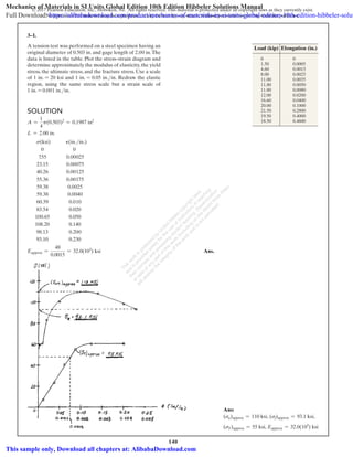
  • 1. 140 © 2017 Pearson Education, Inc., Hoboken, NJ. All rights reserved. This material is protected under all copyright laws as they currently exist. No portion of this material may be reproduced, in any form or by any means, without permission in writing from the publisher. 0 1.50 4.60 8.00 11.00 11.80 11.80 12.00 16.60 20.00 21.50 19.50 18.50 0 0.0005 0.0015 0.0025 0.0035 0.0050 0.0080 0.0200 0.0400 0.1000 0.2800 0.4000 0.4600 Load (kip) Elongation (in.) Solution A = 1 4 p(0.503)2 = 0.1987 in2 L = 2.00 in. s(ksi) P(in.>in.) 0 0 7.55 0.00025 23.15 0.00075 40.26 0.00125 55.36 0.00175 59.38 0.0025 59.38 0.0040 60.39 0.010 83.54 0.020 100.65 0.050 108.20 0.140 98.13 0.200 93.10 0.230 Eapprox = 48 0.0015 = 32.0(103 ) ksi Ans. 3–1. A tension test was performed on a steel specimen having an original diameter of 0.503 in. and gage length of 2.00 in.The data is listed in the table. Plot the stress–strain diagram and determine approximately the modulus of elasticity, the yield stress, the ultimate stress, and the fracture stress. Use a scale of 1 in. = 20 ksi and 1 in. = 0.05 in.in. Redraw the elastic region, using the same stress scale but a strain scale of 1 in. = 0.001 in.in. Ans: (su)approx = 110 ksi, (sf)approx = 93.1 ksi, (sY)approx = 55 ksi, Eapprox = 32.0(103 ) ksi This w ork is protected by U nited States copyrightlaw s and is provided solely forthe use ofinstructors in teaching theircourses and assessing studentlearning.D issem ination orsale ofany partofthis w ork (including on the W orld W ide W eb) w illdestroy the integrity ofthe w ork and is notperm itted. Mechanics of Materials in SI Units Global Edition 10th Edition Hibbeler Solutions Manual Full Download: https://alibabadownload.com/product/mechanics-of-materials-in-si-units-global-edition-10th-edition-hibbeler-solut This sample only, Download all chapters at: AlibabaDownload.com
  • 2. 141 © 2017 Pearson Education, Inc., Hoboken, NJ. All rights reserved. This material is protected under all copyright laws as they currently exist. No portion of this material may be reproduced, in any form or by any means, without permission in writing from the publisher. 3–2. Data taken from a stress–strain test for a ceramic are given in the table. The curve is linear between the origin and the first point. Plot the diagram, and determine the modulus of elasticity and the modulus of resilience. Solution Modulus of Elasticity: From the stress–strain diagram E = 33.2 - 0 0.0006 - 0 = 55.31103 2 ksi Ans. Modulus of Resilience: The modulus of resilience is equal to the area under the linear portion of the stress–strain diagram (shown shaded). ur = 1 2 (33.2)1103 2 ¢ lb in2 ≤¢0.0006 in. in. ≤ = 9.96 in # lb in3 Ans. Ans: E = 55.31103 2 ksi, ur = 9.96 in # lb in3 0 33.2 45.5 49.4 51.5 53.4 0 0.0006 0.0010 0.0014 0.0018 0.0022 S (ksi) P (in./in.) This w ork is protected by U nited States copyrightlaw s and is provided solely forthe use ofinstructors in teaching theircourses and assessing studentlearning.D issem ination orsale ofany partofthis w ork (including on the W orld W ide W eb) w illdestroy the integrity ofthe w ork and is notperm itted.
  • 3. 142 © 2017 Pearson Education, Inc., Hoboken, NJ. All rights reserved. This material is protected under all copyright laws as they currently exist. No portion of this material may be reproduced, in any form or by any means, without permission in writing from the publisher. 3–3. Data taken from a stress–strain test for a ceramic are given in the table. The curve is linear between the origin and the first point. Plot the diagram, and determine approximately the modulus of toughness.The fracture stress is sf = 53.4 ksi. Ans: (ut)approx = 85.0 in # lb in3 0 33.2 45.5 49.4 51.5 53.4 0 0.0006 0.0010 0.0014 0.0018 0.0022 S (ksi) P (in./in.) Solution Modulus of Toughness: The modulus of toughness is equal to the area under the stress–strain diagram (shown shaded). (ut)approx = 1 2 (33.2)1103 2 ¢ lb in2 ≤(0.0004 + 0.0010)¢ in. in. ≤ + 45.51103 2 ¢ lb in2 ≤(0.0012)¢ in. in. ≤ + 1 2 (7.90)1103 2 ¢ lb in2 ≤(0.0012)¢ in. in. ≤ + 1 2 (12.3)1103 2 ¢ lb in2 ≤(0.0004)¢ in. in. ≤ = 85.0 in # lb in3 Ans. This w ork is protected by U nited States copyrightlaw s and is provided solely forthe use ofinstructors in teaching theircourses and assessing studentlearning.D issem ination orsale ofany partofthis w ork (including on the W orld W ide W eb) w illdestroy the integrity ofthe w ork and is notperm itted.
  • 4. 143 © 2017 Pearson Education, Inc., Hoboken, NJ. All rights reserved. This material is protected under all copyright laws as they currently exist. No portion of this material may be reproduced, in any form or by any means, without permission in writing from the publisher. Solution Modulus of Elasticity: From the stress–strain diagram, s = 40 ksi when P = 0.001 in.in. Eapprox = 40 - 0 0.001 - 0 = 40.01103 2 ksi Ans. Yield Load: From the stress–strain diagram, sY = 40.0 ksi. PY = sYA = 40.0c a p 4 b(0.52 )d = 7.85 kip Ans. Ultimate Load: From the stress–strain diagram, su = 76.25 ksi. Pu = suA = 76.25c a p 4 b(0.52 )d = 15.0 kip Ans. *3–4. The stress–strain diagram for a steel alloy having an original diameter of 0.5 in. and a gage length of 2 in. is given in the figure. Determine approximately the modulus of elasticity for the material, the load on the specimen that causes yielding, and the ultimate load the specimen will support. 0 70 60 50 40 30 20 10 0 s (ksi) 0 0 0.280.04 0.08 0.12 0.16 0.20 0.24 0.00350.0005 0.0010.0015 0.002 0.0025 0.003 80 P (in./in.) Ans: Eapprox = 40.01103 ) ksi, PY = 7.85 kip, Pu = 15.0 kip This w ork is protected by U nited States copyrightlaw s and is provided solely forthe use ofinstructors in teaching theircourses and assessing studentlearning.D issem ination orsale ofany partofthis w ork (including on the W orld W ide W eb) w illdestroy the integrity ofthe w ork and is notperm itted.
  • 5. 144 © 2017 Pearson Education, Inc., Hoboken, NJ. All rights reserved. This material is protected under all copyright laws as they currently exist. No portion of this material may be reproduced, in any form or by any means, without permission in writing from the publisher. Solution Modulus of Elasticity: From the stress–strain diagram, s = 40 ksi when P = 0.001 in.in. E = 40 - 0 0.001 - 0 = 40.01103 ) ksi Elastic Recovery: Elastic recovery = s E = 70 40.0(103 ) = 0.00175 in.in. Thus, The amount of Elastic Recovery = 0.00175(2) = 0.00350 in. Ans. Permanent Set: Permanent set = 0.08 - 0.00175 = 0.07825 in.in. Thus, Permanent elongation = 0.07825(2) = 0.1565 in. Ans. 3–5. The stress–strain diagram for a steel alloy having an original diameter of 0.5 in. and a gage length of 2 in. is given in the figure. If the specimen is loaded until it is stressed to 70 ksi, determine the approximate amount of elastic recovery and the increase in the gage length after it is unloaded. 0 70 60 50 40 30 20 10 0 s (ksi) 0 0 0.280.04 0.08 0.12 0.16 0.20 0.24 0.00350.0005 0.0010.0015 0.002 0.0025 0.003 80 P (in./in.) Ans: Elastic recovery = 0.00350 in., Permanent elongation = 0.1565 in. This w ork is protected by U nited States copyrightlaw s and is provided solely forthe use ofinstructors in teaching theircourses and assessing studentlearning.D issem ination orsale ofany partofthis w ork (including on the W orld W ide W eb) w illdestroy the integrity ofthe w ork and is notperm itted.
  • 6. 145 © 2017 Pearson Education, Inc., Hoboken, NJ. All rights reserved. This material is protected under all copyright laws as they currently exist. No portion of this material may be reproduced, in any form or by any means, without permission in writing from the publisher. Solution Modulus of Resilience: The modulus of resilience is equal to the area under the linear portion of the stress–strain diagram. (ur)approx = 1 2 (40.0)(103 )a lb in2 b a0.001 in. in. b = 20.0 in # lb in3 Ans. Modulus of Toughness: The modulus of toughness is equal to the total area under the stress–strain diagram and can be approximated by counting the number of squares. The total number of squares is 45. (ut)approx = 45a10 kip in2 b a0.04 in. in. b = 18.0 in # kip in3 Ans. 3–6. The stress–strain diagram for a steel alloy having an original diameter of 0.5 in. and a gage length of 2 in. is given in the figure. Determine approximately the modulus of resilience and the modulus of toughness for the material. 0 70 60 50 40 30 20 10 0 s (ksi) 0 0 0.280.04 0.08 0.12 0.16 0.20 0.24 0.00350.0005 0.0010.0015 0.002 0.0025 0.003 80 P (in./in.) Ans: (ur)approx = 20.0 in # lb in3 , (ut)approx = 18.0 in # kip in3 This w ork is protected by U nited States copyrightlaw s and is provided solely forthe use ofinstructors in teaching theircourses and assessing studentlearning.D issem ination orsale ofany partofthis w ork (including on the W orld W ide W eb) w illdestroy the integrity ofthe w ork and is notperm itted.
  • 7. 146 © 2017 Pearson Education, Inc., Hoboken, NJ. All rights reserved. This material is protected under all copyright laws as they currently exist. No portion of this material may be reproduced, in any form or by any means, without permission in writing from the publisher. Solution +ΣMC = 0;  FAB sin 30°(10) - 0.1(10)(5) = 0; FAB = 1.0 kip sAB = FAB AAB = 1.0 p 4 (0.2)2 = 31.83 ksi s = EP;  31.83 = 29(103 ) PAB;  PAB = 0.0010981 in.in. dAB = PAB LAB = 0.0010981a 120 cos 30° b = 0.152 in. Ans. 3–7. The rigid beam is supported by a pin at C and an A-36 steel guy wire AB. If the wire has a diameter of 0.2 in., determine how much it stretches when a distributed load of w = 100 lbft acts on the beam.The material remains elastic. 30Њ 10 ft C A B w Ans: dAB = 0.152 in. This w ork is protected by U nited States copyrightlaw s and is provided solely forthe use ofinstructors in teaching theircourses and assessing studentlearning.D issem ination orsale ofany partofthis w ork (including on the W orld W ide W eb) w illdestroy the integrity ofthe w ork and is notperm itted.
  • 8. 147 © 2017 Pearson Education, Inc., Hoboken, NJ. All rights reserved. This material is protected under all copyright laws as they currently exist. No portion of this material may be reproduced, in any form or by any means, without permission in writing from the publisher. Solution sin u = 0.0625 10 ; u = 0.3581° a = 90 + 0.3581° = 90.3581° AB = 10 cos 30° = 11.5470 ft AB′ = 2102 + 5.77352 - 2(10)(5.7735) cos 90.3581° = 11.5782 ft PAB = AB′ - AB AB = 11.5782 - 11.5470 11.5470 = 0.002703 in.in. sAB = EPAB = 29(103 )(0.002703) = 78.38 ksi FAB = sAB AAB = 78.38 a p 4 b(0.2)2 = 2.462 kip + ΣMC = 0;  2.462 sin 30°(10) - 10w(5) = 0; w = 0.246 kipft Ans. *3–8. The rigid beam is supported by a pin at C and an A-36 steel guy wire AB. If the wire has a diameter of 0.2 in., determine the distributed load w if the end B is displaced 0.75 in. downward. 30Њ 10 ft C A B w Ans: w = 0.246 kipft This w ork is protected by U nited States copyrightlaw s and is provided solely forthe use ofinstructors in teaching theircourses and assessing studentlearning.D issem ination orsale ofany partofthis w ork (including on the W orld W ide W eb) w illdestroy the integrity ofthe w ork and is notperm itted.
  • 9. 148 © 2017 Pearson Education, Inc., Hoboken, NJ. All rights reserved. This material is protected under all copyright laws as they currently exist. No portion of this material may be reproduced, in any form or by any means, without permission in writing from the publisher. Solution s = P A = 2.5 0.875 = 2.857 ksi s = 9.5(103 )P13 2.857(103 ) = 9.5(103 )P13 P = 0.0272 in.in. d = LP = 3(12)(0.0272) = 0.979 in. Ans. 3–9. Acetal plastic has a stress–strain diagram as shown. If a bar of this material has a length of 3 ft and cross-sectional area of 0.875 in2, and is subjected to an axial load of 2.5 kip, determine its elongation. P (in./in.) ␴ ϭ 9.5(103 )P1/3 ␴ (psi) Ans: d = 0.979 in. This w ork is protected by U nited States copyrightlaw s and is provided solely forthe use ofinstructors in teaching theircourses and assessing studentlearning.D issem ination orsale ofany partofthis w ork (including on the W orld W ide W eb) w illdestroy the integrity ofthe w ork and is notperm itted.
  • 10. 149 © 2017 Pearson Education, Inc., Hoboken, NJ. All rights reserved. This material is protected under all copyright laws as they currently exist. No portion of this material may be reproduced, in any form or by any means, without permission in writing from the publisher. 3–10. The stress–strain diagram for an aluminum alloy specimen having an original diameter of 0.5 in. and a gage length of  2  in. is given in the figure. Determine approximately the modulus of elasticity for the material, the load on the specimen that causes yielding, and the ultimate load the specimen will support. Solution Modulus of Elasticity: From the stress–strain diagram, s = 50.0 ksi when P = 0.005 in.in. Thus Eapprox = 50.0 - 0 0.005 - 0 = 10.0(103 ) ksi Ans. Yield Load: From the stress–strain diagram, sy = 50.0 ksi.Thus PY = syA = 50.0c p 4 (0.52 ) d = 9.82 kip Ans. Ultimate Load: From the stress–strain diagram, su = 68.0 ksi. Thus, Pu = suA = 68.0c p 4 (0.52 ) d = 13.4 kip Ans. 0 70 60 50 40 30 20 10 00 0 0.140.02 0.04 0.06 0.08 0.10 0.12 0.01750.0025 0.0050.0075 0.01 0.01250.015 P (in./in.) s (ksi) 0.16 0.18 0.2 0.02 0.02550.025 Ans: Eapprox = 10.0(103 ) ksi, PY = 9.82 kip, Pu = 13.4 kip This w ork is protected by U nited States copyrightlaw s and is provided solely forthe use ofinstructors in teaching theircourses and assessing studentlearning.D issem ination orsale ofany partofthis w ork (including on the W orld W ide W eb) w illdestroy the integrity ofthe w ork and is notperm itted.
  • 11. 150 © 2017 Pearson Education, Inc., Hoboken, NJ. All rights reserved. This material is protected under all copyright laws as they currently exist. No portion of this material may be reproduced, in any form or by any means, without permission in writing from the publisher. 3–11. The stress–strain diagram for an aluminum alloy specimen having an original diameter of 0.5 in. and a gage length of 2 in. is given in the figure. If the specimen is loaded until it is stressed to 60 ksi, determine the approximate amount of elastic recovery and the increase in the gage length after it is unloaded. Solution Modulus of Elasticity: From the stress–strain diagram, s = 50.0 ksi when P = 0.005 in.in. Thus Eapprox = 50.0 - 0 0.005 - 0 = 10.0(103 ) ksi Elastic Recovery and Permanent Set: From the stress–strain diagram, s = 60 ksi when P = 0.04 in.in. Thus s E = 60 10.0(103 ) = 0.006 in.in. Thus, Elastic Recovery = (0.006)(2) = 0.012 in. Ans. And Permanent set = 0.04 - 0.006 = 0.034 in.in. Then Permanent elongation = 0.034(2) = 0.0680 in. Ans. 0 70 60 50 40 30 20 10 00 0 0.140.02 0.04 0.06 0.08 0.10 0.12 0.01750.0025 0.0050.0075 0.01 0.01250.015 P (in./in.) s (ksi) 0.16 0.18 0.2 0.02 0.02550.025 Ans: Elastic recovery = 0.012 in., Permanent elongation = 0.0680 in. This w ork is protected by U nited States copyrightlaw s and is provided solely forthe use ofinstructors in teaching theircourses and assessing studentlearning.D issem ination orsale ofany partofthis w ork (including on the W orld W ide W eb) w illdestroy the integrity ofthe w ork and is notperm itted.
  • 12. 151 © 2017 Pearson Education, Inc., Hoboken, NJ. All rights reserved. This material is protected under all copyright laws as they currently exist. No portion of this material may be reproduced, in any form or by any means, without permission in writing from the publisher. *3–12. The stress–strain diagram for an aluminum alloy specimen having an original diameter of 0.5 in. and a gage length of 2 in. is given in the figure. Determine approximately the modulus of resilience and the modulus of toughness for the material. Solution Modulus of Resilience: The modulus of resilience is equal to the area under the linear portion of the stress–strain diagram. (ur)approx = 1 2 350.0(103 )lbin2 4(0.005 in.in.) = 125 in # lb in3 Ans. Modulus of Toughness: The modulus of toughness is equal to the entire area under the stress–strain diagram, which can be approximated by counting the number of squares.The total number of squares is 63. (ut)approx = 63(10.0 kipin2 )(0.02 in.in.) = 12.6 in # kip in3 Ans. 0 70 60 50 40 30 20 10 00 0 0.140.02 0.04 0.06 0.08 0.10 0.12 0.01750.0025 0.0050.0075 0.01 0.01250.015 P (in./in.) s (ksi) 0.16 0.18 0.2 0.02 0.02550.025 Ans: (ur)approx = 125 in # lb in3 , (ut)approx = 12.6 in # kip in3 This w ork is protected by U nited States copyrightlaw s and is provided solely forthe use ofinstructors in teaching theircourses and assessing studentlearning.D issem ination orsale ofany partofthis w ork (including on the W orld W ide W eb) w illdestroy the integrity ofthe w ork and is notperm itted.
  • 13. 152 © 2017 Pearson Education, Inc., Hoboken, NJ. All rights reserved. This material is protected under all copyright laws as they currently exist. No portion of this material may be reproduced, in any form or by any means, without permission in writing from the publisher. Solution Normal Stress and Strain: s = P A = 8.00 0.7 = 11.43 ksi P = d L = 0.002 5 = 0.000400 in.in. Modulus of Elasticity: E = s P = 11.43 0.000400 = 28.6(103 ) ksi Ans. 3–13.  A bar having a length of 5 in. and cross-sectional area of 0.7 in.2 is subjected to an axial force of 8000 lb. If the bar stretches 0.002 in., determine the modulus of elasticity of the material.The material has linear elastic behavior. 8000 lb8000 lb 5 in. Ans: E = 28.6(103 ) ksi This w ork is protected by U nited States copyrightlaw s and is provided solely forthe use ofinstructors in teaching theircourses and assessing studentlearning.D issem ination orsale ofany partofthis w ork (including on the W orld W ide W eb) w illdestroy the integrity ofthe w ork and is notperm itted.
  • 14. 153 © 2017 Pearson Education, Inc., Hoboken, NJ. All rights reserved. This material is protected under all copyright laws as they currently exist. No portion of this material may be reproduced, in any form or by any means, without permission in writing from the publisher. Solution Here, we are only interested in determining the force in wire BD. Referring to the FBD in Fig. a a+ΣMA = 0;  FBD14 5 2(3) - 600(6) = 0  FBD = 1500 lb The normal stress developed in the wire is sBD = FBD ABD = 1500 p 4 (0.252 ) = 30.56(103 ) psi = 30.56 ksi Since sBD 6 sy = 36 ksi, Hooke’s Law can be applied to determine the strain in the wire. sBD = EPBD;  30.56 = 29.0(103 )PBD      PBD = 1.054(10-3 ) in.in. The unstretched length of the wire is LBD = 232 + 42 = 5 ft = 60 in. Thus, the wire stretches dBD = PBD LBD = 1.054(10-3 )(60) = 0.0632 in. Ans. 3–14.  The rigid pipe is supported by a pin at A and an A-36 steel guy wire BD. If the wire has a diameter of 0.25 in.,determine how much it stretches when a load of P = 600 lb acts on the pipe. 3 ft 3 ft C DA B P4 ft Ans: dBD = 0.0632 in. This w ork is protected by U nited States copyrightlaw s and is provided solely forthe use ofinstructors in teaching theircourses and assessing studentlearning.D issem ination orsale ofany partofthis w ork (including on the W orld W ide W eb) w illdestroy the integrity ofthe w ork and is notperm itted.
  • 15. 154 © 2017 Pearson Education, Inc., Hoboken, NJ. All rights reserved. This material is protected under all copyright laws as they currently exist. No portion of this material may be reproduced, in any form or by any means, without permission in writing from the publisher. Solution Here, we are only interested in determining the force in wire BD. Referring to the FBD in Fig. a   a+ΣMA = 0;  FBD14 5 2(3) - P(6) = 0  FBD = 2.50 P The unstretched length for wire BD is LBD = 232 + 42 = 5 ft = 60 in. From the geometry shown in Fig. b, the stretched length of wire BD is LBD′ = 2602 + 0.0752 - 2(60)(0.075) cos 143.13° = 60.060017 Thus, the normal strain is  PBD = LBD′ - LBD LBD = 60.060017 - 60 60 = 1.0003(10-3 ) in.in. Then, the normal stress can be obtain by applying Hooke’s Law. sBD = EPBD = 29(103 )31.0003(10-3 )4 = 29.01 ksi Since sBD 6 sy = 36 ksi, the result is valid. sBD = FBD ABD ; 29.01(103 ) = 2.50 P p 4 (0.252 ) P = 569.57 lb = 570 lb Ans. 3–15.  The rigid pipe is supported by a pin at A and an A-36 guy wire BD. If the wire has a diameter of 0.25 in., determine the load P if the end C is displaced 0.075 in. downward. 3 ft 3 ft C DA B P4 ft Ans: P = 570 lb This w ork is protected by U nited States copyrightlaw s and is provided solely forthe use ofinstructors in teaching theircourses and assessing studentlearning.D issem ination orsale ofany partofthis w ork (including on the W orld W ide W eb) w illdestroy the integrity ofthe w ork and is notperm itted.
  • 16. 155 © 2017 Pearson Education, Inc., Hoboken, NJ. All rights reserved. This material is protected under all copyright laws as they currently exist. No portion of this material may be reproduced, in any form or by any means, without permission in writing from the publisher. Solution Stress–Strain Relationship: From the stress–strain diagram with P = 0.1 mmmm 7 0.0015 mmmm s - 450 0.1 - 0.0015 = 600 - 450 0.3 - 0.0015 s = 499.497 MPa Axial Force: For each head P = sA = 499.4971(106 )(1.5)(10-6 ) = 749.24 N Thus, the tension in the bolt is T = 6 P = 6(749.24) = 4495 N = 4.50 kN Ans. *3–16.  Direct tension indicators are sometimes used instead of torque wrenches to ensure that a bolt has a prescribed tension when used for connections. If a nut on the bolt is tightened so that the six 3-mm high heads of the indicator are strained 0.1 mmmm, and leave a contact area on each head of 1.5 mm2, determine the tension in the bolt shank. The material has the stress–strain diagram shown. 3 mm s (MPa) P (mm/mm) 0.30.0015 600 450 Ans: T = 4.50 kN This w ork is protected by U nited States copyrightlaw s and is provided solely forthe use ofinstructors in teaching theircourses and assessing studentlearning.D issem ination orsale ofany partofthis w ork (including on the W orld W ide W eb) w illdestroy the integrity ofthe w ork and is notperm itted.
  • 17. 156 © 2017 Pearson Education, Inc., Hoboken, NJ. All rights reserved. This material is protected under all copyright laws as they currently exist. No portion of this material may be reproduced, in any form or by any means, without permission in writing from the publisher. Solution Support Reactions: Referring to the FBD of the beam, Fig. a, a+ΣMC = 0; FAB cos 30°(10) - 0.2(10)(5) = 0 FAB = 1.1547 kip Normal Stress and Strain Relation: The normal stress is sAB = FAB AAB = 1.1547 p 4 (0.22 ) = 36.76 ksi For structural A992 steel alloy, Est = 29.0(103 ) ksi. s = EP; 36.76 = 29.0(103 )PAB PAB = 0.001267 in.in. Thus, dAB = PABLAB = (0.001267 in.in.) (72 in.) = 0.0913 in. Ans. 3–17.  The rigid beam is supported by a pin at C and an A992 steel guy wire AB of length 6 ft. If the wire has a diameter of 0.2 in., determine how much it stretches when a distributed load of w = 200 lbft acts on the beam. The wire remains elastic. 30Њ 10 ft C A B w Ans: dAB = 0.0913 in. This w ork is protected by U nited States copyrightlaw s and is provided solely forthe use ofinstructors in teaching theircourses and assessing studentlearning.D issem ination orsale ofany partofthis w ork (including on the W orld W ide W eb) w illdestroy the integrity ofthe w ork and is notperm itted.
  • 18. 157 © 2017 Pearson Education, Inc., Hoboken, NJ. All rights reserved. This material is protected under all copyright laws as they currently exist. No portion of this material may be reproduced, in any form or by any means, without permission in writing from the publisher. Solution Support Reactions: Referring to the FBD of the beam, Fig. a, a+ ΣMC = 0; FAB cos 30°(10) - 10w(5) = 0 FAB = 1023 3 w Normal Stress and Strain Relation: Referring to the geometry shown in Fig. b, and applying cosine law and sine law, LAC = 2102 + 62 - 2(10)(6)cos 120° = 14 ft sin f 6 = sin 120° 14 ; f = 21.7868° sin u = 0.01 10 ; u = 0.05730° Thus, LAB′ = 2142 + 102 - 2(14)(10) cos (21.7868° + 0.05730°) = 6.008665 ft Then PAB = LAB′ - LAB LAB = 6.008665 - 6 6 = 0.001444 in.in. For structural A992 steel alloy, Est = 29.0(103 ) ksi.Thus, sAB = EPAB = 29(103 )(0.001444) = 41.88 ksi 6 50 ksi (O.K!) FAB = sABAAB; 1023 3 w = (41.88)c p 4 (0.22 ) d w = 0.2279 kipft = 228 lbft Ans. 3–18.  The rigid beam is supported by a pin at C and an A992 steel guy wire AB of length 6 ft. If the wire has a diameter of 0.2 in., determine the distributed load w if the end B is displaced 0.12 in. downward.The wire remains elastic. 30Њ 10 ft C A B w Ans: w = 228 lbft This w ork is protected by U nited States copyrightlaw s and is provided solely forthe use ofinstructors in teaching theircourses and assessing studentlearning.D issem ination orsale ofany partofthis w ork (including on the W orld W ide W eb) w illdestroy the integrity ofthe w ork and is notperm itted.
  • 19. 158 © 2017 Pearson Education, Inc., Hoboken, NJ. All rights reserved. This material is protected under all copyright laws as they currently exist. No portion of this material may be reproduced, in any form or by any means, without permission in writing from the publisher. Solution P = 0.45(10-6 )s + 0.36(10-12 )s3 , dP = 10.45(10-6 ) + 1.08(10-12 ) s2 2ds E = ds dP ` s=0 = 1 0.45(10-6 ) = 2.22(106 ) kPa = 2.22 GPa The equation for the recovery line is s = 2.22(106 )(P - 0.003). This line intersects the stress–strain curve at sYS = 2027 kPa = 2.03 MPa Ans. 3–19.  The stress–strain diagram for a bone is shown, and can be described by the equation P = 0.45110-6 2 s + 0.36110-12 2 s3 , where s is in kPa. Determine the yield strength assuming a 0.3% offset. P P P ϭ 0.45(10Ϫ6 )s + 0.36(10Ϫ12 )s3 P s Ans: sYS = 2.03 MPa This w ork is protected by U nited States copyrightlaw s and is provided solely forthe use ofinstructors in teaching theircourses and assessing studentlearning.D issem ination orsale ofany partofthis w ork (including on the W orld W ide W eb) w illdestroy the integrity ofthe w ork and is notperm itted.
  • 20. 159 © 2017 Pearson Education, Inc., Hoboken, NJ. All rights reserved. This material is protected under all copyright laws as they currently exist. No portion of this material may be reproduced, in any form or by any means, without permission in writing from the publisher. Solution When P = 0.12 120(10-3 ) = 0.45 s + 0.36(10-6 )s3 Solving for the real root: s = 6873.52 kPa ut = LA dA = L 6873.52 0 (0.12 - P)ds ut = L 6873.52 0 (0.12 - 0.45(10-6 )s - 0.36(10-12 )s3 )ds = 0.12 s - 0.225(10-6 )s2 - 0.09(10-12 )s4 ͉ 6873.52 0 = 613 kJm3 Ans. d = PL = 0.12(200) = 24 mm Ans. *3–20.  The stress–strain diagram for a bone is shown and can be described by the equation P = 0.45110-6 2 s + 0.36110-12 2 s3 , where s is in kPa. Determine the modulus of toughness and the amount of elongation of a 200-mm-long region just before it fractures if failure occurs at P = 0.12 mmmm. P P P ϭ 0.45(10Ϫ6 )s + 0.36(10Ϫ12 )s3 P s Ans: ut = 613 kJm3 , d = 24 mm This w ork is protected by U nited States copyrightlaw s and is provided solely forthe use ofinstructors in teaching theircourses and assessing studentlearning.D issem ination orsale ofany partofthis w ork (including on the W orld W ide W eb) w illdestroy the integrity ofthe w ork and is notperm itted.
  • 21. 160 © 2017 Pearson Education, Inc., Hoboken, NJ. All rights reserved. This material is protected under all copyright laws as they currently exist. No portion of this material may be reproduced, in any form or by any means, without permission in writing from the publisher. Solution + c gFy = 0;   3 5 FAB - P = 0; FAB = 1.6667 P (1) d+ ΣFx = 0; FBC - 4 5 (1.6667P) = 0;    FBC = 1.333 P (2) Assuming failure of bar BC: From the stress–strain diagram (sR)t = 5 ksi s = FBC ABC ; 5 = FBC 4 ; FBC = 20.0 kip From Eq. (2), P = 15.0 kip Assuming failure of bar AB: From stress–strain diagram (sR)c = 25.0 ksi s = FAB AAB ; 25.0 = FAB 1.5 ; FAB = 37.5 kip From Eq. (1), P = 22.5 kip Choose the smallest value: P = 15.0 kip Ans. 3–21.  The two bars are made of a material that has the stress– strain diagram shown. If the cross-sectional area of bar AB is 1.5 in2 and BC is 4 in2, determine the largest force P that can be supported before any member fractures. Assume that buckling does not occur. P C B A 3 ft 4 ft P (10 ) (in./in.) s (ksi) 5 0 10 15 20 25 0.750.600.400.200 tension compression –3 Ans: P = 15.0 kip This w ork is protected by U nited States copyrightlaw s and is provided solely forthe use ofinstructors in teaching theircourses and assessing studentlearning.D issem ination orsale ofany partofthis w ork (including on the W orld W ide W eb) w illdestroy the integrity ofthe w ork and is notperm itted.
  • 22. 161 © 2017 Pearson Education, Inc., Hoboken, NJ. All rights reserved. This material is protected under all copyright laws as they currently exist. No portion of this material may be reproduced, in any form or by any means, without permission in writing from the publisher. Solution + cΣFy = 0;    FBAa 3 5 b - 3 = 0;    FBA = 5 kip +S ΣFx = 0;    -FBC + 5a 4 5 b = 0;   FBC = 4 kip For member BC: (smax)t = FBC ABC ; ABC = 4 kip 5 ksi = 0.8 in2 Ans. For member BA: (smax)c = FBA ABA ; ABA = 5 kip 25 ksi = 0.2 in2 Ans. 3–22.  The two bars are made of a material that has the stress– strain diagram shown. Determine the cross-sectional area of each bar so that the bars fracture simultaneously when the load P = 3 kip.Assume that buckling does not occur. P C B A 3 ft 4 ft P (10 ) (in./in.) s (ksi) 5 0 10 15 20 25 0.750.600.400.200 tension compression –3 Ans: ABC = 0.8 in2 , ABA = 0.2 in2 This w ork is protected by U nited States copyrightlaw s and is provided solely forthe use ofinstructors in teaching theircourses and assessing studentlearning.D issem ination orsale ofany partofthis w ork (including on the W orld W ide W eb) w illdestroy the integrity ofthe w ork and is notperm itted.
  • 23. 162 © 2017 Pearson Education, Inc., Hoboken, NJ. All rights reserved. This material is protected under all copyright laws as they currently exist. No portion of this material may be reproduced, in any form or by any means, without permission in writing from the publisher. Solution sAB = FAB AAB = 2.857 p 4 (0.22 ) = 90.94 ksi PAB = sAB E = 90.94 29(103 ) = 0.003136 dAB = PAB LAB = 0.003136 a 7(12) cos 30° b = 0.304 in. Ans. 3–23. The pole is supported by a pin at C and an A-36 steel guy wire AB. If the wire has a diameter of 0.2 in., determine how much it stretches when a horizontal force of 2.5 kip acts on the pole. 30 3 ft 4 ft CA 2.5 kip B Ans: dAB = 0.304 in. This w ork is protected by U nited States copyrightlaw s and is provided solely forthe use ofinstructors in teaching theircourses and assessing studentlearning.D issem ination orsale ofany partofthis w ork (including on the W orld W ide W eb) w illdestroy the integrity ofthe w ork and is notperm itted.
  • 24. 163 © 2017 Pearson Education, Inc., Hoboken, NJ. All rights reserved. This material is protected under all copyright laws as they currently exist. No portion of this material may be reproduced, in any form or by any means, without permission in writing from the publisher. Solution 3 0.025 = 7 d d = 0.0417 in. PDE = d L = 0.0417 3(12) = 0.00116 in.in. Ans. sDE = EPDE = 29(103 )(0.00116) = 33.56 ksi FDE = sDEADE = 33.56(0.002) = 0.0672 kip a+ ΣMA = 0;  -(0.0672)(5) + 3(W) = 0 W = 0.112 kip = 112 lb Ans. sBC = W ABC = 0.112 0.002 = 55.94 ksi PBC = sBC E = 55.94 29(103 ) = 0.00193 in.in. Ans. *3–24. The bar DA is rigid and is originally held in the horizontal position when the weight W is supported from C. If the weight causes B to displace downward 0.025 in., determine the strain in wires DE and BC.Also, if the wires are made of A-36 steel and have a cross-sectional area of 0.002 in2, determine the weight W. 2 ft 3 ft 4 ft 3 ft D AB E C W Ans: PDE = 0.00116 in.in., W = 112 lb, PBC = 0.00193 in.in. This w ork is protected by U nited States copyrightlaw s and is provided solely forthe use ofinstructors in teaching theircourses and assessing studentlearning.D issem ination orsale ofany partofthis w ork (including on the W orld W ide W eb) w illdestroy the integrity ofthe w ork and is notperm itted.
  • 25. 164 © 2017 Pearson Education, Inc., Hoboken, NJ. All rights reserved. This material is protected under all copyright laws as they currently exist. No portion of this material may be reproduced, in any form or by any means, without permission in writing from the publisher. Solution s = P A = 300 p 4(0.015)2 = 1.678 MPa Plong = s E = 1.678(106 ) 2.70(109 ) = 0.0006288 d = Plong L = 0.0006288(200) = 0.126 mm Ans. Plat = -nPlong = -0.4(0.0006288) = -0.0002515 ∆d = Platd = -0.0002515(15) = -0.00377 mm Ans. 3–25. The acrylic plastic rod is 200 mm long and 15 mm in diameter. If an axial load of 300 N is applied to it, determine the change in its length and the change in its diameter. Ep = 2.70 GPa, np = 0.4. 300 N 200 mm 300 N Ans: d = 0.126 mm, ∆d = -0.00377 mm This w ork is protected by U nited States copyrightlaw s and is provided solely forthe use ofinstructors in teaching theircourses and assessing studentlearning.D issem ination orsale ofany partofthis w ork (including on the W orld W ide W eb) w illdestroy the integrity ofthe w ork and is notperm itted.
  • 26. 165 © 2017 Pearson Education, Inc., Hoboken, NJ. All rights reserved. This material is protected under all copyright laws as they currently exist. No portion of this material may be reproduced, in any form or by any means, without permission in writing from the publisher. Solution Plat = d′ - d d = 32 - 30 30 = 0.06667 mmmm v = - Plat Plong ;  Plong = - Plat v = - 0.06667 0.45 = -0.1481 mmmm p = s = E Plong = 5(106 )(0.1481) = 741 kPa Ans. d = ͉Plong L ͉ = ͉ -0.1481(50) ͉ = 7.41 mm Ans. 3–26. The plug has a diameter of 30 mm and fits within a rigid sleeve having an inner diameter of 32 mm. Both the plug and the sleeve are 50 mm long. Determine the axial pressure p that must be applied to the top of the plug to cause it to contact the sides of the sleeve. Also, how far must the plug be compressed downward in order to do this? The plug is made from a material for which E = 5 MPa, n = 0.45. p Ans: p = 741 kPa, d = 7.41 mm This w ork is protected by U nited States copyrightlaw s and is provided solely forthe use ofinstructors in teaching theircourses and assessing studentlearning.D issem ination orsale ofany partofthis w ork (including on the W orld W ide W eb) w illdestroy the integrity ofthe w ork and is notperm itted.
  • 27. 166 © 2017 Pearson Education, Inc., Hoboken, NJ. All rights reserved. This material is protected under all copyright laws as they currently exist. No portion of this material may be reproduced, in any form or by any means, without permission in writing from the publisher. 3–27. The elastic portion of the stress–strain diagram for an aluminum alloy is shown in the figure. The specimen from which it was obtained has an original diameter of 12.7 mm and a gage length of 50.8 mm.When the applied load on the specimen is 50 kN, the diameter is 12.67494 mm. Determine Poisson’s ratio for the material. 490 P (mm/mm) 0.007 s (MPa) Solution Average Normal Stress: s = N A = 50(103 ) p 4 (0.01272 ) = 394.71(106 ) Pa = 394.71 MPa Average Normal Strain: Referring to the stress–strain diagram, the modulus of elasticity is E = 490(106 ) 0.007 = 70.0(109 ) Pa = 70.0 GPa. Plong = s E = 394.71(106 ) 70.0(109 ) = 0.0056386 mmmm Plat = d - d0 d0 = 12.67494 - 12.7 12.7 = -0.0019732 Poisson’s Ratio: The lateral and longitudinal strain can be related using Poisson’s ratio, that is n = - Plat Plong = - (-0.019732) 0.0056386 = 0.350 Ans. Ans: n = 0.350 This w ork is protected by U nited States copyrightlaw s and is provided solely forthe use ofinstructors in teaching theircourses and assessing studentlearning.D issem ination orsale ofany partofthis w ork (including on the W orld W ide W eb) w illdestroy the integrity ofthe w ork and is notperm itted.
  • 28. 167 © 2017 Pearson Education, Inc., Hoboken, NJ. All rights reserved. This material is protected under all copyright laws as they currently exist. No portion of this material may be reproduced, in any form or by any means, without permission in writing from the publisher. *3–28. The elastic portion of the stress–strain diagram for an aluminum alloy is shown in the figure. The specimen from which it was obtained has an original diameter of 12.7 mm and a gage length of 50.8 mm. If a load of P = 60 kN is applied to the specimen, determine its new diameter and length.Take n = 0.35. 490 P (mm/mm) 0.007 s (MPa) Solution Average Normal Stress: s = N A = 60(103 ) p 4 (0.01272 ) = 473.65(106 ) Pa = 473.65 MPa Average Normal Strain: Referring to the stress–strain diagram, the modulus of elasticity is E = 490(106 ) 0.007 = 70.0(109 ) Pa = 70.0 GPa. Plong = s E = 473.65(106 ) 70.0(109 ) = 0.0067664 mmmm Thus, dL = Plong L0 = 0.0067664(50.8) = 0.34373 mm Then L = L0 + dL = 50.8 + 0.34373 = 51.1437 mm Ans. Poisson’s Ratio: The lateral strain can be related to the longitudinal strain using Poisson’s ratio. Plat = -nPlong = -0.35(0.0067664) = -0.0023682 mmmm Thus, dd = Plat d = -0.0023682(12.7) = -0.030077 mm Then d = d0 + dd = 12.7 + (-0.030077) = 12.66992 mm = 12.67 mm Ans. Ans: L = 51.1437 mm, d = 12.67 mm This w ork is protected by U nited States copyrightlaw s and is provided solely forthe use ofinstructors in teaching theircourses and assessing studentlearning.D issem ination orsale ofany partofthis w ork (including on the W orld W ide W eb) w illdestroy the integrity ofthe w ork and is notperm itted.
  • 29. 168 © 2017 Pearson Education, Inc., Hoboken, NJ. All rights reserved. This material is protected under all copyright laws as they currently exist. No portion of this material may be reproduced, in any form or by any means, without permission in writing from the publisher. Solution Average Shear Stress: The shear force is V = 50 N. t = V A = 50 0.02(0.05) = 50.0 kPa Shear-Stress – Strain Relationship: Applying Hooke’s law for shear t = G g 50.0(103 ) = 0.2(106 ) g g = 0.250 rad Ans. 3–29. The brake pads for a bicycle tire are made of rubber. If a frictional force of 50 N is applied to each side of the tires, determine the average shear strain in the rubber. Each pad has cross-sectional dimensions of 20 mm and 50 mm. Gr = 0.20 MPa. 50 mm 10 mm 10 mm Ans: g = 0.250 rad This w ork is protected by U nited States copyrightlaw s and is provided solely forthe use ofinstructors in teaching theircourses and assessing studentlearning.D issem ination orsale ofany partofthis w ork (including on the W orld W ide W eb) w illdestroy the integrity ofthe w ork and is notperm itted.
  • 30. 169 © 2017 Pearson Education, Inc., Hoboken, NJ. All rights reserved. This material is protected under all copyright laws as they currently exist. No portion of this material may be reproduced, in any form or by any means, without permission in writing from the publisher. 3–30. The lap joint is connected together using a 1.25 in. diameter bolt. If the bolt is made from a material having a shear stress–strain diagram that is approximated as shown, determine the shear strain developed in the shear plane of the bolt when P = 75 kip. 50 0.005 0.05 75 t (ksi) g (rad) P 2 P P 2 Solution Internal Loadings: The shear force developed in the shear planes of the bolt can be determined by considering the equilibrium of the free-body diagram shown in Fig. a. +S ΣFx = 0;      75 - 2V = 0   V = 37.5 kip Shear Stress and Strain: t = V A = 37.5 p 4 11.252 2 = 30.56 ksi Using this result, the corresponding shear strain can be obtained from the shear stress–strain diagram, Fig. b. 30.56 g = 50 0.005 ; g = 3.06(10-3 ) rad Ans. Ans: g = 3.06(10-3 ) rad This w ork is protected by U nited States copyrightlaw s and is provided solely forthe use ofinstructors in teaching theircourses and assessing studentlearning.D issem ination orsale ofany partofthis w ork (including on the W orld W ide W eb) w illdestroy the integrity ofthe w ork and is notperm itted.
  • 31. 170 © 2017 Pearson Education, Inc., Hoboken, NJ. All rights reserved. This material is protected under all copyright laws as they currently exist. No portion of this material may be reproduced, in any form or by any means, without permission in writing from the publisher. 3–31. The lap joint is connected together using a 1.25 in. diameter bolt. If the bolt is made from a material having a shear stress–strain diagram that is approximated as shown, determine the permanent shear strain in the shear plane of the bolt when the applied force P = 150 kip is removed. 50 0.005 0.05 75 t (ksi) g (rad) P 2 P P 2 Solution Internal Loadings: The shear force developed in the shear planes of the bolt can be determined by considering the equilibrium of the free-body diagram shown in Fig. a. +S ΣFx = 0;      150 - 2V = 0      V = 75 kip Shear Stress and Strain: t = V A = 75 p 4 11.252 2 = 61.12 ksi Using this result, the corresponding shear strain can be obtained from the shear stress–strain diagram, Fig. b. 61.12 - 50 g - 0.005 = 75 - 50 0.05 - 0.005 ; g = 0.02501 rad When force P is removed, the shear strain recovers linearly along line BC, Fig. b, with a slope that is the same as line OA.This slope represents the shear modulus. G = 50 0.005 = 10(103 ) ksi Thus, the elastic recovery of shear strain is t = Ggr; 61.12 = (10)(103 )gr gr = 6.112(10-3 ) rad And the permanent shear strain is gP = g - gr = 0.02501 - 6.112(10-3 ) = 0.0189 rad Ans. Ans: gP = 0.0189 rad This w ork is protected by U nited States copyrightlaw s and is provided solely forthe use ofinstructors in teaching theircourses and assessing studentlearning.D issem ination orsale ofany partofthis w ork (including on the W orld W ide W eb) w illdestroy the integrity ofthe w ork and is notperm itted.
  • 32. 171 © 2017 Pearson Education, Inc., Hoboken, NJ. All rights reserved. This material is protected under all copyright laws as they currently exist. No portion of this material may be reproduced, in any form or by any means, without permission in writing from the publisher. Ans: Px = 0.0075 in.in., Py = -0.00375 in.in., gxy = 0.0122 rad Solution Px = dL L = 0.03 4 = 0.0075 in.in. Ans. Py = -nPx = -0.5(0.0075) = -0.00375 in.in. Ans. gxy = p 2 - u = p 2 - 89.3°a p 180° b = 0.0122 rad Ans. *3–32. The rubber block is subjected to an elongation of 0.03 in. along the x axis, and its vertical faces are given a tilt so that u = 89.3°. Determine the strains Px, Py and gxy.Take nr = 0.5. 3 in. y x θ 4 in. This w ork is protected by U nited States copyrightlaw s and is provided solely forthe use ofinstructors in teaching theircourses and assessing studentlearning.D issem ination orsale ofany partofthis w ork (including on the W orld W ide W eb) w illdestroy the integrity ofthe w ork and is notperm itted.
  • 33. 172 © 2017 Pearson Education, Inc., Hoboken, NJ. All rights reserved. This material is protected under all copyright laws as they currently exist. No portion of this material may be reproduced, in any form or by any means, without permission in writing from the publisher. Solution Modulus of Rigidity: From the stress –strain diagram, G = 50 0.004 = 12.5(103 ) ksi Modulus of Elasticity: G = E 2(1 + n) 12.5(103 ) = E 2(1 + 0.3) E = 32.5(103 ) ksi Ans. Yielding Shear: The bolt is subjected to a yielding shear of Vg = P. From the stress – strain diagram, tg = 50 ksi tg = Vg A 50 = P p 4 (0.252 ) P = 2.45 kip Ans. 3–33. The shear stress–strain diagram for an alloy is shown in the figure. If a bolt having a diameter of 0.25 in. is made of this material and used in the lap joint, determine the modulus of elasticity E and the force P required to cause the material to yield.Take n = 0.3. P P 0.004 tY ϭ 50 g (rad) t (ksi) Ans: E = 32.5(103 ) ksi, P = 2.45 kip This w ork is protected by U nited States copyrightlaw s and is provided solely forthe use ofinstructors in teaching theircourses and assessing studentlearning.D issem ination orsale ofany partofthis w ork (including on the W orld W ide W eb) w illdestroy the integrity ofthe w ork and is notperm itted.
  • 34. 173 © 2017 Pearson Education, Inc., Hoboken, NJ. All rights reserved. This material is protected under all copyright laws as they currently exist. No portion of this material may be reproduced, in any form or by any means, without permission in writing from the publisher. 3–34. A shear spring is made from two blocks of rubber, each having a height h, width b, and thickness a. The blocks are bonded to three plates as shown. If the plates are rigid and the shear modulus of the rubber is G, determine the displacement of plate A when the vertical load P is applied. Assume that the displacement is small so that d = a tan g ≈ ag. Solution Average Shear Stress: The rubber block is subjected to a shear force of V = P 2 . t = V A = P 2 bh = P 2bh Shear Strain: Applying Hooke’s law for shear g = t G = P 2bh G = P 2bhG Thus, d = ag = Pa 2bhG Ans. P h aa A d Ans: d = Pa 2bhG This w ork is protected by U nited States copyrightlaw s and is provided solely forthe use ofinstructors in teaching theircourses and assessing studentlearning.D issem ination orsale ofany partofthis w ork (including on the W orld W ide W eb) w illdestroy the integrity ofthe w ork and is notperm itted.
  • 35. 174 © 2017 Pearson Education, Inc., Hoboken, NJ. All rights reserved. This material is protected under all copyright laws as they currently exist. No portion of this material may be reproduced, in any form or by any means, without permission in writing from the publisher. Solution From the stress–strain diagram, Eal = s P = 70 0.00614 = 11400.65 ksi When specimen is loaded with a 9 - kip load, s = P A = 9 p 4 (0.5)2 = 45.84 ksi Plong = s E = 45.84 11400.65 = 0.0040205 in.in. Plat = d′ - d d = 0.49935 - 0.5 0.5 = - 0.0013 in.in. V = - Plat Plong = - -0.0013 0.0040205 = 0.32334 Gal = Eat 2(1 + n) = 11.4(103 ) 2(1 + 0.32334) = 4.31(103 ) ksi Ans. R3–1. The elastic portion of the tension stress–strain diagram for an aluminum alloy is shown in the figure. The specimen used for the test has a gage length of 2 in. and a diameter of 0.5 in. When the applied load is 9 kip, the new diameter of the specimen is 0.49935 in. Calculate the shear modulus Gal for the aluminum. Ans: Gal = 4.31(103 ) ksi 0.00614 70 s (ksi) P (in./in.) This w ork is protected by U nited States copyrightlaw s and is provided solely forthe use ofinstructors in teaching theircourses and assessing studentlearning.D issem ination orsale ofany partofthis w ork (including on the W orld W ide W eb) w illdestroy the integrity ofthe w ork and is notperm itted.
  • 36. 175 © 2017 Pearson Education, Inc., Hoboken, NJ. All rights reserved. This material is protected under all copyright laws as they currently exist. No portion of this material may be reproduced, in any form or by any means, without permission in writing from the publisher. Solution s = P A = 10 p 4 (0.5)2 = 50.9296 ksi From the stress–strain diagram E = 70 0.00614 = 11400.65 ksi Plong = s E = 50.9296 11400.65 = 0.0044673 in.in. G = E 2(1 + n) ; 3.8(103 ) = 11400.65 2(1 + n) ; n = 0.500 Plat = - nPlong = - 0.500(0.0044673) = - 0.002234 in.in. ∆d = Plat d = - 0.002234(0.5) = - 0.001117 in. d′ = d + ∆d = 0.5 - 0.001117 = 0.4989 in. Ans. R3–2. The elastic portion of the tension stress–strain diagram for an aluminum alloy is shown in the figure. The specimen used for the test has a gage length of 2 in. and a diameter of 0.5 in. If the applied load is 10 kip, determine the new diameter of the specimen. The shear modulus is Gal = 3.81103 2 ksi. 0.00614 70 s (ksi) P (in./in.) Ans: d′ = 0.4989 in. This w ork is protected by U nited States copyrightlaw s and is provided solely forthe use ofinstructors in teaching theircourses and assessing studentlearning.D issem ination orsale ofany partofthis w ork (including on the W orld W ide W eb) w illdestroy the integrity ofthe w ork and is notperm itted.
  • 37. 176 © 2017 Pearson Education, Inc., Hoboken, NJ. All rights reserved. This material is protected under all copyright laws as they currently exist. No portion of this material may be reproduced, in any form or by any means, without permission in writing from the publisher. Solution a+ΣMA = 0;  FB(3) - 80(x) = 0;     FB = 80x 3 (1) a+ΣMB = 0;  -FA(3) + 80(3 - x) = 0;     FA = 80(3 - x) 3 (2) Since the beam is held horizontally, dA = dB s = P A ;  P = s E = P A E d = PL = a P A E b L = PL AE dA = dB; 80(3 - x) 3 (220) AE = 80x 3 (210) AE 80(3 - x)(220) = 80x(210) x = 1.53 m Ans. From Eq. (2), FA = 39.07 kN sA = FA A = 39.07(103 ) p 4 (0.032 ) = 55.27 MPa Plong = sA E = - 55.27(106 ) 73.1(109 ) = -0.000756 Plat = -nPlong = -0.35(-0.000756) = 0.0002646 dA′ = dA + d Plat = 30 + 30(0.0002646) = 30.008 mm Ans. R3–3. The rigid beam rests in the horizontal position on two 2014-T6 aluminum cylinders having the unloaded lengths shown. If each cylinder has a diameter of 30 mm, determine the placement x of the applied 80-kN load so that the beam remains horizontal. What is the new diameter of cylinder A after the load is applied? nal = 0.35. 3 m 210 mm220 mm x A B 80 kN Ans: x = 1.53 m, dA′ = 30.008 mm This w ork is protected by U nited States copyrightlaw s and is provided solely forthe use ofinstructors in teaching theircourses and assessing studentlearning.D issem ination orsale ofany partofthis w ork (including on the W orld W ide W eb) w illdestroy the integrity ofthe w ork and is notperm itted.
  • 38. 177 © 2017 Pearson Education, Inc., Hoboken, NJ. All rights reserved. This material is protected under all copyright laws as they currently exist. No portion of this material may be reproduced, in any form or by any means, without permission in writing from the publisher. Solution Equations of Equilibrium: Referring to the free-body diagram of beam AB shown in Fig. a, +ΣMA = 0; FBC(3) - 6(2) = 0 FBC = 4 kip + cΣMB = 0; 6(1) - FAD(3) = 0 FAD = 2 kip Normal Stress and Strain: sBC = FBC ABC = 4(103 ) p 4 a 1 2 b 2 = 20.37 ksi sAD = FAD AAD = 2(103 ) p 4 a 1 2 b 2 = 10.19 ksi Since sBC 6 sY and sA 6 sY, Hooke’s Law can be applied. sBC = EPBC; 20.37 = 28.0(103 )PBC PBC = 0.7276(10-3 ) in.in. sAD = EPAD; 10.19 = 28.0(103 )PAD PAD = 0.3638(10-3 ) in.in. Thus, the elongation of cables BC and AD are given by dBC = PBCLBC = 0.7276(10-3 )(24) = 0.017462 in. dAD = PADLAD = 0.3638(10-3 )(24) = 0.008731 in. Referring to the geometry shown in Fig. b and using small angle analysis, u = dBC - dAD 36 = 0.017462 - 0.008731 36 = 0.2425(10-3 ) rada 180° p rad b = 0.0139°Ans. *R3–4. The wires each have a diameter of 1 2 in., length of 2 ft, and are made from 304 stainless steel. If P = 6 kip, determine the angle of tilt of the rigid beam AB. C B D A 2 ft 2 ft 1 ft P Ans: u = 0.0139° This w ork is protected by U nited States copyrightlaw s and is provided solely forthe use ofinstructors in teaching theircourses and assessing studentlearning.D issem ination orsale ofany partofthis w ork (including on the W orld W ide W eb) w illdestroy the integrity ofthe w ork and is notperm itted.
  • 39. 178 © 2017 Pearson Education, Inc., Hoboken, NJ. All rights reserved. This material is protected under all copyright laws as they currently exist. No portion of this material may be reproduced, in any form or by any means, without permission in writing from the publisher. Solution Equations of Equilibrium: Referring to the free-body diagram of beam AB shown in Fig. a, a+ΣMA = 0; FBC(3) - P(2) = 0 FBC = 0.6667P + cΣMB = 0; P(1) - FAD(3) = 0 FAD = 0.3333P Normal Stress and Strain: sBC = FBC ABC = 0.6667P p 4 a 1 2 b 2 = 3.3953P sAD = FAD AAD = 0.3333P p 4 a 1 2 b 2 = 1.6977P Assuming that sBC 6 sY and sAD 6 sY and applying Hooke’s Law, sBC = EPBC; 3.3953P = 28.0(106 )PBC PBC = 0.12126(10-6 )P sAD = EPAD; 1.6977P = 28.0(106 )PAD PAD = 60.6305(10-9 )P Thus, the elongation of cables BC and AD are given by dBC = PBCLBC = 0.12126(10-6 )P(24) = 2.9103(10-6 )P dAD = PADLAD = 60.6305(10-9 )P(24) = 1.4551(10-6 )P Here, the angle of the tile is u = 0.015°a prad 180° b = 0.2618(10-3 ) rad. Using small angle analysis, u = dBC - dAD 36 ; 0.2618(10-3 ) = 2.9103(10-6 )P - 1.4551(10-6 )P 36 P = 6476.93 lb = 6.48 kip Ans. Since sBC = 3.3953(6476.93) = 21.99 ksi 6 sY and sAD = 1.6977(6476.93) = 11.00 ksi 6 sY, the assumption is correct. R3–5. The wires each have a diameter of 1 2 in., length of 2 ft, and are made from 304 stainless steel. Determine the magnitude of force P so that the rigid beam tilts 0.015°. C B D A 2 ft 2 ft 1 ft P Ans: P = 6.48 kip This w ork is protected by U nited States copyrightlaw s and is provided solely forthe use ofinstructors in teaching theircourses and assessing studentlearning.D issem ination orsale ofany partofthis w ork (including on the W orld W ide W eb) w illdestroy the integrity ofthe w ork and is notperm itted.
  • 40. 179 © 2017 Pearson Education, Inc., Hoboken, NJ. All rights reserved. This material is protected under all copyright laws as they currently exist. No portion of this material may be reproduced, in any form or by any means, without permission in writing from the publisher. Solution Normal Stress: s = P A = 800 p 4 1 3 16 22 = 28.97 ksi 6 sg = 40 ksi Normal Strain: Since s 6 sg, Hooke’s law is still valid. P = s E = 28.97 29(103 ) = 0.000999 in.in. Ans. If the nut is unscrewed, the load is zero.Therefore, the strain P = 0 Ans. R3–6. The head H is connected to the cylinder of a compressor using six 3 16-in. diameter steel bolts. If the clamping force in each bolt is 800 lb, determine the normal strain in the bolts. If sY = 40 ksi and Est = 291103 2 ksi, what is the strain in each bolt when the nut is unscrewed so that the clamping force is released? H LC Ans: P = 0.000999 in.in., P = 0 This w ork is protected by U nited States copyrightlaw s and is provided solely forthe use ofinstructors in teaching theircourses and assessing studentlearning.D issem ination orsale ofany partofthis w ork (including on the W orld W ide W eb) w illdestroy the integrity ofthe w ork and is notperm itted.
  • 41. 180 © 2017 Pearson Education, Inc., Hoboken, NJ. All rights reserved. This material is protected under all copyright laws as they currently exist. No portion of this material may be reproduced, in any form or by any means, without permission in writing from the publisher. Solution Modulus of Elasticity: From the stress–strain diagram, s = 2 ksi when P = 0.004 in.in. E = 2 - 0 0.004 - 0 = 0.500(103 ) ksi Elastic Recovery: From the stress–strain diagram, s = 3.70 ksi when P = 0.024 in.in. Elastic recovery = s E = 3.70 0.500(103 ) = 0.00740 in.in. Permanent Set: Permanent set = 0.024 - 0.00740 = 0.0166 in.in. Thus, Permanent elongation = 0.0166(10) = 0.166 in. L = L0 + permanent elongation = 10 + 0.166 = 10.17 in. Ans. R3–7. The stress–strain diagram for polyethylene, which is used to sheath coaxial cables, is determined from testing a specimen that has a gage length of 10 in. If a load P on the specimen develops a strain of P = 0.024 in.in., determine the approximate length of the specimen, measured between the gage points,when the load is removed.Assume the specimen recovers elastically. P P 5 4 3 2 1 0 0.008 0.016 0.024 0.032 0.040 0.048 s (ksi) 0 P (in./in.) Ans: L = 10.17 in. This w ork is protected by U nited States copyrightlaw s and is provided solely forthe use ofinstructors in teaching theircourses and assessing studentlearning.D issem ination orsale ofany partofthis w ork (including on the W orld W ide W eb) w illdestroy the integrity ofthe w ork and is notperm itted.
  • 42. 181 © 2017 Pearson Education, Inc., Hoboken, NJ. All rights reserved. This material is protected under all copyright laws as they currently exist. No portion of this material may be reproduced, in any form or by any means, without permission in writing from the publisher. Solution Normal Stress: The rod is subjected to uniaxial loading. Thus, slong = P A and slat = 0. dV = AdL + 2prLdr = APlong L + 2prLPlatr Using Poisson’s ratio and noting that AL = pr2 L = V, dV = PlongV - 2nPlongV = Plong (1 - 2n)V = slong E (1 - 2n)V Since slong = PA, dV = P AE (1 - 2n)AL = PL E (1 - 2n) Ans. *R3–8. The pipe with two rigid caps attached to its ends is subjected to an axial force P. If the pipe is made from a material having a modulus of elasticity E and Poisson’s ratio  n, determine the change in volume of the material. a a L Section a – a P P ri ro Ans: dV = PL E (1 - 2n) This w ork is protected by U nited States copyrightlaw s and is provided solely forthe use ofinstructors in teaching theircourses and assessing studentlearning.D issem ination orsale ofany partofthis w ork (including on the W orld W ide W eb) w illdestroy the integrity ofthe w ork and is notperm itted.
  • 43. 182 © 2017 Pearson Education, Inc., Hoboken, NJ. All rights reserved. This material is protected under all copyright laws as they currently exist. No portion of this material may be reproduced, in any form or by any means, without permission in writing from the publisher. Solution Normal Stress: sb = P Ab = 8(103 ) p 4 (0.0082 ) = 159.15 MPa ss = P As = 8(103 ) p 4 (0.022 - 0.0122 ) = 39.79 MPa Normal Strain: Applying Hooke’s Law Pb = sb Eal = 159.15(106 ) 70(109 ) = 0.00227 mmmm Ans. Ps = ss Emg = 39.79(106 ) 45(109 ) = 0.000884 mmmm Ans. R3–9. The 8-mm-diameter bolt is made of an aluminum alloy. It fits through a magnesium sleeve that has an inner diameter of 12 mm and an outer diameter of 20 mm. If the original lengths of the bolt and sleeve are 80 mm and 50 mm, respectively, determine the strains in the sleeve and the bolt if the nut on the bolt is tightened so that the tension in the bolt is 8 kN. Assume the material at A is rigid. Eal = 70 GPa, Emg = 45 GPa. 50 mm 30 mm A Ans: Pb = 0.00227 mmmm, Ps = 0.000884 mmmm This w ork is protected by U nited States copyrightlaw s and is provided solely forthe use ofinstructors in teaching theircourses and assessing studentlearning.D issem ination orsale ofany partofthis w ork (including on the W orld W ide W eb) w illdestroy the integrity ofthe w ork and is notperm itted.
  • 44. 183 © 2017 Pearson Education, Inc., Hoboken, NJ. All rights reserved. This material is protected under all copyright laws as they currently exist. No portion of this material may be reproduced, in any form or by any means, without permission in writing from the publisher. Solution Normal and Shear Stress: t = V A = 2(103 ) 0.4(0.1) = 50 kPa Referring to the geometry of the undeformed and deformed shape of the block shown in Fig. a, g = 2 200 = 0.01 rad Applying Hooke’s Law, t = Gg; 50(103 ) = G(0.01) G = 5 MPa Ans. R3–10. An acetal polymer block is fixed to the rigid plates at its top and bottom surfaces. If the top plate displaces 2  mm horizontally when it is subjected to a horizontal force P = 2 kN, determine the shear modulus of the polymer.The width of the block is 100 mm. Assume that the polymer is linearly elastic and use small angle analysis. 400 mm 200 mm P ϭ 2 kN Ans: G = 5 MPa This w ork is protected by U nited States copyrightlaw s and is provided solely forthe use ofinstructors in teaching theircourses and assessing studentlearning.D issem ination orsale ofany partofthis w ork (including on the W orld W ide W eb) w illdestroy the integrity ofthe w ork and is notperm itted. Mechanics of Materials in SI Units Global Edition 10th Edition Hibbeler Solutions Manual Full Download: https://alibabadownload.com/product/mechanics-of-materials-in-si-units-global-edition-10th-edition-hibbeler-solut This sample only, Download all chapters at: AlibabaDownload.com