Downloaded 31 times


![Design and Implementation Guide
© 2016 Juniper Networks, Inc. 47
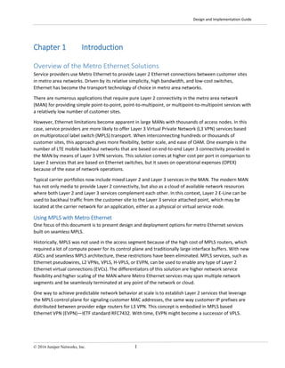
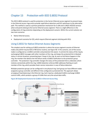
Establishing End-to-End EVCs
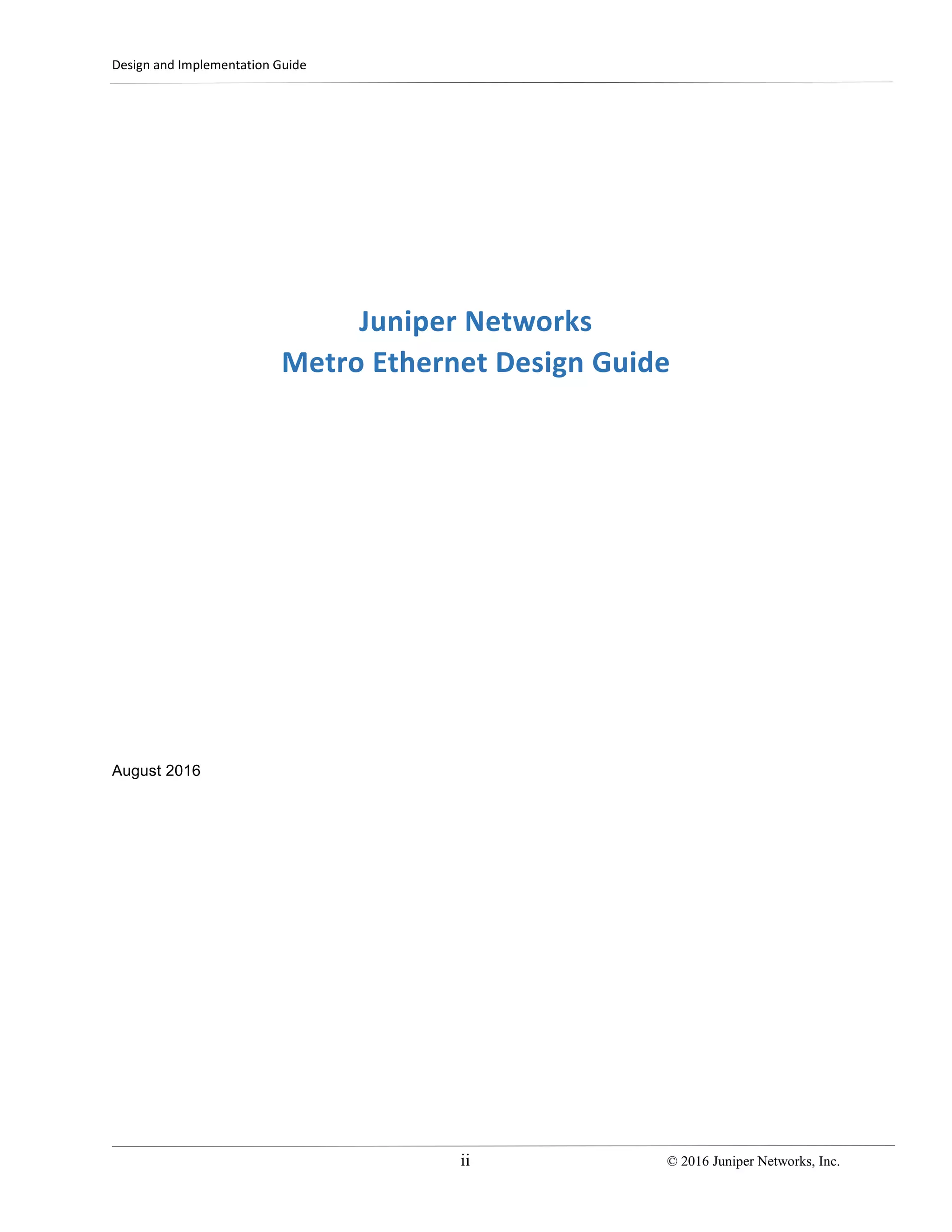
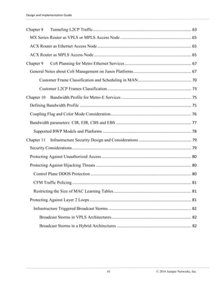
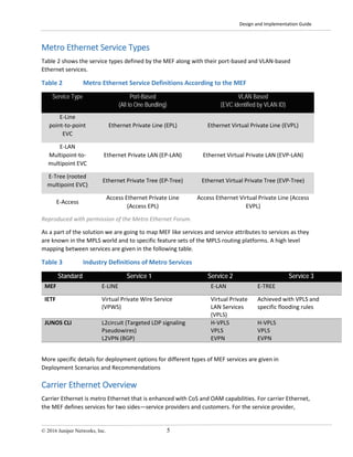
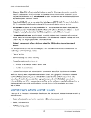
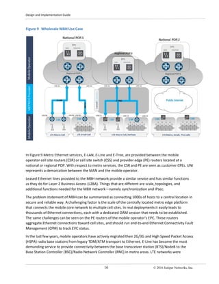
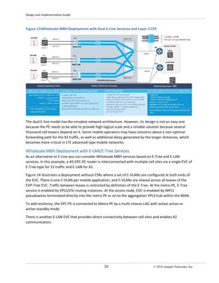
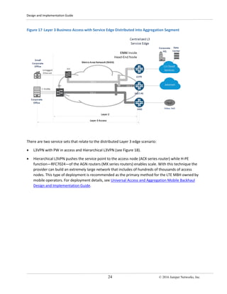
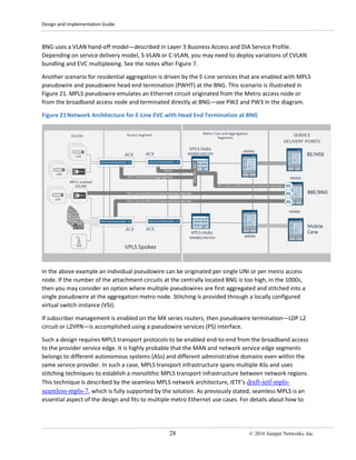
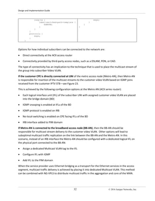
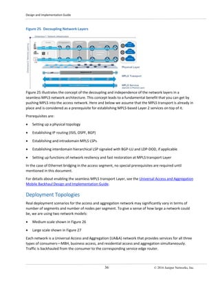
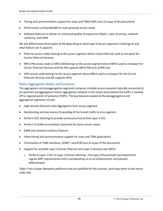
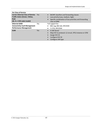
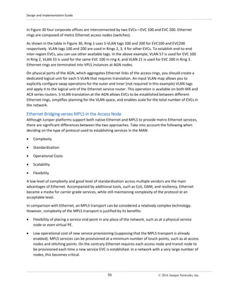
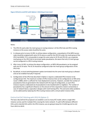
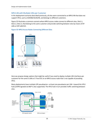
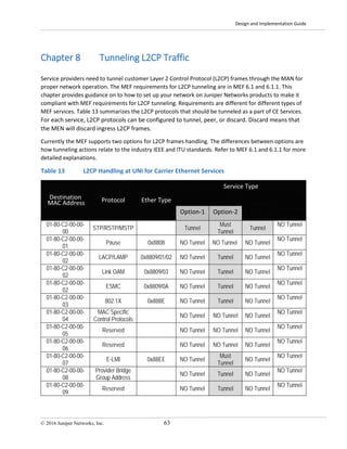
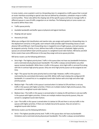
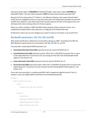
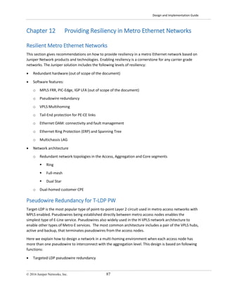
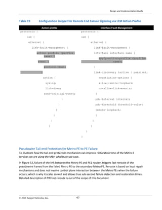
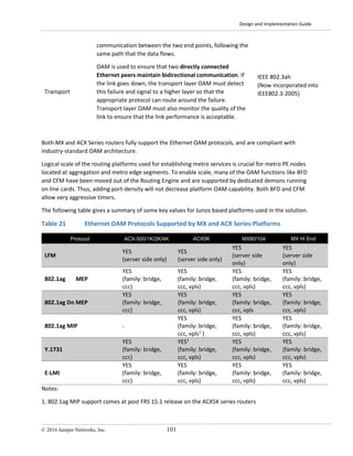
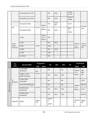
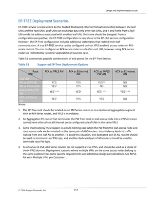
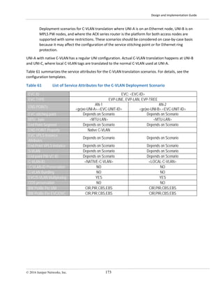
Figure 29 illustrates the end-to-end EVC established in the MAN between UNI-A1/A2 belonging to the
Ethernet access node and UNI-B belonging to MPLS AN on the right.
Figure 29 Layer 2 BA Reference Architecture
Table 10 proposes a template for the EVC structure, and summarizes the main attributes that should be
configured for an EVC to be enabled in the network. In addition to the regular components we have
defined two AN routers that act as stitching points of the EVC. AN1 terminates the Ethernet ring on the
left and AN2 pseudowire on the right. An end-to-end CFM session assures and controls EVC status.
Table 10 UNI and EVC Attributes
END POINTs
End Point
AN1
EVC Stitching
AGN
End Point
AN2
END POINT TYPE1 Ethernet Bridging VPLS MPLS
UNI / NNI /ENNI Attributes
UNI / NNI (If applicable) [ge|xe-<*>] unit <*> [ge|xe-<*>] unit <*> [ge|xe-<*>] unit <*>
MTU , byte
<MTU-LAN>
<MTU-ETH>
<MTU-LAN>
<MTU-ETH>
<MTU-LAN>
<MTU-ETH>
C-VLAN-ID <C-VLANs> - <C-VLANs>
C-VLAN Bundling3 YES/NO - YES/NO
BW Profile Per UNI CIR,PIR,CBS,EBS - CIR,PIR,CBS,EBS
EVC Multiplexing4 YES/NO - YES/NO
EVC Attributes and Services
EVC ID Unique circuit ID for the end-to-end circuit in the network; can be used by ELMI
EVC TYPE
EP-LINE / EP-LAN / EP-TREE / EP-ACCESS
EVP-LINE / EVP-LAN / EVP-TREE / EVP-ACCESS
EVC VPLS Instance - <VPLS-ID> -
S-VLAN tag2 <S-VLAN> <S-VLAN> <S-VLAN>
End point PW VC-ID - <VC-ID> <VC-ID>
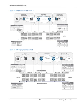
C-VLAN-ID Preservation YES/NO YES/NO
COS preservation YES/NO YES/NO
BW Profile Per EVC/OVC CIR,PIR,CBS,EBS CIR,PIR,CBS,EBS](https://image.slidesharecdn.com/metro-ethernet-dg-170624133948/85/Metro-ethernet-dg-56-320.jpg)


![Design and Implementation Guide
© 2016 Juniper Networks, Inc. 83
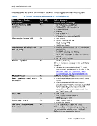
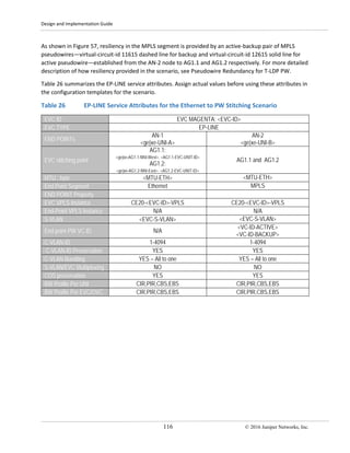
confined to its own CPE domain. This would correspond to Metro Ethernet EVC with enabled option for
L2CP protocols tunneling (see Tunneling L2CP Traffic).
• BGP based site-id: Both BGP VPLS and [PBB-]EVPN use a similar mechanism to prevent loops while
enabling CE dual homing (either active-standby or active-active). In both cases, the fact that the
same NLRI is learned from different BGP neighbors but with some different attributes (same site-id
with different priority on the BGP VPLS, or same MAC address, same Ethernet Segment Identifier
with designated forwarded decision).
• Dual Homed CPE with MC-LAG: On MX Series routers multichassis link aggregation (MC-LAG)
enables a device to form a logical LAG interface with two or more other devices. MC-LAG provides
benefits over a traditional LAG in terms of node level redundancy, multi-homing support, and loop-
free Layer 2 network without running Spanning Tree Protocol (STP) or G.8032. These benefits make
this method useful when interconnecting Juniper-based MAN with third party CPEs. MC-LAG can be
configured for the VPLS routing instance (see Protecting Dual-homed CPE with MC-LAG), CCC
application, and Layer 2 circuit encapsulation types.
• LDP based VPLS does not have a built-in mechanism to prevent customer triggered broadcast storms
when it comes to dual-homed CPEs. It is necessary to rely on the CPE running some flavor of
Spanning Tree, and its BPDUs being appropriately tunneled through the VPLS instance. It is all very
manual and still relies on the basic capabilities of Spanning Tree. We recommend that you deploy
this option with active-backup MC-LAG with LACP for state propagation (see Protecting Dual-homed
CPE with MC-LAG).
• Newer architectures, such as EVPN, or PBB-EVPN, have introduced mechanisms to enable all-active
multi-homed customer connections, without causing a broadcast storm. The architecture principle is
not new, but is inherited from legacy technologies, such as ATM LAN Emulation. Essentially,
different topologies are built for BUM traffic and known unicast traffic. Known unicast cannot
produce, by its nature, a broadcast storm because it never gets replicated. The traffic that causes a
broadcast storm (when there is a looped topology) is the BUM. Using BGP signaling with both EVPN
and PBB-EVPN creates a loop-free BUM topology, while the unicast topology has all links active,
which means it has loops, but those loops will never affect the BUM traffic.
There are cases where customers may have unexpected backdoor links between CEs. Those situations
cannot be handled by the mechanisms described above, and will result in customer-triggered broadcast
storms.](https://image.slidesharecdn.com/metro-ethernet-dg-170624133948/85/Metro-ethernet-dg-92-320.jpg)


![Design and Implementation Guide
118 © 2016 Juniper Networks, Inc.
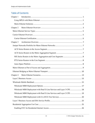
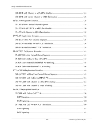
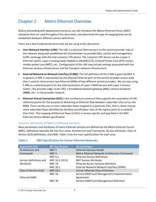
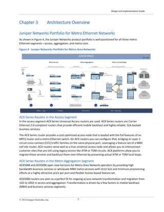
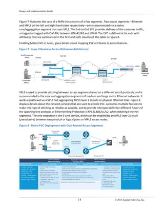
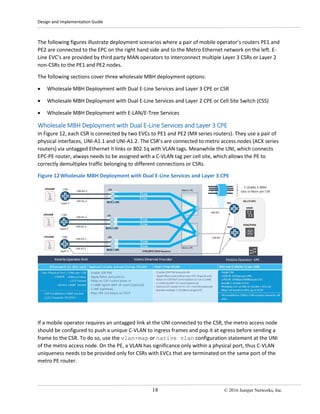
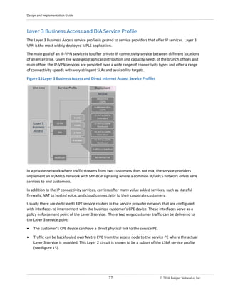
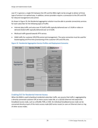
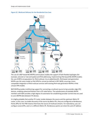
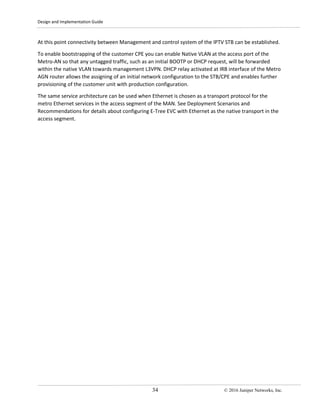
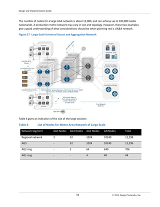
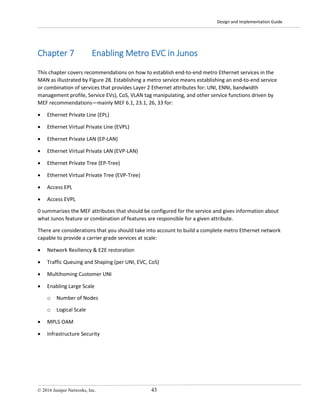
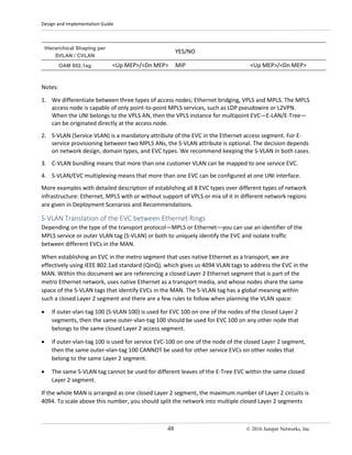
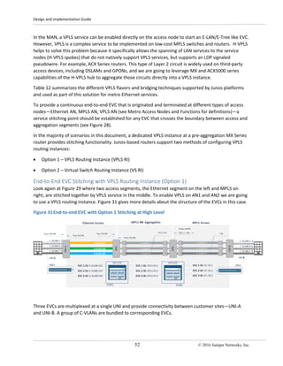
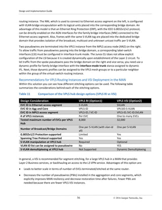
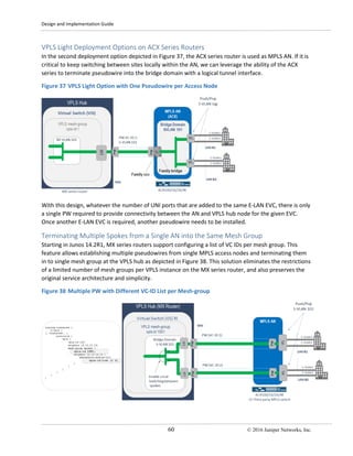
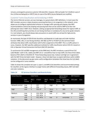
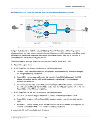
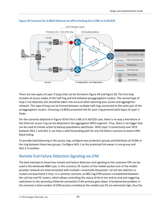
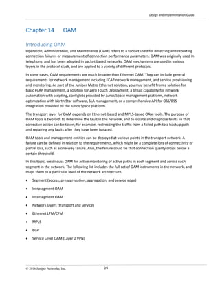
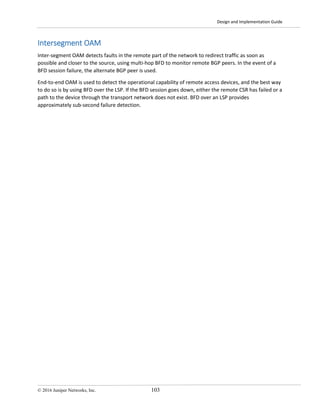
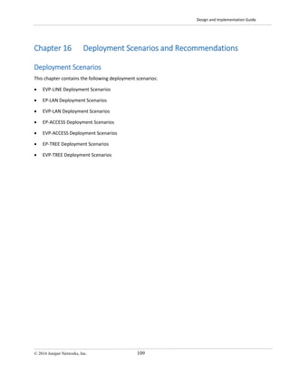
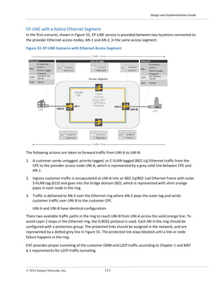
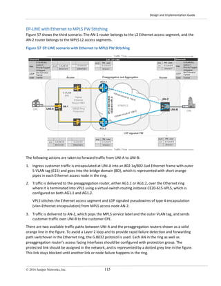
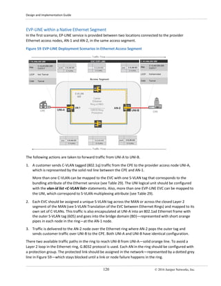
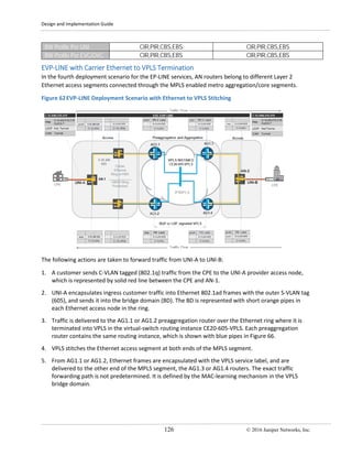
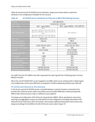
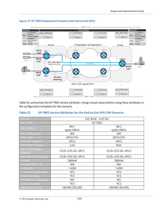
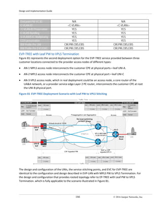
5. Traffic is delivered over the Ethernet access ring to the AN-2 node, which pops the outer S-VLAN tag
and sends traffic to the customer CPE.
There are two available traffic paths in each Ethernet access segment to the preaggregation routers
shown with a solid orange line in Figure 58. To avoid Layer 2 loops and to provide rapid failure detection
and forwarding path switchover in the Ethernet ring, the G.8032 protocol is used. Each AN in the ring as
well as preaggregation router’s access facing interfaces should be configured with a protection group.
The protected links should be assigned in the network, and are represented by a dotted grey line in
Figure 58. The protected link stays blocked until a link or node failure happens in the ring.
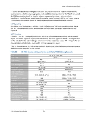
The following table summarizes the EP-LINE service attributes. Assign actual values before using these
attributes in the configuration templates for the scenario.
Table 27 EP-LINE Service Attributes for the Ethernet-to-VPLS Stitching Scenario
EVC ID EVC MAGENTA
EVC TYPE EP-LINE: <EVC-ID>
END POINTs
<AN-1-ID>
<ge|xe-UNI-A>
<AN-2-ID>
[ge|xe-<AUNI-B>]
EVC Stitching point
AG1.1:
<ge|xe-AG1.1-NNI-West>. <AG1.1-EVC-UNIT-ID>
AG1.2:
<ge|xe-AG1.2-NNI-East>. <AG1.2-EVC-UNIT-ID>
AG2.1:
<ge|xe-AG2.1-NNI-West>. <AG2.1-EVC-UNIT-ID>
AG2.2:
<ge|xe-AG2.2-NNI-East>. <AG2.2-EVC-UNIT-ID>
MTU , byte <MTU-ETH> <MTU-ETH>
End Point Segment Ethernet Ethernet
END POINT Property
EVC VPLS Instance CE20-<EVC-ID>-VPLS CE20-<EVC-ID>-VPLS
End-Point VPLS Instance N/A N/A
S-VLAN <EVC-S-VLAN> <EVC-S-VLAN>
End point PW VC ID N/A N/A
C-VLAN-ID 1-4094 1-4094
C-VLAN-ID Preservation YES YES
C-VLAN Bundling YES - All in one YES – All in one
S-VLAN/EVC Multiplexing No No
COS preservation YES YES
BW Profile Per UNI CIR,PIR,CBS,EBS CIR,PIR,CBS,EBS
BW Profile Per EVC/OVC CIR,PIR,CBS,EBS CIR,PIR,CBS,EBS](https://image.slidesharecdn.com/metro-ethernet-dg-170624133948/85/Metro-ethernet-dg-127-320.jpg)
![Design and Implementation Guide
© 2016 Juniper Networks, Inc. 121
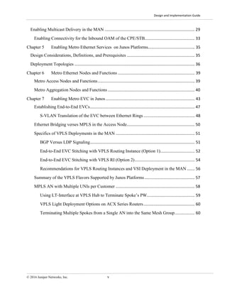
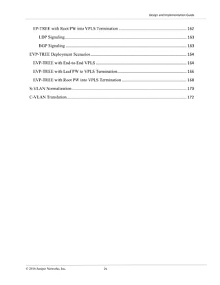
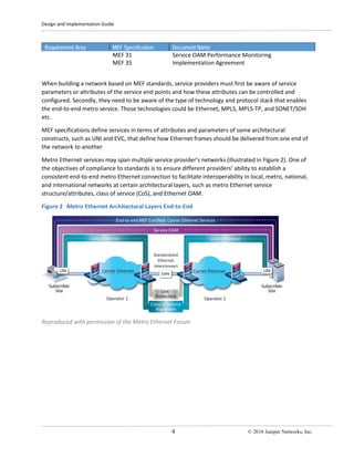
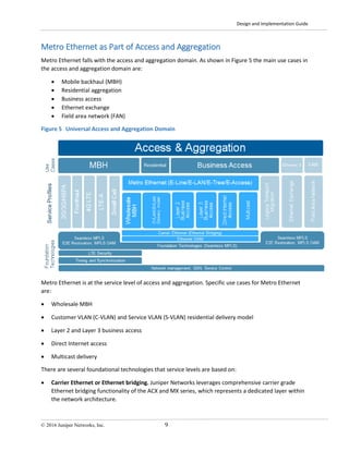
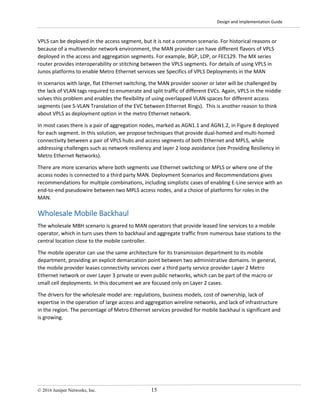
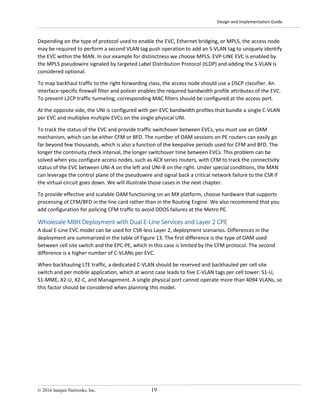
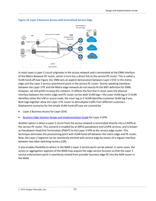
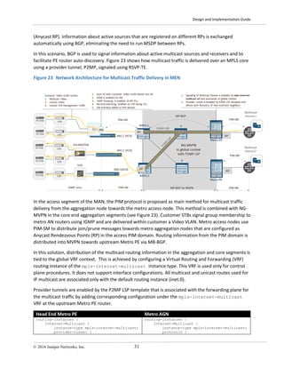
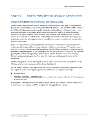
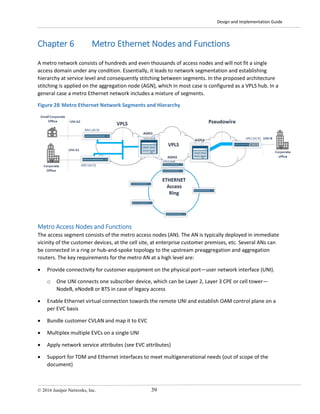
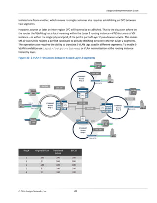
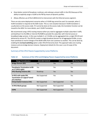
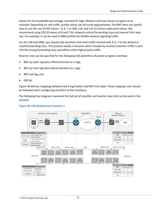
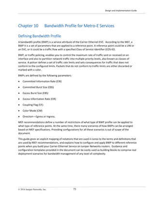
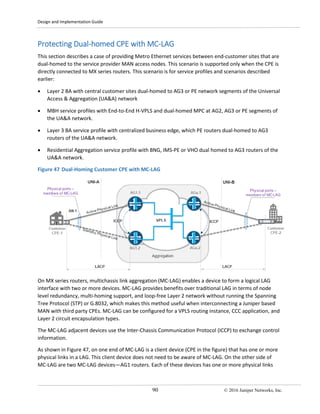
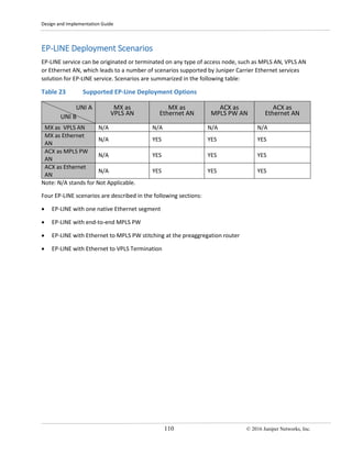
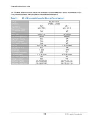
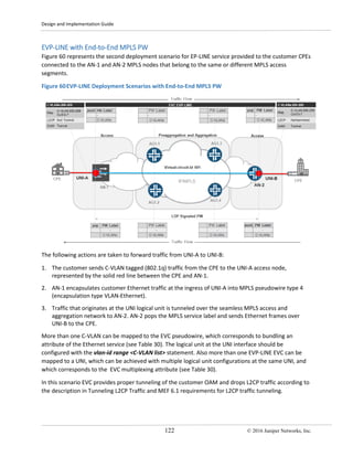
EVC provides proper tunneling of the customer OAM traffic and drops any L2CP according to the
description in Tunneling L2CP Traffic and MEF 6.1 requirements for L2CP traffic tunneling.
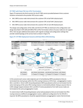
The following table summarizes the EVP-LINE service attributes. Assign actual values before using these
attributes in the configuration templates for the scenario.
Table 29 EVP-LINE Service Attributes for Ethernet Access Segment
EVC ID EVC YELLOW:<EVC-ID>
EVC TYPE EVP-LINE
END POINTs
AN-1
[ge|xe-<UNI-A>] . <EVC-UNIT-ID>
AN-2
[ge|xe-<UNI-B>] . <EVC-UNIT-ID>
EVC stitching point N/A N/A
UNI MTU , byte <MTU-LAN> <MTU-LAN>
End Point Segment Ethernet Ethernet
END POINT Property
EVC VPLS Instance N/A N/A
End-Point VPLS Instance N/A N/A
S-VLAN <EVC-S-VLAN> <EVC-S-VLAN>
End point PW VC ID N/A N/A
C-VLAN-ID <C-VLANs> <C-VLANs>
C-VLAN-ID Preservation YES YES
C-VLAN Bundling YES YES
S-VLAN/EVC Multiplexing YES YES
COS preservation YES YES
BW Profile Per UNI CIR,PIR,CBS,EBS CIR,PIR,CBS,EBS
BW Profile Per EVC/OVC CIR,PIR,CBS,EBS CIR,PIR,CBS,EBS](https://image.slidesharecdn.com/metro-ethernet-dg-170624133948/85/Metro-ethernet-dg-130-320.jpg)
![Design and Implementation Guide
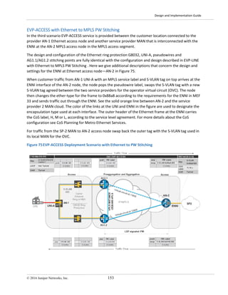
© 2016 Juniper Networks, Inc. 125
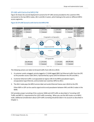
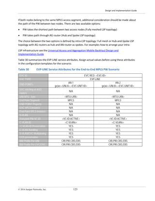
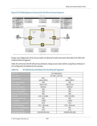
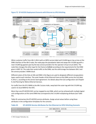
2 MPLS access node should be configured with the vlan-id-range <C-VLAN list> statement. More than
one EVP-LINE EVC can be mapped to a UNI, which can be achieved with multiple logical unit
configurations at the same UNI that corresponds to the EVC multiplexing attribute (see Table 31). At the
stitching point of AG1.1 and AG1.2, multiple EVCs that belong to the same customer are mapped into
the same VS routing instance with multiple bridge domains (see Figure 32, for example), or one bridge
domain per S-VLAN.
There are two traffic paths from UNI-A to the preaggregation routers, shown by a solid orange line in
Figure 61. To avoid Layer 2 loops and to provide rapid failure detection and forwarding path switchover
in the Ethernet ring, the G.8032 protocol is used. Each AN in the ring, as well as preaggregation router’s
access facing interfaces, should be configured with a protection group. The protected link should be
assigned in the network, and is represented by dotted grey line in Figure 61, which stays blocked until
another link or node failure happens in the ring. For a description and configuration template for the
G.8032 protocol in the Ethernet ring see Tunneling L2CP Traffic.
To provide resiliency in the MPLS segment an active-backup pair of MPLS pseudowires—virtual-circuit-id
11605 dashed blue line for backup and virtual-circuit-id 12605 solid blue line for active pseudowire in
the Figure 61—are established from AN-2 node to AG1.1 and AG1.2 respectively. For a detailed
description of how resiliency is provided, see Pseudowire Redundancy for T-LDP PW.
EVC provides proper tunneling of the customer OAM traffic and drops L2CP traffic according to the
description in Tunneling L2CP Traffic and MEF 6.1 requirements for L2CP traffic tunneling.
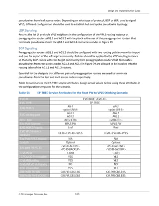
Table 31 summarizes the EVP-LINE service attributes. Assign actual values before using these attributes
in the configuration templates for the scenario.
Table 31 EVP-LINE Service Attributes for the Ethernet to PW Stitching Scenario
EVC ID EVC YELLOW: <EVC-ID>
EVC TYPE EVP-LINE
END POINTs
AN-1
[ge|xe-<UNI-A>] . <EVC-UNIT-ID>
AN-2
[ge|xe-<UNI-B>] . <EVC-UNIT-ID>
EVC stitching at AGG
routers
AG1.1:
<ge|xe-AG1.1-NNI-West>. <AG1.1-EVC-UNIT-ID>
AG1.2:
<ge|xe-AG1.2-NNI-East>. <AG1.2-EVC-UNIT-ID>
AG1.1
AG1.2
UNI MTU , byte <MTU-LAN> <MTU-LAN>
End Point Segment Ethernet MPLS
END POINT Property
EVC VPLS Instance CE20-605-VPLS CE20-605-VPLS
End-Point VPLS Instance N/A N/A
S-VLAN <EVC-S-VLAN> <EVC-S-VLAN>
End point PW VC ID N/A
<VC-ID-ACTIVE>
<VC-ID-BACKUP>
C-VLAN-ID <C-VLANs> <C-VLANs>
C-VLAN-ID Preservation YES YES
C-VLAN Bundling YES YES
COS preservation YES YES](https://image.slidesharecdn.com/metro-ethernet-dg-170624133948/85/Metro-ethernet-dg-134-320.jpg)
![Design and Implementation Guide
© 2016 Juniper Networks, Inc. 127
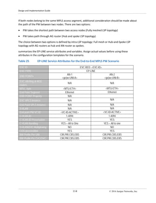
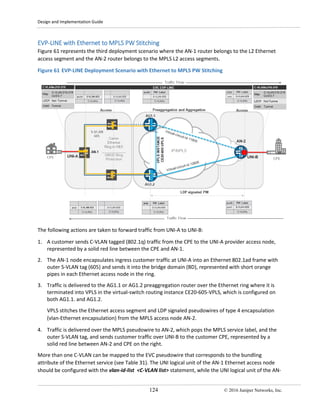
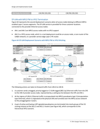
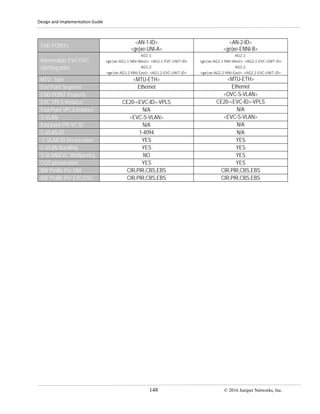
6. AG1.3 or AG1.4 router pops the MPLS service label and sends the traffic into Ethernet access
segment on the right with the same outer S-VLAN tag (605) as the original in the AN-1 node access
segment.
7. Traffic is delivered over Ethernet access ring to the AN-2 node, which pops the outer S-VLAN tag and
sends customer C-VLAN tagged traffic to the customer CPE.
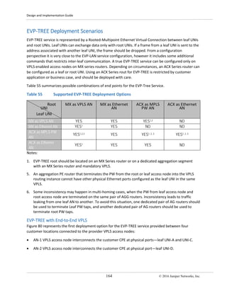
Table 32 summarizes the EVP-LINE service attributes. Assign actual values before using these attributes
in the configuration templates for the scenario.
Table 32 EVP-LINE Service Attributes for the Ethernet to VPLS Stitching Scenario
EVC ID EVC YELLOW: <EVC-ID>
EVC TYPE EVP-LINE
END POINTs
AN-1
[ge|xe-<UNI-A>] . <EVC-UNIT-ID>
AN-2
[ge|xe-<UNI-B>] . <EVC-UNIT-ID>
EVC stitching point
AG1.1:
<ge|xe-AG1.1-NNI-West>. <AG1.1-EVC-UNIT-ID>
AG1.2:
<ge|xe-AG1.2-NNI-East>. <AG1.2-EVC-UNIT-ID>
AG2.1:
<ge|xe-AG2.1-NNI-West>. <AG2.1-EVC-UNIT-ID>
AG2.2:
<ge|xe-AG2.2-NNI-East>. <AG2.2-EVC-UNIT-ID>
UNI MTU , byte <MTU-LAN> <MTU-LAN>
End Point Segment Ethernet Ethernet
END POINT Property
EVC VPLS Instance N/A N/A
End-Point VPLS Instance N/A N/A
S-VLAN <EVC-S-VLAN> <EVC-S-VLAN>
End point PW VC ID N/A N/A
C-VLAN-ID <C-VLANs> <C-VLANs>
C-VLAN-ID Preservation YES YES
C-VLAN Bundling YES YES
EVC/S-VLAN Multiplexing YES YES
COS preservation YES YES
BW Profile Per UNI CIR,PIR,CBS,EBS CIR,PIR,CBS,EBS
BW Profile Per EVC/OVC CIR,PIR,CBS,EBS CIR,PIR,CBS,EBS
More than one C-VLAN can be mapped to the EVC pseudowire, which corresponds to the bundling
attribute of the Ethernet service (see Table 32). The UNI logical unit of the Ethernet access nodes on AN-
1 and AN-2 should be configured with the vlan-id-list <C-VLAN list> statement. Also more than one
EVP-LINE EVC can be mapped to a UNI, which can be achieved with multiple logical unit configurations
at the same UNI, and corresponds to EVC multiplexing attribute (see Table 32). At the AG1.1 and AG1.2
stitching points multiple EVCs/S-VLANs that belong to the same customer are mapped into the same VS
routing instance with multiple bridge domains (see Figure 32 for example)—one bridge domain per S-
VLAN.
There are two available paths in each Ethernet access segment from the access node to the
preaggregation routers as shown by a solid orange line in Figure 62. To avoid Layer 2 loops and provide
rapid failure detection and forwarding path switchover in the Ethernet ring, the G.8032 protocol is used.](https://image.slidesharecdn.com/metro-ethernet-dg-170624133948/85/Metro-ethernet-dg-136-320.jpg)
![Design and Implementation Guide
© 2016 Juniper Networks, Inc. 135
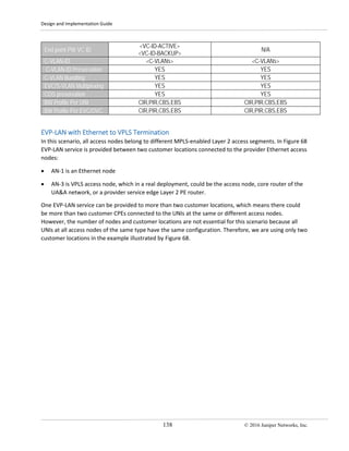
EVP-LAN within Pure Ethernet Segment
In the first scenario EVP-LAN service is provided between two customer locations connected to the
provider Ethernet access nodes AN-1 and AN-2 in the same access segment.
Figure 66 EVP-LAN Deployment Scenario for the Ethernet Access Segment
One EVP-LAN service can be provided to more than two customer locations, which means there can be
more than two customer locations connected to different UNIs at the Ethernet access nodes.
However, the number of nodes and customer locations are not essential for this deployment scenario
because all UNIs at all access nodes have the same configuration. Therefore, we are using only two
customer locations in the example illustrated by Figure 66.
Design and configuration of the access nodes are the same as those described in EVP-LINE within a
Native Ethernet Segment.
Table 38 summarizes the EVP-LAN service attributes. Assign actual values before using these attributes
in the configuration templates for the scenario.
Table 38 EVP-LAN Service Attributes for the Ethernet Access Segment
EVC ID EVC YELLOW: <EVC-ID>
EVC TYPE EVP-LAN
END POINTs
AN-1
[ge|xe-<UNI-A>]. <EVC-UNIT-ID>
AN-2
[ge|xe-<UNI-B>] . <EVC-UNIT-ID>
EVC stitching at AGG
routers
N/A N/A
UNI MTU , byte <MTU-LAN> <MTU-LAN>
End Point Segment Ethernet Ethernet
END POINT Property
EVC VPLS Instance N/A N/A](https://image.slidesharecdn.com/metro-ethernet-dg-170624133948/85/Metro-ethernet-dg-144-320.jpg)
![Design and Implementation Guide
© 2016 Juniper Networks, Inc. 137
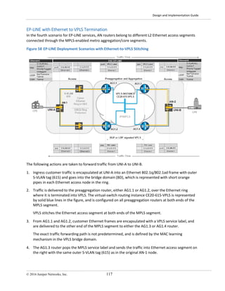
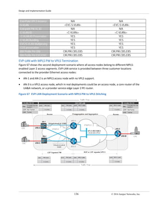
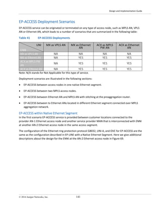
The following actions are taken to forward traffic from UNI-A to UNI-B:
1. A customer sends C-VLAN tagged (802.1q) Ethernet traffic from the CPE to provider access node
UNI-A, which is represented by a red solid line between the CPE and AN-1.
2. Customer Ethernet traffic is encapsulated at ingress UNI-A into MPLS pseudowire type 4,
encapsulation type vlan-Ethernet, which originates at the UNI logical unit and tunneled over the
MPLS access network to the preaggregation routers.
3. A pair of active and backup LDP-signaled pseudowires is terminated into mesh-groups of the VS
routing instance at the AG1.2 and AG1.1 routers, which corresponds to the hierarchical VPLS
scenario. A redundant pair of pseudowires provides network resiliency against preaggregation
router failure scenarios (see Pseudowire Redundancy for T-LDP PW for details). Preaggregation
routers and access node AN-3 are configured with BGP-signaled VPLS.
4. Traffic from the AG1.1 or AG1.2 stitching points is delivered to the AN-3 node, which pops MPLS
service label and sends customer traffic to the customer CPE through UNI-B. Because UNI-A and
UNI-C at AN-1 and AN-2 respectively are mapped to the same EVP-LAN EVC, then the solution
should allow traffic forwarding between them at VPLS hub level. To achieve that, mesh-groups at
the AG1.1 and AG1.2 routers are configured with the local-switching statement, which allows traffic
switching between pseudowires terminated into the same mesh-group.
More than one C-VLAN can be mapped at the UNI access node to the EVC pseudowire, which
corresponds to the bundling attribute of the Ethernet service (see Table 39). The UNI logical unit of the
MPLS access node AN-1 and AN-2 and VPLS access node AN-3 should be configured with the vlan-id-
range <C-VLAN list> statement, see the configuration template for details. Also, more than one EVP-
LINE EVC can be mapped to the UNI. This can be achieved with multiple logical unit configurations at the
same UNI, which corresponds to the EVC multiplexing attribute. At the AG1.1 and AG1.2 stitching points
multiple EVCs that belong to the same customer are mapped into the same VS routing instance with
multiple bridge domains with one bridge domain per S-VLAN. see Figure 32 for an example.
In this scenario, the EVC provides proper tunneling of the customer OAM and drops L2CP traffic as
described in Tunneling L2CP Traffic and MEF 6.1 requirements for L2CP traffic tunneling.
Table 39 summarizes the EVP-LAN service attributes. Assign actual values before using these attributes
in the configuration templates for the scenario.
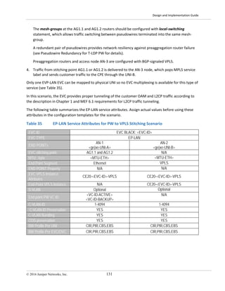
Table 39 EVP-LAN Service Attributes for the PW-to-VPLS Stitching Scenario
EVC ID EVC GREEN: <EVC-ID>
EVC TYPE EVP-LAN
END POINTs
AN-1
[ge|xe-<UNI-A>] . <EVC-UNIT-ID>
AN-2
[ge|xe-<UNI-B>]. <EVC-UNIT-ID>
EVC stitching point AG1.1 and AG1.2 N/A
UNI MTU , byte <MTU-LAN> <MTU-LAN>
End Point Segment MPLS PW MPLS VPLS
END POINT Property
EVC VPLS Instance CE20-<EVC-ID>-VPLS CE20-<EVC-ID>-VPLS
End-Point VPLS Instance N/A CE20-<EVC-ID>-VPLS
S-VLAN Optional Optional](https://image.slidesharecdn.com/metro-ethernet-dg-170624133948/85/Metro-ethernet-dg-146-320.jpg)
![Design and Implementation Guide
140 © 2016 Juniper Networks, Inc.
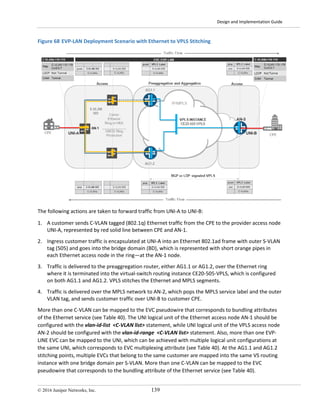
The UNI logical unit of the Ethernet access node on AN-1 should be configured with the vlan-id-list <C-
VLAN list> statement, while the UNI logical unit of the VPLS access node AN-2 should be configured with
vlan-id-range <C-VLAN list> statement. Also more than one EVP-LINE EVC can be mapped to a UNI,
which can be achieved with multiple logical unit configurations at the UNI that correspond to the EVC
multiplexing attribute (see Table 40). At the stitching points of AG1.1 and AG1.2 multiple EVCs that
belong to the same customer are mapped into the same VS routing instance with multiple bridge
domains, or one bridge domain per S-VLAN.
There two available traffic paths from UNI-A to the preaggregation routers, shown with the solid orange
line in Figure 68. To avoid Layer 2 loops and to provide rapid failure detection and forwarding path
switchover in the Ethernet ring, the G.8032 protocol is used. Each AN in the ring as well as the
preaggregation router’s access facing interfaces should be configured with a protection group.
Protected links should be assigned in the network, represented by dotted grey line in the diagram,
which stays blocked until other link or node failures happen in the ring.
Table 40 summarizes the EVP-LINE service attributes. Assign actual values before using these attributes
in the configuration templates for the scenario.
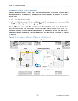
Table 40 EVP-LAN Service Attributes for Ethernet to VPLS Stitching Scenario
EVC ID EVC GREEN: <EVC-ID>
EVC TYPE EVP-LAN
END POINTs
AN-1
[ge|xe-<UNI-A>] . <EVC-UNIT-ID>
AN-2
[ge|xe-<UNI-B>]. <EVC-UNIT-ID>
EVC stitching point
AG1.1:
<ge|xe-AG1.1-NNI-West>. <AG1.1-EVC-UNIT-ID>
AG1.2:
<ge|xe-AG1.2-NNI-East>. <AG1.2-EVC-UNIT-ID>
AG2.1
AG2.2
UNI MTU , byte <MTU-LAN> <MTU-LAN>
End Point Segment Ethernet MPLS VPLS
END POINT Property N/A N/A
EVC VPLS Instance CE20-<EVC-ID>-VPLS CE20-<EVC-ID>-VPLS
End-Point VPLS Instance N/A CE20-<EVC-ID>-VPLS
S-VLAN <EVC-S-VLAN> <EVC-S-VLAN>
End point PW VC ID
<VC-ID-ACTIVE>
<VC-ID-BACKUP>
N/A
C-VLAN-ID <C-VLANs> <C-VLANs>
C-VLAN-ID Preservation YES YES
C-VLAN Bundling YES YES
EVC/S-VLAN Multiplexing YES YES
COS preservation YES YES
BW Profile Per UNI CIR,PIR,CBS,EBS CIR,PIR,CBS,EBS
BW Profile Per EVC/OVC CIR,PIR,CBS,EBS CIR,PIR,CBS,EBS](https://image.slidesharecdn.com/metro-ethernet-dg-170624133948/85/Metro-ethernet-dg-149-320.jpg)
![Design and Implementation Guide
150 © 2016 Juniper Networks, Inc.
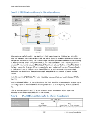
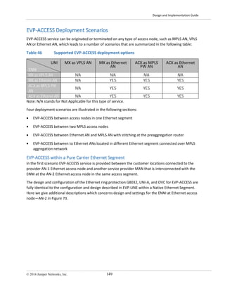
Figure 73 EVP-ACCESS Deployment Scenario for the Ethernet Segment
When customer traffic from AN-1 UNI-A with an S-VLAN tag on top arrives at the ENNI interface of the
AN-2 node, the node swaps the S-VLAN tag with a new S-VLAN tag agreed between the two service
providers for an operator virtual circuit (OVC). The node also changes the ether-type for the frame to
0x88a8 according to the requirements for the ENNI in MEF 33, and sends traffic through the ENNI—see
the solid orange line between AN-2 and service provider 2 MAN cloud. The different color links at the
UNI and ENNI in the figure are used to designate the encapsulation types used at each interface. The
outer header of the Ethernet frame at the ENNI carries the CoS label, H, M or L, according to the service
level agreement. For more details about CoS configuration see CoS Planning for Metro Ethernet
Services.
For the traffic from SP-2 MAN to the AN-2 node, the outer tag is swapped back with the S-VLAN tag used
in its local MAN for the OVC.
More than one EVP-ACCESS OVC can be mapped to one ENNI, which can be achieved with multiple
logical unit configurations at the same ENNI, which correspond to S-VLAN multiplexing attribute (see
Table 47).
Table 47 summarizes the EVP-ACCESS service attributes. Assign actual values before using these
attributes in the configuration templates for the scenario.
Table 47 EVP-ACCESS Service Attributes for the Ethernet Access Segment
EVC ID OVC YELLOW: <EVC-ID>
EVC TYPE EVP-ACCESS
END POINTs
AN-1
[ge|xe-<UNI-A>] . <EVC-UNIT-ID>
AN-2
[ge|xe-<UNI-ENNI-B>] . <EVC-UNIT-ID>](https://image.slidesharecdn.com/metro-ethernet-dg-170624133948/85/Metro-ethernet-dg-159-320.jpg)
![Design and Implementation Guide
152 © 2016 Juniper Networks, Inc.
The following actions are taken to forward traffic from UNI-A to ENNI:
1. Customer C-VLAN tagged (802.1q) Ethernet traffic is set from the CPE to the UNI-A provider access
node, which is represented by solid red line between the CPE and AN-1.
2. The AN-1 node pushes an additional S-VLAN tag on top of the customer frame and encapsulates
frames at the ingress of UNI-A into MPLS pseudowire type 4, encapsulation type vlan-Ethernet, and
tunnels the frames over the seamless MPLS access and aggregation network to the AN-2.
3. AN-2 node pops the MPLS service label and swaps the S-VLAN tag with a new S-VLAN tag agreed
between the two service providers for the operator virtual circuit (OVC). The node also changes the
ether-type for the frame to 0x88a8 according to the requirements for the ENNI given in MEF 33. AN-
2 then sends traffic through the ENNI. See the solid orange line between AN-2 and the service
provider 2 MAN cloud.
The different color links at the UNI and ENNI in the figure are used to designate the encapsulation type
used at each interface.
The outer header of the Ethernet frame at the ENNI carries the CoS label, H, M or L, according to the
service level agreement. For more details about CoS configuration see CoS Planning for Metro Ethernet
Services.
More than one EP-ACCESS OVC can be mapped to one ENNI, which can be achieved with multiple logical
unit configurations at the same ENNI, which correspond to S-VLAN multiplexing attribute (see Table 48).
Table 48 summarizes the EVP-ACCESS service attributes. Assign actual values before using these
attributes in the configuration templates for the scenario.
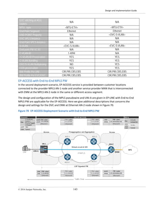
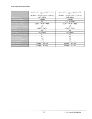
Table 48 EVP-ACCESS Service Attributes for the End-to-End MPLS PW Scenario
EVC ID OVC YELLOW: <EVC-ID>
EVC TYPE EVP-ACCESS
END POINTs
AN-1
[ge|xe-<UNI-A>] . <EVC-UNIT-ID>
AN-2
[ge|xe-<ENNI-B>] . <EVC-UNIT-ID>
EVC stitching point N/A N/A
UNI MTU , byte <MTU-LAN> <MTU-LAN>
End Point Segment MPLS MPLS
END POINT Property N/A <OVC-S-VLAN>
EVC VPLS Instance N/A N/A
End-Point VPLS Instance N/A N/A
S-VLAN N/A N/A
End point PW VC ID <VC-ID-ACTIVE> <VC-ID-ACTIVE>
C-VLAN-ID <C-VLANs> <C-VLANs>
C-VLAN-ID Preservation YES YES
C-VLAN Bundling YES YES
S-VLAN/EVC Multiplexing YES YES
COS preservation YES YES
BW Profile Per UNI CIR,PIR,CBS,EBS CIR,PIR,CBS,EBS
BW Profile Per EVC/OVC CIR,PIR,CBS,EBS CIR,PIR,CBS,EBS](https://image.slidesharecdn.com/metro-ethernet-dg-170624133948/85/Metro-ethernet-dg-161-320.jpg)
![Design and Implementation Guide
154 © 2016 Juniper Networks, Inc.
More than one EVP-ACCESS OVC can be mapped to one ENNI, which can be achieved with multiple
logical unit configurations at the same ENNI that correspond to the S-VLAN multiplexing attribute (see
Table 49).
Table 49 summarizes the EVP-ACCESS service attributes. Assign actual values before using these
attributes in the configuration templates for the scenario.
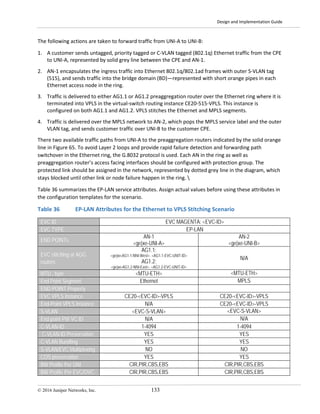
Table 49 EVP-ACCESS Service Attributes for the Ethernet to MPLS PW Stitching Scenario
EVC ID EVC YELLOW
EVC TYPE EP-LAN: <EVC-ID>
END POINTs
AN-1
[ge|xe-<UNI-A>]. <EVC-UNIT-ID>
AN-2
[ge|xe-<ENNI-B>] . <EVC-UNIT-ID>
EVC stitching at AGG
routers
AG1.1:
<ge|xe-AG1.1-NNI-West>. <AG1.1-EVC-UNIT-ID>
AG1.2:
<ge|xe-AG1.2-NNI-East>. <AG1.2-EVC-UNIT-ID>
AG2.1 and AG2.2
MTU , byte <MTU-ETH> <MTU-ETH>
End Point Segment Ethernet MPLS
END POINT Property <OVC-S-VLAN>
EVC VPLS Instance CE20-<EVC-ID>-VPLS CE20-<EVC-ID>-VPLS
End-Point VPLS Instance N/A
<VC-ID-ACTIVE>
<VC-ID-BACKUP>
S-VLAN <EVC-S-VLAN> <EVC-S-VLAN>
End point PW VC ID N/A N/A
C-VLAN-ID <C-VLANs> <C-VLANs>
C-VLAN-ID Preservation YES YES
C-VLAN Bundling YES YES
S-VLAN/EVC Multiplexing YES YES
COS preservation YES YES
BW Profile Per UNI CIR,PIR,CBS,EBS CIR,PIR,CBS,EBS
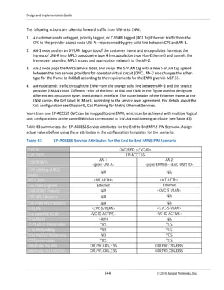
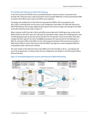
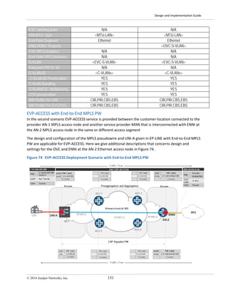
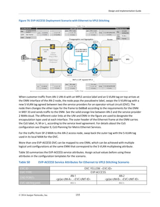
EVP-ACCESS with Ethernet to VPLS Stitching
In the fourth scenario EVP-ACCESS service provided between the customer location connected to the
provider AN-1 Ethernet access node and another service provider MAN that is interconnected with the
ENNI at the AN-2 Ethernet access node in a different access segment.
The design and configuration of the Ethernet ring protection G8032, UNI-A, pseudowires, and service
stitching at preaggregation routers are identical to the configuration and design described in EVP-LINE
with Carrier Ethernet to VPLS Termination . Here we give additional descriptions that concerns the
design and settings for the ENNI at Ethernet access node—AN-2 in Figure 76.](https://image.slidesharecdn.com/metro-ethernet-dg-170624133948/85/Metro-ethernet-dg-163-320.jpg)
![Design and Implementation Guide
© 2016 Juniper Networks, Inc. 165
• AN-3 VPLS access node, which in real deployment could be either an access node, a core router of
the UA&A network, or a provider service edge Layer 2 PE router, interconnects the customer CPE at
the root UNI-B physical port.
The design and configuration of the UNIs and EVC for EVP-TREE are fully identical to the configuration
and design described in EVP-LAN with MPLS PW to VPLS Termination where all access nodes support
VPLS. No additional service stitching is required. For the design and configuration that provides rooted
topology refer to EP-TREE with End-to-End VPLS, which is fully applicable to the scenario in Figure 80.
Figure 80 EVP-TREE Deployment Scenario with End-to-End VPLS
Table 56 summarizes the EVP-TREE service attributes. Assign actual values before using these attributes
in the configuration templates for the scenario.
Table 56 EVP-TREE Service Attributes for PW to VPLS Stitching Scenario
EVC ID EVC BLUE: <EVC-ID>
EVC TYPE EVP-TREE
END POINTs
AN-1
[ge|xe-<UNI-A>] . <EVC-UNIT-ID>
AN-2
[ge|xe-<UNI-B>]. <EVC-UNIT-ID>
EVC stitching point N/A N/A
UNI MTU , byte <MTU-LAN> <MTU-LAN>
End Point Segment MPLS VPLS MPLS VPLS
END POINT Property Leaf Root
EVC VPLS Instance CE20-<EVC-ID>-VPLS CE20-<EVC-ID>-VPLS
End-Point VPLS Instance CE20-<EVC-ID>-VPLS CE20-<EVC-ID>-VPLS
S-VLAN Optional Optional](https://image.slidesharecdn.com/metro-ethernet-dg-170624133948/85/Metro-ethernet-dg-174-320.jpg)
![Design and Implementation Guide
© 2016 Juniper Networks, Inc. 167
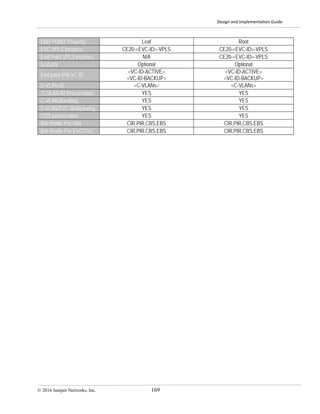
Table 57 summarizes the EVP-TREE service attributes. Assign actual values before using these attributes
in the configuration templates for the scenario.
Table 57 EVP-TREE Service Attributes for Leaf PW to VPLS Stitching Scenario
EVC ID EVC BLUE: <EVC-ID>
EVC TYPE EVP-TREE
END POINTs
AN-1
[ge|xe-<UNI-A>] . <EVC-UNIT-ID>
AN-2
[ge|xe-<UNI-B>]. <EVC-UNIT-ID>
EVC stitching point AG2.1 and AG2.2 N/A
UNI MTU , byte <MTU-LAN> <MTU-LAN>
End Point Segment MPLS PW MPLS VPLS
END POINT Property Leaf Root
EVC VPLS Instance CE20-<EVC-ID>-VPLS CE20-<EVC-ID>-VPLS
End-Point VPLS Instance N/A CE20-<EVC-ID>-VPLS
S-VLAN Optional Optional
End point PW VC ID
<VC-ID-ACTIVE>
<VC-ID-BACKUP>
N/A
C-VLAN-ID <C-VLANs> <C-VLANs>
C-VLAN-ID Preservation YES YES
C-VLAN Bundling YES YES
S-VLAN/EVC Multiplexing YES YES
COS preservation YES YES
BW Profile Per UNI CIR,PIR,CBS,EBS CIR,PIR,CBS,EBS
BW Profile Per EVC/OVC CIR,PIR,CBS,EBS CIR,PIR,CBS,EBS](https://image.slidesharecdn.com/metro-ethernet-dg-170624133948/85/Metro-ethernet-dg-176-320.jpg)
![Design and Implementation Guide
168 © 2016 Juniper Networks, Inc.
EVP-TREE with Root PW into VPLS Termination
Figure 82 represents the third deployment scenario for the EP-TREE service provided between three
customer locations connected to the provider VPLS access nodes:
• AN-1 MPLS access node interconnects the customer CPE at physical ports—leaf UNI-A.
• AN-2 MPLS access node interconnects the customer CPE at physical port—leaf UNI-C
• AN-3 MPLS access node interconnects the customer CPE at physical port—root UNI-B.
Figure 82 EVP-TREE Deployment Scenario with Root and Leaf PWs to VPLS Stitching
The design and configuration of the UNIs, service stitching points and EVC for EVP-TREE are identical to
the configuration and design described in EVP-LAN with MPLS PW to VPLS Termination where all access
nodes do not support VPLS. For the design and configuration that provides rooted topology, refer to EP-
TREE with Root PW into VPLS Termination, which is applicable to the scenario in Figure 82.
Table 58 summarizes the EVP-TREE service attributes. Assign actual values before using these attributes
in the configuration templates for the scenario.
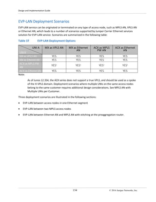
Table 58 EP-TREE Service Attributes for Root PW to VPLS Stitching Scenario
EVC ID EVC BLUE: <EVC-ID>
EVC TYPE EVP-TREE
END POINTs
AN-1
[ge|xe-<UNI-A>] . <EVC-UNIT-ID>
AN-2
[ge|xe-<UNI-B>]. <EVC-UNIT-ID>
EVC stitching point AG1.1 and AG1.2 AG2.1 and AG2.2
UNI MTU , byte <MTU-LAN> <MTU-LAN>
End Point Segment MPLS PW MPLS VPLS](https://image.slidesharecdn.com/metro-ethernet-dg-170624133948/85/Metro-ethernet-dg-177-320.jpg)
![Design and Implementation Guide
170 © 2016 Juniper Networks, Inc.
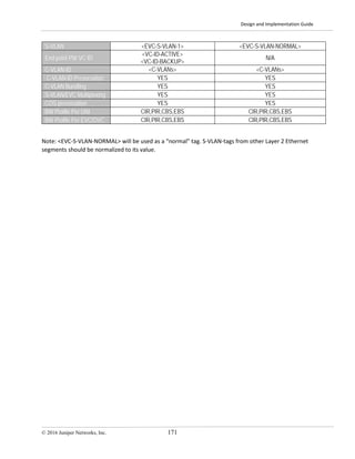
S-VLAN Normalization
When the EVC for the E-Service spans multiple closed Layer 2 carrier Ethernet segments that are
separated by MPLS-enabled metro aggregations and core segments, you may not be able to use the
same S-VLAN tag in different segments to map it to the end-to-end EVC (see Figure 83).
Figure 83 S-VLAN Normalization Scenario
In this case a dedicated S-VLAN-tag can be chosen for the EVC. To provide L2 connectivity between the
UNIs, S-VLAN normalization should be deployed. The Carrier Ethernet to VPLS stitching point is the point
where S-VLAN normalization function logically falls. For multipoint-to-multipoint services such as E-LAN,
more than one S-VLAN normalization point may need to be provisioned.
Table 59 summarizes the service attributes for the EVP-LAN that requires S-VLAN normalization.
Table 59 Service attributes for EVC with S-VLAN Normalization
EVC ID EVC GREEN: <EVC-ID>
EVC TYPE EVP-LAN
END POINTs
AN-1
[ge|xe-<UNI-A>] . <EVC-UNIT-ID>
AN-2
[ge|xe-<UNI-B>]. <EVC-UNIT-ID>
EVC stitching point
AG1.1:
<ge|xe-AG1.1-NNI-West>. <AG1.1-EVC-UNIT-ID>
AG1.2:
<ge|xe-AG1.2-NNI-East>. <AG1.2-EVC-UNIT-ID>
AG2.1:
<ge|xe-AG1.1-NNI-West>. <AG1.1-EVC-UNIT-ID>
AG2.2:
<ge|xe-AG1.2-NNI-East>. <AG1.2-EVC-UNIT-ID>
UNI MTU , byte <MTU-LAN> <MTU-LAN>
End Point Segment Ethernet MPLS VPLS
END POINT Property N/A N/A
EVC VPLS Instance CE20-<EVC-ID>-VPLS CE20-<EVC-ID>-VPLS
End-Point VPLS Instance N/A CE20-<EVC-ID>-VPLS](https://image.slidesharecdn.com/metro-ethernet-dg-170624133948/85/Metro-ethernet-dg-179-320.jpg)
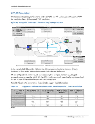

This document provides an overview of Metro Ethernet network solutions from Juniper Networks. It discusses key Metro Ethernet concepts like UNI, E-NNI, and EVCs. The document also reviews Metro Ethernet Forum specifications that define metro Ethernet services, architectures, service attributes, class of service, and OAM. These standards help service providers build compliant networks and control service endpoint attributes. The solutions presented leverage Juniper hardware and software to enable metro Ethernet services over Ethernet, MPLS, MPLS-TP and SONET/SDH technologies.


![Avaya ethernet switching portfolio presentation [level 3 - tdi][1]](https://cdn.slidesharecdn.com/ss_thumbnails/avayaethernetswitching-portfoliopresentationlevel3-tdi1-100608162808-phpapp01-thumbnail.jpg?width=640&height=640&fit=bounds)


