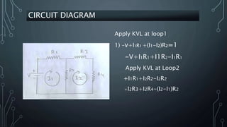
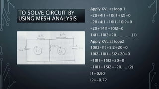
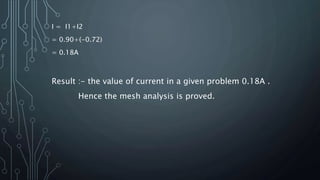
NAGPUR INSTITUTE OF TECHNOLOGY
Guided by:-
Miss.Pradyna Korde
NIT POLYTECHNIC
MICRO PROJECT OF ELECTRIC CIRCUITS &
NETWORK
POWER POINT
PRESENTATION
OF MESH
ANALYSIS
TITLE :- POWER POINT PRESENTATION OF MESH
ANALYSIS
PRESENTED BY
DARSHANA BENDE
DAMINI GARDE
DHANANJAY RAUT
MAHIMA GADRE
ASHISH SADAVARTI
MICRO PROJECT
CONTENT
• INTRODUCTION
• DEFINITION
• CIRCUIT DIAGRAM
• EXPLANATION
• TO SOLVE CIRCUIT BY USING MESH ANALYSIS
• RESULT
• CONCLUSION
INTRODUCTION
In 1845 , a german physists ,gustav Kirchhoff's
developed a pair of laws and energy within
electrical circuit . the rules are commonly known
as Kirchhoff's circuit laws
Other law deals with the
voltage around A closed circuit ,known as Kirchhoff's
voltage law (kvl).
KIRCHHOFF’S VOLTAGE LAW OR KVL
STATEMENT-
• “In any closed loop network the total voltage around the loop is
equal to the sum of the sum of all the voltage drop within the
same loop” which is also equal to zero.
• In other word the algebraic sum of all voltage within the loop
must be equal to zero.
• This idea by Kirchhoff's is known as the conversion of energy.
CIRCUIT DIAGRAM
Apply KVL at loop1
1) –v+I1R1 +(I1-I2)R2=1
-V+I1R1+I1R2-I1R1
Apply KVL at Loop2
+I1R1+I2R2-I2R2
+I2R3+I2R4-(I2-I1)R2
PROCEDURE
1. Identify the number of basic meshes .
2. Assign a current to each mesh.
3. Apply KVL around each loop to get an equation in terms of
the loop current.
4. Solve the resulting system of linear equation.
TO SOLVE CIRCUIT BY
USING MESH ANALYSIS
Apply KVL at loop 1
-20+4I1+10(I1+I2)=0
-20+4I1+10I1-10I2=0
-20+14I1-10I2=0
14I1-10I2=20………….(1)
Apply KVL at loop2
10(I2-I1)+5I2+20=0
10I2-10I1+5I2+20=0
-10I1+15I2+20=0
-10I1+15I2=-20……(2)
I1=0.90
I2=-0.72
I = I1+I2
= 0.90+(-0.72)
= 0.18A
Result :- the value of current in a given problem 0.18A .
Hence the mesh analysis is proved.
Thus we concluded that due to use of the mesh
analysis complex circuit convert into simple circuit
CONCLUSION
MESH ANALYSIS in Electric Circuits and Networks.pptx

MESH ANALYSIS in Electric Circuits and Networks.pptx

  • 1.
    NAGPUR INSTITUTE OFTECHNOLOGY Guided by:- Miss.Pradyna Korde NIT POLYTECHNIC MICRO PROJECT OF ELECTRIC CIRCUITS & NETWORK
  • 2.
  • 3.
    TITLE :- POWERPOINT PRESENTATION OF MESH ANALYSIS PRESENTED BY DARSHANA BENDE DAMINI GARDE DHANANJAY RAUT MAHIMA GADRE ASHISH SADAVARTI MICRO PROJECT
  • 4.
    CONTENT • INTRODUCTION • DEFINITION •CIRCUIT DIAGRAM • EXPLANATION • TO SOLVE CIRCUIT BY USING MESH ANALYSIS • RESULT • CONCLUSION
  • 5.
    INTRODUCTION In 1845 ,a german physists ,gustav Kirchhoff's developed a pair of laws and energy within electrical circuit . the rules are commonly known as Kirchhoff's circuit laws Other law deals with the voltage around A closed circuit ,known as Kirchhoff's voltage law (kvl).
  • 6.
    KIRCHHOFF’S VOLTAGE LAWOR KVL STATEMENT- • “In any closed loop network the total voltage around the loop is equal to the sum of the sum of all the voltage drop within the same loop” which is also equal to zero. • In other word the algebraic sum of all voltage within the loop must be equal to zero. • This idea by Kirchhoff's is known as the conversion of energy.
  • 7.
    CIRCUIT DIAGRAM Apply KVLat loop1 1) –v+I1R1 +(I1-I2)R2=1 -V+I1R1+I1R2-I1R1 Apply KVL at Loop2 +I1R1+I2R2-I2R2 +I2R3+I2R4-(I2-I1)R2
  • 8.
    PROCEDURE 1. Identify thenumber of basic meshes . 2. Assign a current to each mesh. 3. Apply KVL around each loop to get an equation in terms of the loop current. 4. Solve the resulting system of linear equation.
  • 9.
    TO SOLVE CIRCUITBY USING MESH ANALYSIS Apply KVL at loop 1 -20+4I1+10(I1+I2)=0 -20+4I1+10I1-10I2=0 -20+14I1-10I2=0 14I1-10I2=20………….(1) Apply KVL at loop2 10(I2-I1)+5I2+20=0 10I2-10I1+5I2+20=0 -10I1+15I2+20=0 -10I1+15I2=-20……(2) I1=0.90 I2=-0.72
  • 10.
    I = I1+I2 =0.90+(-0.72) = 0.18A Result :- the value of current in a given problem 0.18A . Hence the mesh analysis is proved.
  • 11.
    Thus we concludedthat due to use of the mesh analysis complex circuit convert into simple circuit CONCLUSION