CEC 2103- MECHANICS OF FLUIDS
III SEMESTER
Dr.PRIYA VS
Associate Professor
SCHOOL OF INFRASTRUCTURE
DEPARTMENT OF CIVIL ENGINEERING
1
COURSE OBJECTIVE
• To impart understanding of key concepts and
fundamental principles pertaining to fluid behavior,
both in static and flowing conditions.
• To provide sufficient knowledge to analyze and
design engineering systems and devices involving
fluids and flow.
• To enhance student’s interest in fluid phenomena
and its applications
2
COURSE OUTCOME
At the end of the course, the student will be able to
• Describe fluid properties, forces causing flow and will
be able to solve problems involving fluid properties and
fluid pressure measurements.
• Compute the magnitude and location of hydrostatic
forces on vertical, inclined and curved submerged
surfaces and analyze the equilibrium of floating bodies.
• Analyze the flow using principles of fluid kinematics
3
4
• Solve fluid problems using principle of fluid
dynamics.
• Describe the concepts of boundary layer theory,
application off the concepts in determining the
separation of boundary layer and to analyze the
laminar and turbulent flows in circular pipes.
• Apply the principles of dimensional analysis for fluid
flow problems
COURSE OUTCOME
MODULE 1
Fluid properties and Pressure Measurement
• Dimensions and units.
• Properties of fluids.
• Ideal and real fluid.
• Definition of Pressure.
• Pressure at a point.
• Simple and differential manometer theory and Problems.
• Pressure gauges.
5
Fluid mechanics
It is the branch of science which deals with the behaviour
of fluids at rest as well as in motion.
Fluid static
The study of fluid at rest.
Fluid Kinematics
The study of fluid in motion where pressure forces are not
considered.
Fluid Dynamics
The study of fluids in motion where pressure forces are
considered. 6
Density
Density or mass density of a fluid is defined as the ratio of
mass of fluid to its volume.
ρ = Mass of fluid (kg)
Volume of fluid (m3
)
Specific Weight or Weight Density
Specific weight of a fluid is the ratio between the weight of
a fluid to its volume.
w = Weight of the fluid
Volume of the fluid
w = (Mass of the fluid x Acceleration due to gravity)
volume of the fluid
w = ρ x g 7
Specific volume
Specific volume of the fluid is defined as the volume
occupied by a unit mass of the fluid.
Specific volume = Volume of the fluid (m3
)
Mass of the fluid (Kg)
= 1/ ρ
Specific Gravity
Specific gravity is defined as the ratio of density of a fluid to
the density of the standard fluid.
S = Density of Liquid
Density of water
The standard fluid for liquid is water and for gas it is air.
8
Viscosity
Viscosity is defined as the property of a fluid which offers
resistance to then movement of one layer of fluid over
another adjacent layer of fluid.
9
10
• Consider two layers of fluid at a distance “dy” apart
with velocity of “U” and “U + dU”.
• Viscosity together with relative viscosity causes shear
stress acting between fluid layers.
• Shear stress is proportional to the rate of change of
velocity with respect to “y”.
Ԏ α du
dy
Ԏ = μ du
dy
• μ = Coefficient of dynamic viscosity or viscosity.
• μ = Ԏ / (du/dy)
• Viscosity is also defined as the shear stress required to produce
unit rate of shear strain.
Units : SI system : Ns/ m2
CGS system : dyne-sec/ cm2
(Poise )
Newton’s Law of Viscosity
It states that the shear stress (Ԏ) of a fluid element layer is directly
proportional to the rate of shear strain.
11
Kinematic Viscosity
Kinematic viscosity is defined as the ratio between the dynamic viscosity and density of fluid.
Units :
SI system : m2
/s
CGS system : cm2 /s (Stokes)
=
ɣ Viscosity
Density
=
ɣ μ
ρ
12
Ideal Plastic fluid
Non Newtonian fluid
Shear
stress
Velocity gradient
Newtonian fluid
Ideal Solids
Ideal Liquid
Types of Fluids
•Ideal Fluid
•Real Fluid
•Newtonian Fluid
•Non Newtonian Fluid
13
14
Effect of Temperature on Viscosity
•Viscosity decreases with increase in temperature of
liquid.
•Viscous Forces
• Cohesive Forces
• Molecular momentum transfer
•In liquid the cohesive forces dominates due to closely
packed molecules and with the increase in temperature,
the cohesive forces decreases hence decreasing the
viscosity.
Surface Tension
Surface tension is defined as the tensile force acting on the
surface of the liquid in contact with gas or on the surface
between two immiscible liquid.
Surface tension on liquid droplet
P = 4 σ
d
15
Image source :http://www.eeeguide.com/surface-tension
16
Surface tension on a hollow bubble
P = 8 σ
d
Surface tension on a liquid jet
P = σ * 2L
L *d
Where P = Pressure in N/ m2
σ = Surface tension in N/m
d = diameter of the liquid droplet
L = length of water jet
Image source :http://www.eeeguide.com/surface-tension
Capillarity
Capillarity is defined as the phenomenon of rise or fall of a
liquid surface in a small tube relative to adjacent general
level of liquid when the tube is held vertically in the liquid.
• Rise of liquid in the tube - Capillary rise
• Fall of liquid in the tube - Capillary depression
Factors affecting rise or fall
1.Denisty of liquid
2. Diameter of the tube
3.Surface tension of the liquid
17
Expression for Capillary rise
18
Image source ::hittp://www.mechanicalbooster.com/2017/08/what-is-capillarity.html
Under state of equilibrium weight of the liquid of height is
balanced by the force at the surface of the liquid in the tube
Weight of liquid = ρ x g x Area of tube x h
= ρ x g x π d2
x h
4
19
• Vertical component of the tensile force = σ x π d Cos θ
• Equating two equations,
• The capillary rise is given as h = 4 σ Cos θ
ρ x g x d
• θ = 0 for clean water and glass tube
h = 4 σ
ρ x g x d
Where ρ= density;
σ= surface tension;
d = diameter of the tube
20
Expression for Capillary depression
Image source :http://www.mechanicalbooster.com/2017/08/what-is-capillarity.html
θ = 128 ° for mercury and glass tube
Where ρ= density; σ= surface tension ;d = diameter of
the tube
If the glass tube is dipped in mercury the level of mercury
in the tube is lower that the general level of the outside
liquid.
The capillary depression is h = - 4 σ Cos θ
ρ x g x d
21
The Pressure on a fluid is measured in two different
systems
Absolute Pressure: The Absolute pressure is defines as
the pressure which is measured with reference to absolute
vacuum pressure.
Gauge Pressure: The Gauge pressure is defined as the
pressure which is measured with the help of pressure
measuring instrument, in which the atmospheric pressure
is taken as datum.
22
Absolute Pressure
A
B
Gauge Pressure
Vacuum Pressure
Absolute Pressure
Absolute Zero Pressure
Vacuum Pressure: It is defined as the pressure below the
atmospheric pressure.
23
PRESSURE MEASUREMENT
1.Manometer : Devices used to measure the pressure at
a point in a fluid by balancing the column of fluid by the
same or another column of the fluid.
2.Mechanical Gauges : Devices used for measuring
pressure by balancing the fluid column by the spring or
dead weight.
Absolute Pressure = Atmospheric Pressure + Gauge Pressure
Vacuum Pressure = Atmospheric Pressure – Absolute Pressure
24
Manometer
1. Simple Manometer
2. Differential Manometer
Mechanical gauges
1. Bourdon tube pressure gauges
2. Dead-weight pressure gauges
3. Bellows pressure gauges
25
Simple Manometer
It consists of a glass tube having one of its end
connected to a point where pressure is to be
measured and the other end remains open to
atmosphere. The important types are
1. Piezometer.
2. U tube Manometer.
3. Single column manometer.
26
Piezometer
• Simplest method to measure pressure.
• The rise of liquid gives the pressure head at that point.
• If at a point A, the height of liquid is h.
• Pressure at point A is P = ρ * g * h
Image source :https://www.quora.com/What-is-a-piezometer
27
U Tube Manometer
For Gauge Pressure
Image source : https://www.slideshare.net/Fasildes/discussion-lect3
h1 = Height of the light liquid above datum line.
h2 = Height of the heavy liquid above datum line.
S1 = Specific gravity of the light liquid.
S2 = Specific gravity of heavy liquid.
ρ1 = Density of light liquid.
28
•Pressure above AA in the left column
= P + ρ1 * g * h1
•Pressure above AA in the right column
= ρ2 * g * h2
•Equating both, Pressure (P) at the point B is given as
P = (ρ2 * g * h2) – (ρ1 * g * h1)
Image source : https://www.slideshare.net/Fasildes/discussion-lect3
29
U Tube Manometer
For Vacuum Pressure
h1 = Height of the light liquid above datum line.
h2 = Height of the heavy liquid above datum line.
S1 = Specific gravity of the light liquid.
S2 = Specific gravity of heavy liquid.
ρ1 = Density of light liquid.
ρ = Density of heavy liquid.
Image source :https://www.slideshare.net/Fasildes/discussion-lect3
30
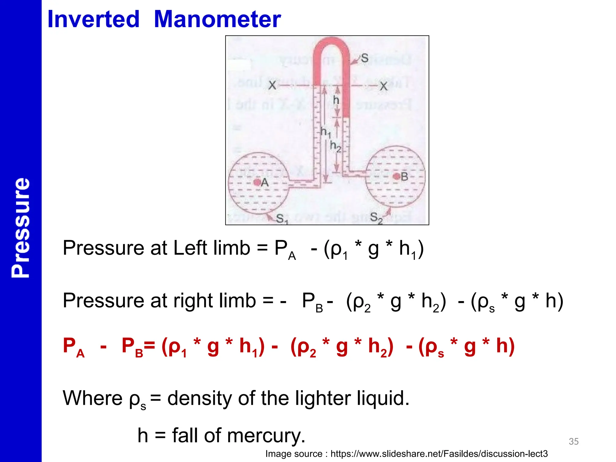
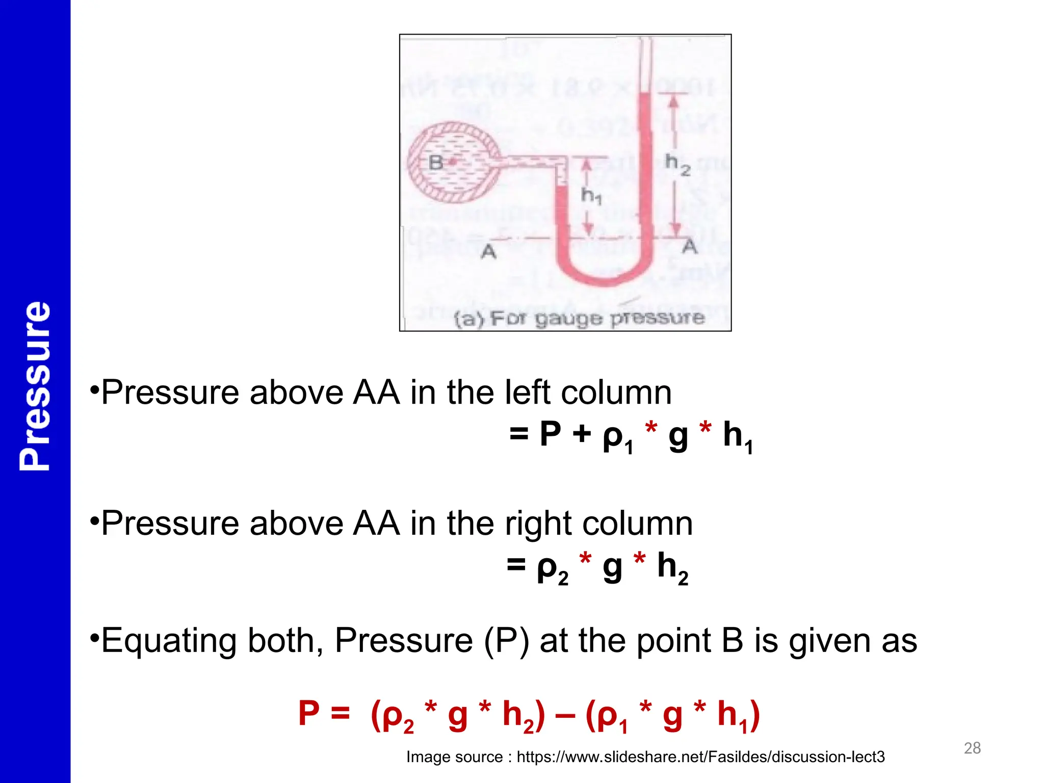
• Pressure above AA in the left column
= P + ρ1 * g * h1 + ρ2 * g * h2
• Pressure above AA in the right column = 0
• Equating both
P = - [ (ρ2 * g * h2) + (ρ1 * g * h1) ]
Image source :https://www.slideshare.net/Fasildes/discussion-lect3
31
Single Column Manometer
h1 = Height of the centre of pipe above XX.
h2 = Rise of heavy liquid in the right limb.
Δ h = Fall of mercury in a reservoir.
S1 = Specific gravity of the liquid in pipe.
S2 = Specific gravity of heavy liquid in reservoir and right
limb. https://www.slideshare.net/Fasildes/discussion-lect3
32
• ρ1 = Density of liquid in pipe.
• ρ2 = Density of heavy liquid in reservoir and right limb.
• P= Pressure to measured at point A.
• A= Cross sectional area of the reservoir.
• a = Cross sectional area of the right limb.
https://www.slideshare.net/Fasildes/discussion-lect3
33
•Fall of heavy liquid in reservoir will cause a rise of heavy liquid
level in right limb
A x Δ h = a h2
Δ h = a h2
A
•Considering the datum line YY
•Pressure in the right limb above YY = ρ2 * g * (Δ h + h2 )
•Pressure in the left limb above YY = P + ρ1 * g *(Δ h + h1 )
•Equating both and substituting Δ h from the above equation and
neglecting a/A ratio, the Pressure at the point A is given as
P = (ρ2 * g x * h2) - (ρ1 * g * h1)
34
Differential Manometer
Case A: Both Pipes at different levels
PA - PB= h * g *(ρg – ρ1 ) + (ρ2 * g * y) – (ρ1 * g * x)
Case B: Both Pipes at same levels
PA - PB= h * g *(ρg – ρ1)
Image source https://www.slideshare.net/Fasildes/discussion-lect3
35
Inverted Manometer
Pressure at Left limb = PA - (ρ1 * g * h1)
Pressure at right limb = - PB - (ρ2 * g * h2) - (ρs * g * h)
PA - PB= (ρ1 * g * h1) - (ρ2 * g * h2) - (ρs * g * h)
Where ρs = density of the lighter liquid.
h = fall of mercury.
Image source : https://www.slideshare.net/Fasildes/discussion-lect3
36
REFERENCES
1.Bansal, R.K., “Text book of Fluid Mechanics and Hydraulic
Machines”,
Laxmi Publications Ltd., New Delhi, 2005.
2. Modi, P.N. and Seth, S.M., ”Hydraulics and Fluid Mechanics
including
Hydraulics Machines”, Standard Book House, New Delhi, 2002.
3.https://www.slideshare.net/Fasildes/discussion-lect3.
4.https://www.quora.com/What-is-a-piezometer.
5.http://www.mechanicalbooster.com/2017/08/what-is-
capillarity.html.
6.http://www.eeeguide.com/surface-tension.

Mechanics-of-Fluids explained theory.ppt

  • 1.
    CEC 2103- MECHANICSOF FLUIDS III SEMESTER Dr.PRIYA VS Associate Professor SCHOOL OF INFRASTRUCTURE DEPARTMENT OF CIVIL ENGINEERING 1
  • 2.
    COURSE OBJECTIVE • Toimpart understanding of key concepts and fundamental principles pertaining to fluid behavior, both in static and flowing conditions. • To provide sufficient knowledge to analyze and design engineering systems and devices involving fluids and flow. • To enhance student’s interest in fluid phenomena and its applications 2
  • 3.
    COURSE OUTCOME At theend of the course, the student will be able to • Describe fluid properties, forces causing flow and will be able to solve problems involving fluid properties and fluid pressure measurements. • Compute the magnitude and location of hydrostatic forces on vertical, inclined and curved submerged surfaces and analyze the equilibrium of floating bodies. • Analyze the flow using principles of fluid kinematics 3
  • 4.
    4 • Solve fluidproblems using principle of fluid dynamics. • Describe the concepts of boundary layer theory, application off the concepts in determining the separation of boundary layer and to analyze the laminar and turbulent flows in circular pipes. • Apply the principles of dimensional analysis for fluid flow problems COURSE OUTCOME
  • 5.
    MODULE 1 Fluid propertiesand Pressure Measurement • Dimensions and units. • Properties of fluids. • Ideal and real fluid. • Definition of Pressure. • Pressure at a point. • Simple and differential manometer theory and Problems. • Pressure gauges. 5
  • 6.
    Fluid mechanics It isthe branch of science which deals with the behaviour of fluids at rest as well as in motion. Fluid static The study of fluid at rest. Fluid Kinematics The study of fluid in motion where pressure forces are not considered. Fluid Dynamics The study of fluids in motion where pressure forces are considered. 6
  • 7.
    Density Density or massdensity of a fluid is defined as the ratio of mass of fluid to its volume. ρ = Mass of fluid (kg) Volume of fluid (m3 ) Specific Weight or Weight Density Specific weight of a fluid is the ratio between the weight of a fluid to its volume. w = Weight of the fluid Volume of the fluid w = (Mass of the fluid x Acceleration due to gravity) volume of the fluid w = ρ x g 7
  • 8.
    Specific volume Specific volumeof the fluid is defined as the volume occupied by a unit mass of the fluid. Specific volume = Volume of the fluid (m3 ) Mass of the fluid (Kg) = 1/ ρ Specific Gravity Specific gravity is defined as the ratio of density of a fluid to the density of the standard fluid. S = Density of Liquid Density of water The standard fluid for liquid is water and for gas it is air. 8
  • 9.
    Viscosity Viscosity is definedas the property of a fluid which offers resistance to then movement of one layer of fluid over another adjacent layer of fluid. 9
  • 10.
    10 • Consider twolayers of fluid at a distance “dy” apart with velocity of “U” and “U + dU”. • Viscosity together with relative viscosity causes shear stress acting between fluid layers. • Shear stress is proportional to the rate of change of velocity with respect to “y”. Ԏ α du dy Ԏ = μ du dy
  • 11.
    • μ =Coefficient of dynamic viscosity or viscosity. • μ = Ԏ / (du/dy) • Viscosity is also defined as the shear stress required to produce unit rate of shear strain. Units : SI system : Ns/ m2 CGS system : dyne-sec/ cm2 (Poise ) Newton’s Law of Viscosity It states that the shear stress (Ԏ) of a fluid element layer is directly proportional to the rate of shear strain. 11
  • 12.
    Kinematic Viscosity Kinematic viscosityis defined as the ratio between the dynamic viscosity and density of fluid. Units : SI system : m2 /s CGS system : cm2 /s (Stokes) = ɣ Viscosity Density = ɣ μ ρ 12
  • 13.
    Ideal Plastic fluid NonNewtonian fluid Shear stress Velocity gradient Newtonian fluid Ideal Solids Ideal Liquid Types of Fluids •Ideal Fluid •Real Fluid •Newtonian Fluid •Non Newtonian Fluid 13
  • 14.
    14 Effect of Temperatureon Viscosity •Viscosity decreases with increase in temperature of liquid. •Viscous Forces • Cohesive Forces • Molecular momentum transfer •In liquid the cohesive forces dominates due to closely packed molecules and with the increase in temperature, the cohesive forces decreases hence decreasing the viscosity.
  • 15.
    Surface Tension Surface tensionis defined as the tensile force acting on the surface of the liquid in contact with gas or on the surface between two immiscible liquid. Surface tension on liquid droplet P = 4 σ d 15 Image source :http://www.eeeguide.com/surface-tension
  • 16.
    16 Surface tension ona hollow bubble P = 8 σ d Surface tension on a liquid jet P = σ * 2L L *d Where P = Pressure in N/ m2 σ = Surface tension in N/m d = diameter of the liquid droplet L = length of water jet Image source :http://www.eeeguide.com/surface-tension
  • 17.
    Capillarity Capillarity is definedas the phenomenon of rise or fall of a liquid surface in a small tube relative to adjacent general level of liquid when the tube is held vertically in the liquid. • Rise of liquid in the tube - Capillary rise • Fall of liquid in the tube - Capillary depression Factors affecting rise or fall 1.Denisty of liquid 2. Diameter of the tube 3.Surface tension of the liquid 17
  • 18.
    Expression for Capillaryrise 18 Image source ::hittp://www.mechanicalbooster.com/2017/08/what-is-capillarity.html Under state of equilibrium weight of the liquid of height is balanced by the force at the surface of the liquid in the tube Weight of liquid = ρ x g x Area of tube x h = ρ x g x π d2 x h 4
  • 19.
    19 • Vertical componentof the tensile force = σ x π d Cos θ • Equating two equations, • The capillary rise is given as h = 4 σ Cos θ ρ x g x d • θ = 0 for clean water and glass tube h = 4 σ ρ x g x d Where ρ= density; σ= surface tension; d = diameter of the tube
  • 20.
    20 Expression for Capillarydepression Image source :http://www.mechanicalbooster.com/2017/08/what-is-capillarity.html θ = 128 ° for mercury and glass tube Where ρ= density; σ= surface tension ;d = diameter of the tube If the glass tube is dipped in mercury the level of mercury in the tube is lower that the general level of the outside liquid. The capillary depression is h = - 4 σ Cos θ ρ x g x d
  • 21.
    21 The Pressure ona fluid is measured in two different systems Absolute Pressure: The Absolute pressure is defines as the pressure which is measured with reference to absolute vacuum pressure. Gauge Pressure: The Gauge pressure is defined as the pressure which is measured with the help of pressure measuring instrument, in which the atmospheric pressure is taken as datum.
  • 22.
    22 Absolute Pressure A B Gauge Pressure VacuumPressure Absolute Pressure Absolute Zero Pressure Vacuum Pressure: It is defined as the pressure below the atmospheric pressure.
  • 23.
    23 PRESSURE MEASUREMENT 1.Manometer :Devices used to measure the pressure at a point in a fluid by balancing the column of fluid by the same or another column of the fluid. 2.Mechanical Gauges : Devices used for measuring pressure by balancing the fluid column by the spring or dead weight. Absolute Pressure = Atmospheric Pressure + Gauge Pressure Vacuum Pressure = Atmospheric Pressure – Absolute Pressure
  • 24.
    24 Manometer 1. Simple Manometer 2.Differential Manometer Mechanical gauges 1. Bourdon tube pressure gauges 2. Dead-weight pressure gauges 3. Bellows pressure gauges
  • 25.
    25 Simple Manometer It consistsof a glass tube having one of its end connected to a point where pressure is to be measured and the other end remains open to atmosphere. The important types are 1. Piezometer. 2. U tube Manometer. 3. Single column manometer.
  • 26.
    26 Piezometer • Simplest methodto measure pressure. • The rise of liquid gives the pressure head at that point. • If at a point A, the height of liquid is h. • Pressure at point A is P = ρ * g * h Image source :https://www.quora.com/What-is-a-piezometer
  • 27.
    27 U Tube Manometer ForGauge Pressure Image source : https://www.slideshare.net/Fasildes/discussion-lect3 h1 = Height of the light liquid above datum line. h2 = Height of the heavy liquid above datum line. S1 = Specific gravity of the light liquid. S2 = Specific gravity of heavy liquid. ρ1 = Density of light liquid.
  • 28.
    28 •Pressure above AAin the left column = P + ρ1 * g * h1 •Pressure above AA in the right column = ρ2 * g * h2 •Equating both, Pressure (P) at the point B is given as P = (ρ2 * g * h2) – (ρ1 * g * h1) Image source : https://www.slideshare.net/Fasildes/discussion-lect3
  • 29.
    29 U Tube Manometer ForVacuum Pressure h1 = Height of the light liquid above datum line. h2 = Height of the heavy liquid above datum line. S1 = Specific gravity of the light liquid. S2 = Specific gravity of heavy liquid. ρ1 = Density of light liquid. ρ = Density of heavy liquid. Image source :https://www.slideshare.net/Fasildes/discussion-lect3
  • 30.
    30 • Pressure aboveAA in the left column = P + ρ1 * g * h1 + ρ2 * g * h2 • Pressure above AA in the right column = 0 • Equating both P = - [ (ρ2 * g * h2) + (ρ1 * g * h1) ] Image source :https://www.slideshare.net/Fasildes/discussion-lect3
  • 31.
    31 Single Column Manometer h1= Height of the centre of pipe above XX. h2 = Rise of heavy liquid in the right limb. Δ h = Fall of mercury in a reservoir. S1 = Specific gravity of the liquid in pipe. S2 = Specific gravity of heavy liquid in reservoir and right limb. https://www.slideshare.net/Fasildes/discussion-lect3
  • 32.
    32 • ρ1 =Density of liquid in pipe. • ρ2 = Density of heavy liquid in reservoir and right limb. • P= Pressure to measured at point A. • A= Cross sectional area of the reservoir. • a = Cross sectional area of the right limb. https://www.slideshare.net/Fasildes/discussion-lect3
  • 33.
    33 •Fall of heavyliquid in reservoir will cause a rise of heavy liquid level in right limb A x Δ h = a h2 Δ h = a h2 A •Considering the datum line YY •Pressure in the right limb above YY = ρ2 * g * (Δ h + h2 ) •Pressure in the left limb above YY = P + ρ1 * g *(Δ h + h1 ) •Equating both and substituting Δ h from the above equation and neglecting a/A ratio, the Pressure at the point A is given as P = (ρ2 * g x * h2) - (ρ1 * g * h1)
  • 34.
    34 Differential Manometer Case A:Both Pipes at different levels PA - PB= h * g *(ρg – ρ1 ) + (ρ2 * g * y) – (ρ1 * g * x) Case B: Both Pipes at same levels PA - PB= h * g *(ρg – ρ1) Image source https://www.slideshare.net/Fasildes/discussion-lect3
  • 35.
    35 Inverted Manometer Pressure atLeft limb = PA - (ρ1 * g * h1) Pressure at right limb = - PB - (ρ2 * g * h2) - (ρs * g * h) PA - PB= (ρ1 * g * h1) - (ρ2 * g * h2) - (ρs * g * h) Where ρs = density of the lighter liquid. h = fall of mercury. Image source : https://www.slideshare.net/Fasildes/discussion-lect3
  • 36.
    36 REFERENCES 1.Bansal, R.K., “Textbook of Fluid Mechanics and Hydraulic Machines”, Laxmi Publications Ltd., New Delhi, 2005. 2. Modi, P.N. and Seth, S.M., ”Hydraulics and Fluid Mechanics including Hydraulics Machines”, Standard Book House, New Delhi, 2002. 3.https://www.slideshare.net/Fasildes/discussion-lect3. 4.https://www.quora.com/What-is-a-piezometer. 5.http://www.mechanicalbooster.com/2017/08/what-is- capillarity.html. 6.http://www.eeeguide.com/surface-tension.