Download to read offline

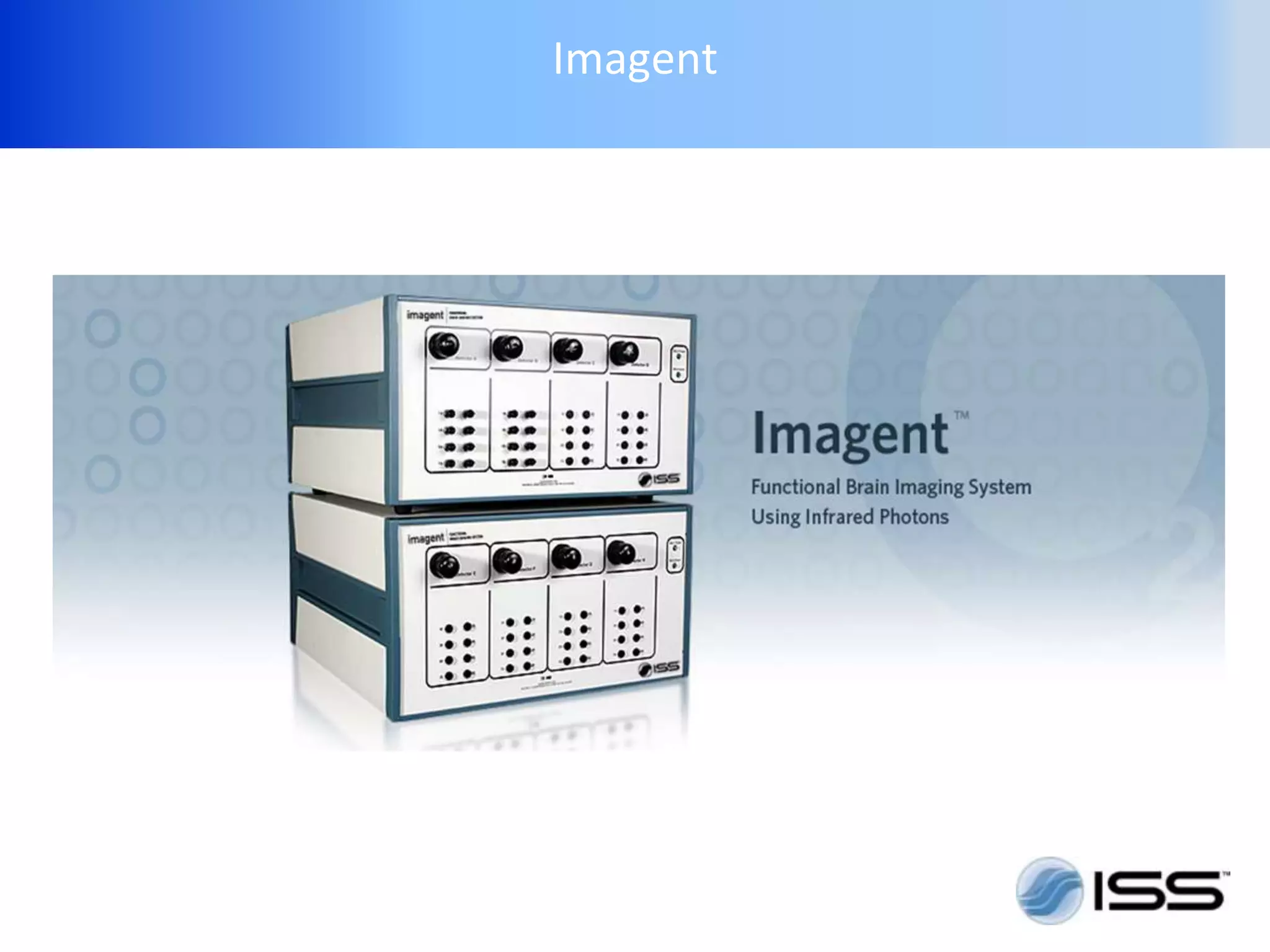
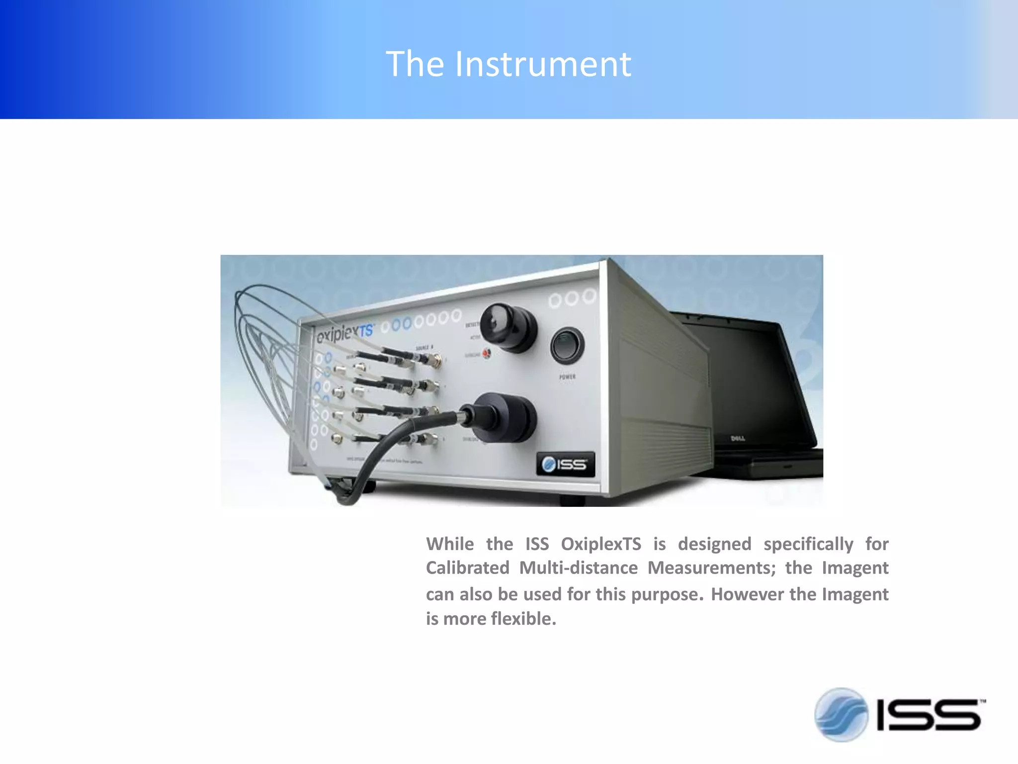
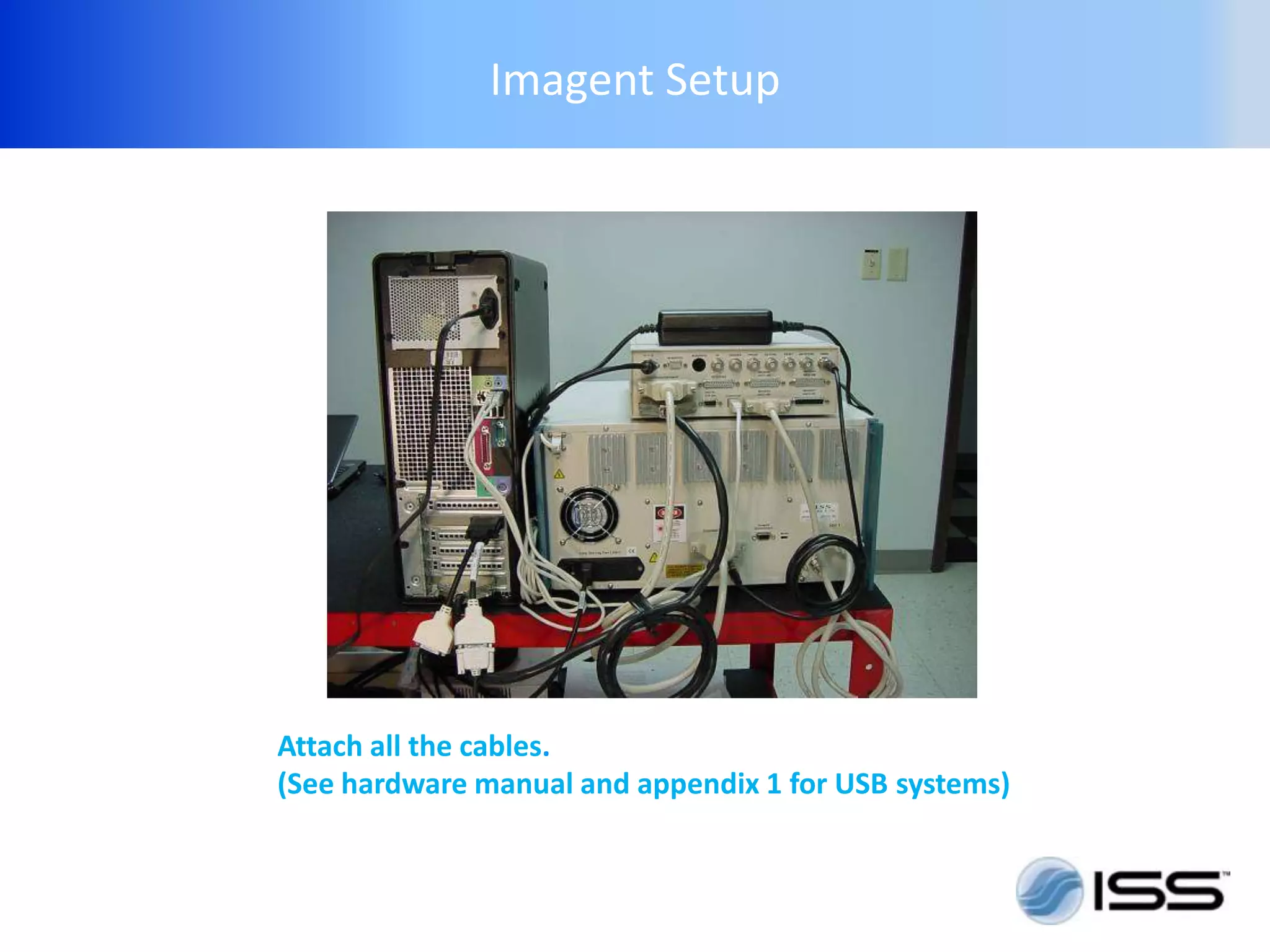
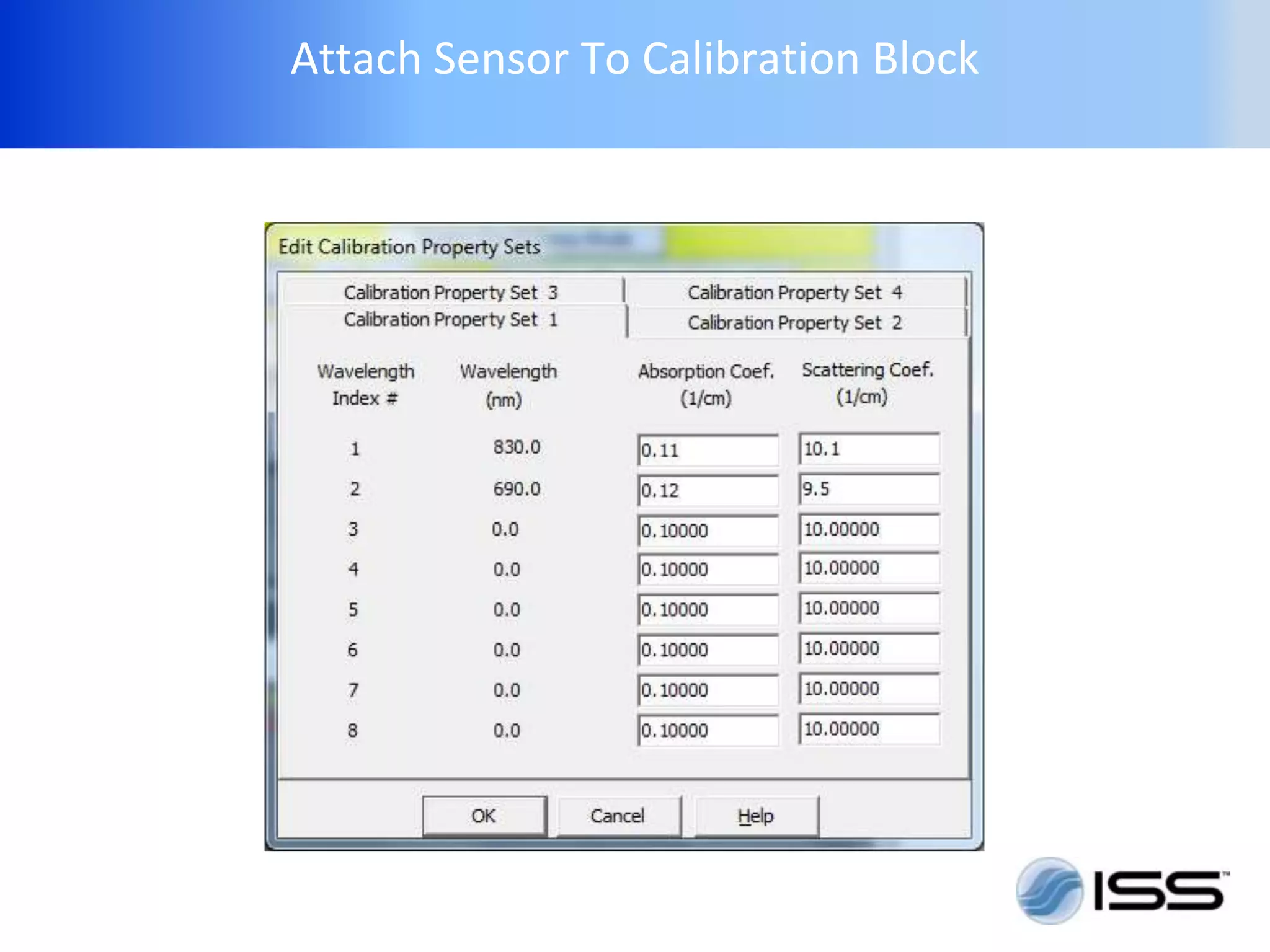
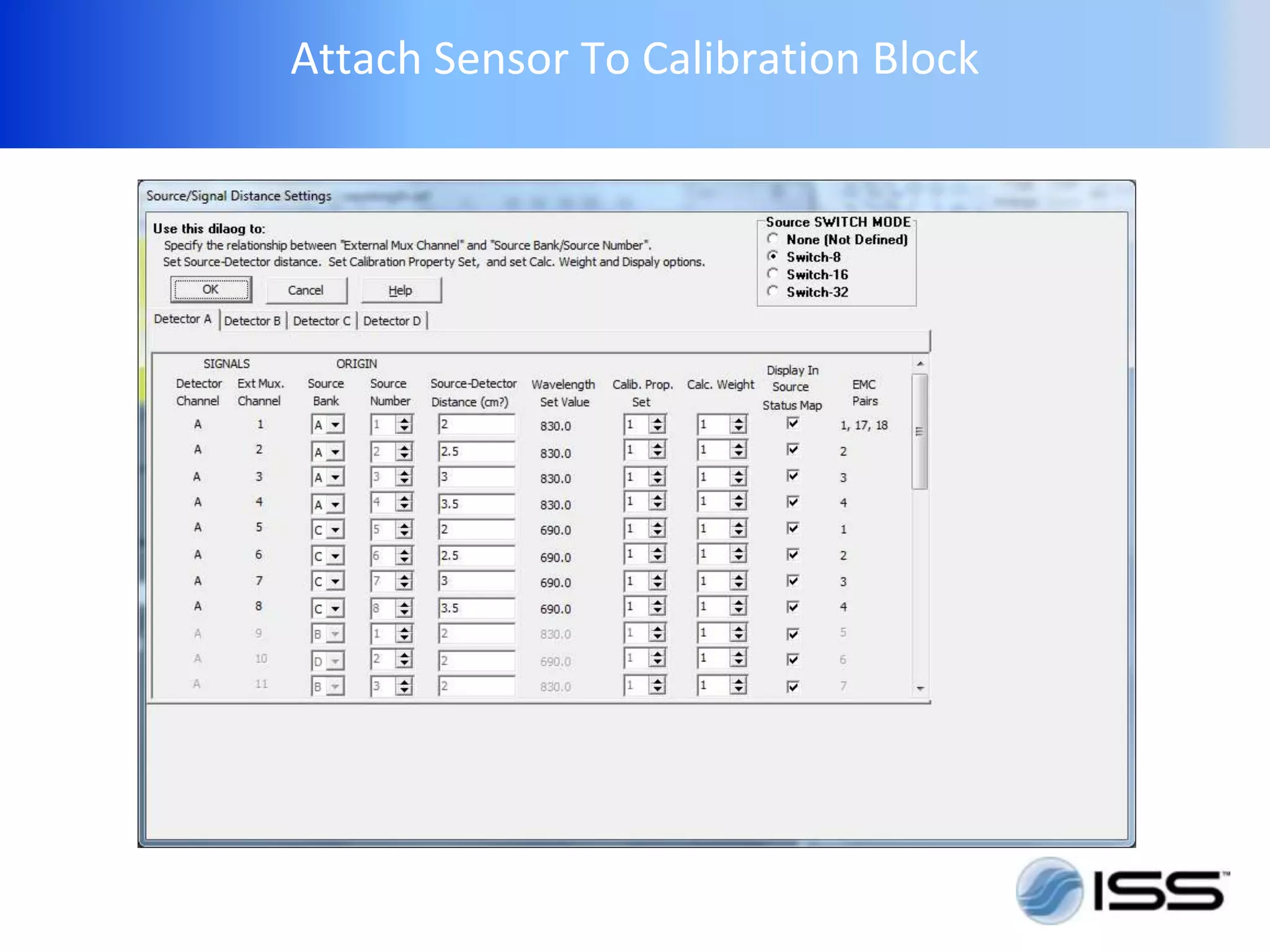

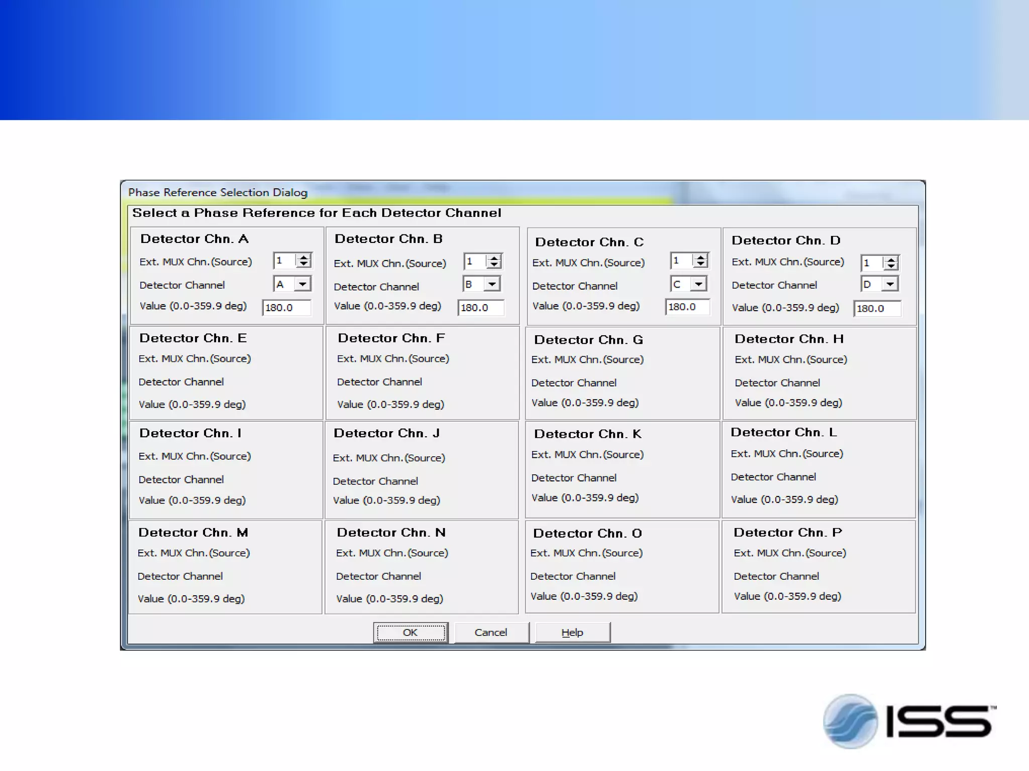
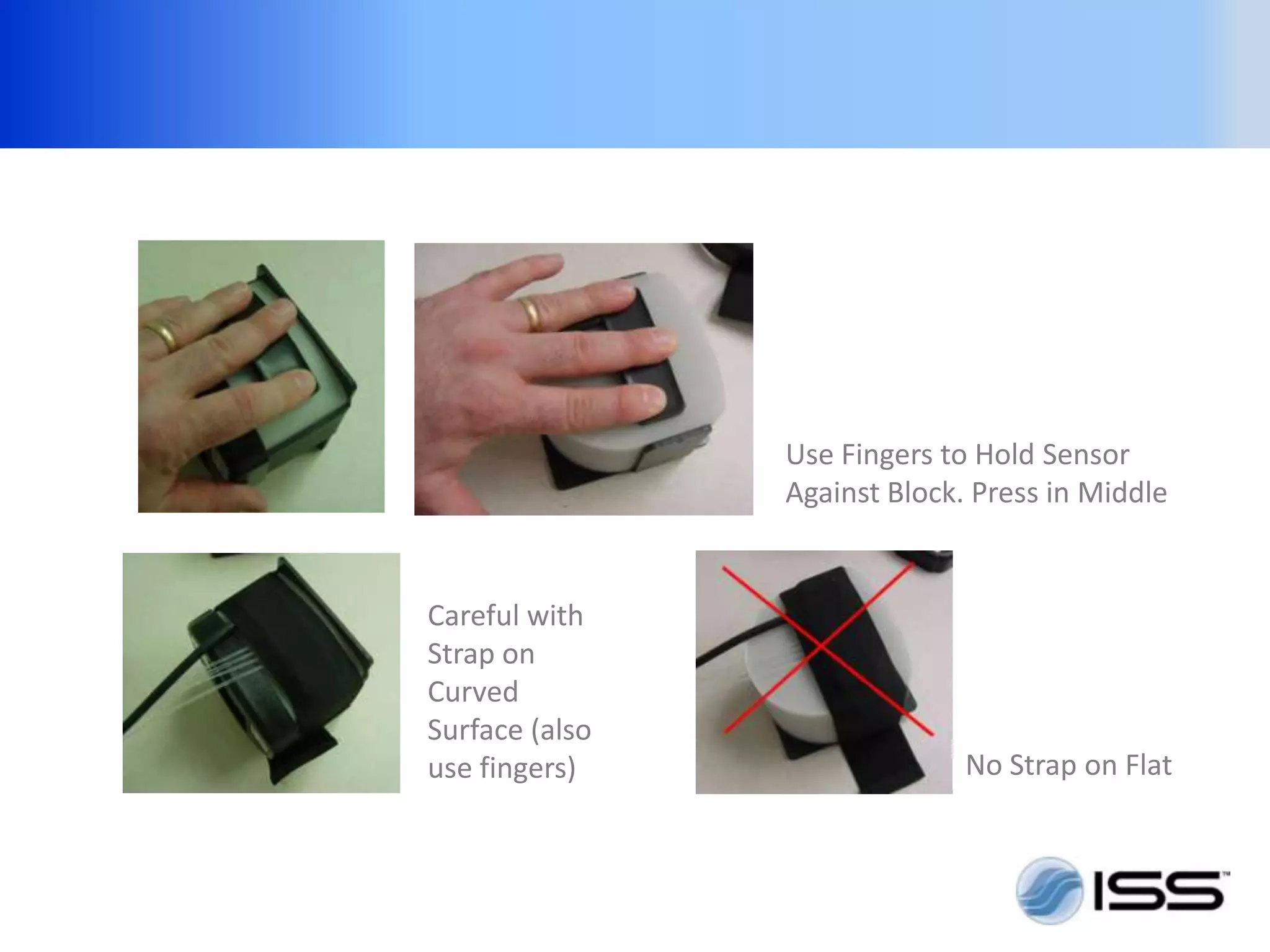
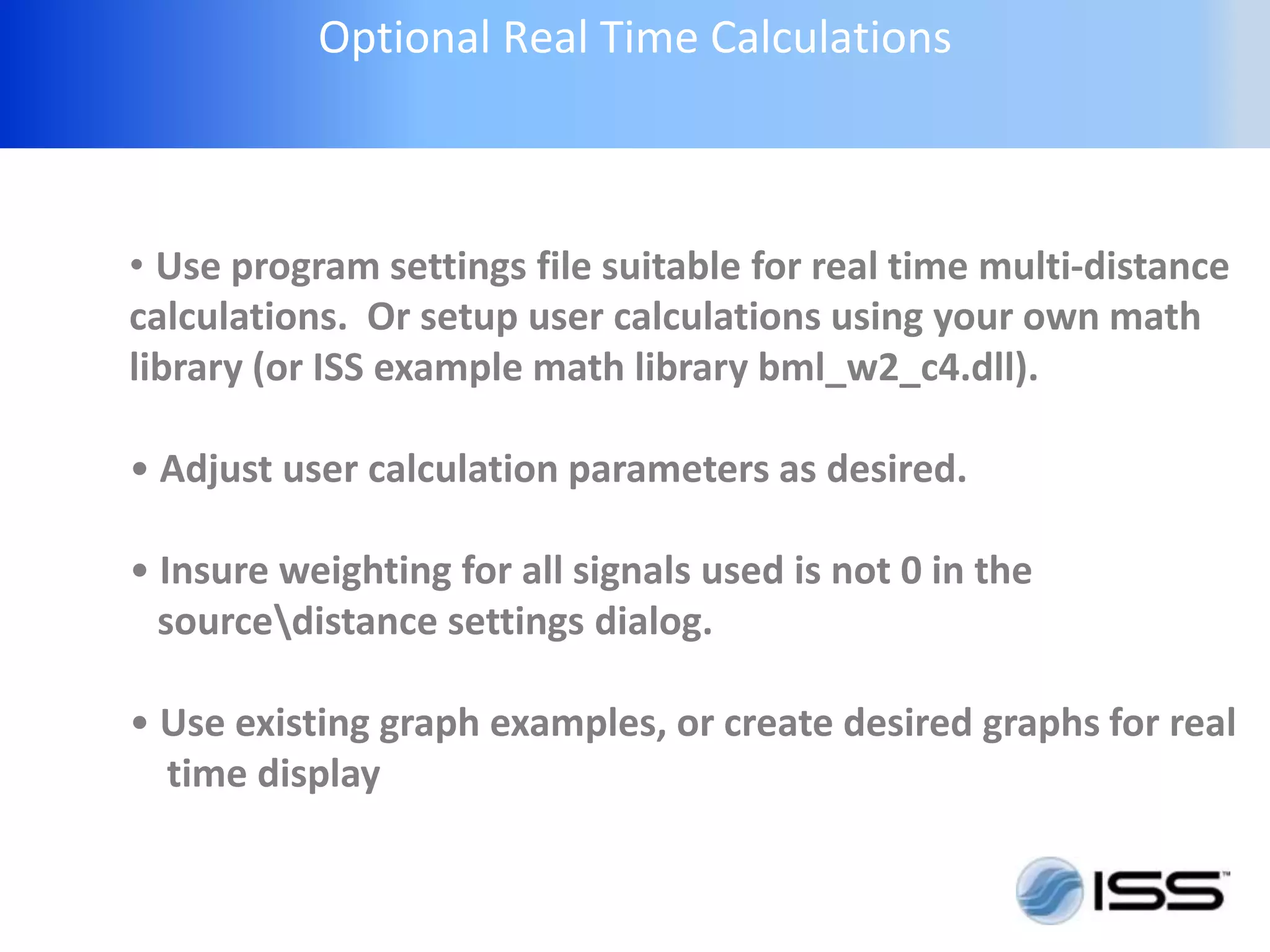


This document provides instructions for setting up and using the Imagent instrument for calibrated multi-distance measurements. The Imagent is more flexible than other instruments like the ISS OxiplexTS, but requires similar steps: 1) Setup the instrument and cables, 2) Check the instrument is functioning properly, 3) Calibrate the instrument using a calibration block, and 4) Take measurements and record the data. Key steps include warming up the instrument, selecting and attaching sensors, optimizing detector gain, and running the calibration process in the software. Real-time calculations can also be performed to further analyze data quality during measurements.