Downloaded 15 times


![Last updated: 21.03.07
26 av 27
GIF/EELS
Forberedelse:
• Slå på cooler for CCD kamera (under høyre skjerm)
• Slå på kamerakontroll Beamstop out
amera out
Gain auto
• Skriv EXT_1 for å gi TEM datastyring
• Slå på TV skjerm (bryter i inn posisjon)
• Slå på dataprogram: venstre Filter Controll og høyre EL/P3.03 samt Digital Michrograph (eventuelt
passord: ok) (strøm 200)
Opplinjering:
• [TEM] mode
• [Align ZLP] på høyre skjerm
• Mode-spectroscopy, venstre skjerm
• Appertur på: mask, slit ut. Dette for ikke å brenne skjermen.
• Samle strålen, TV camera inn.
• Styr spektret med opp og ned piltastene.
• Fokus X, justeres med å bevege musen
• Fokus Y, justeres med å bevege musen
• SX
• SY....Acomp –Bcomp.
• TV kamera ut
• Align ZLP enda en gang, 3,0mm?
• Mode-imaging
• Appertur 3,0mm (for tuning og gain)
Tykkelsesmåling :
• Slå på [TEM] mode
• Sett strålen i hullet
• Juster strålen start med liten intensitet og jobb nedover (må ha stor intensitet for at det skal fungere)
• Camera-preper gain ref-TI:8000(counts), FA:5(bilder)-OK (dette for å justere bakgrunnsintensiteten på
pixlene) Høyre skjerm
• Slå på [EELS] mode
• Fyll nesten hele skjermen, jobb nedover helt til du ikke får proceed mer.
• Trykk [IDLE] høyre skjerm.
• Stopp hvis høyre knapp lyser rødt og juster intensitet, spre med klokka.
• Hele grovspektret må vises.
• Trykk [option] på tastatur samt [SURVEY] på knapprad på høyre skjerm, sett exp tid til 0,2. Kan også
justeres med piltaster på skjerm og keyboard.
• Eventuelt sett strålen på ønsket område.
• Trykk [IDLE]
• Finn ZLP og sett denne på ca 100 med energy shift på venstre skjerm
• Filter-acquire EELS spectre
• Calibrate-Energy scale, null linje settes til 0, Low(0) og step (0,3)
• Analyse-compute thickness
• Med 200KV er MFP=90nm, maks måletykkelse 144nm
Digitale bilder:
• Sett prøven i et Hull
• Slå på [TEM] mode
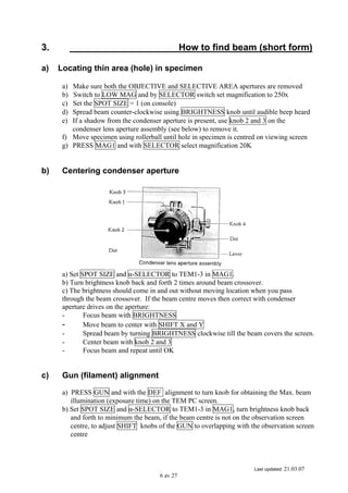
• [TUNE GIF] høyre skjerm, slit with 20eV](https://image.slidesharecdn.com/jeol2010basiceasyusing-140813125551-phpapp01/85/Jeol-2010-basic_easyusing-26-320.jpg)
![Last updated: 21.03.07
27 av 27
• Juster strålen slik at markøren er på grønt område, når dette er ok trykk ENTER.
• Kjør Gain.ref (Tune Gif)
• Sett strålen på prøven
• Slå på [EELS] mode
• Sett venstre skjerm på IMAGEING
• Custom- 1000 mag for å kompensere for forstørrelsesforskjell X20
• Sett mikroskopet på x2000, som nå egentlig er x1000
• Ta opp skjerm
• TV kamera inn
• Skru av eventuell: offset
• Fokuser bildet på ønsket område
• TV kamera ut
• Slå på [TEM] mode
• [IDLE] [SEARCH] for hurtigbilde av området
• [FOCUS] [IDLE] for fokusering, kan justere exp tid med piltaster eller option-survey
• [PREVIEW] for forhåndsvisning
• Ta bilde med kamera ikon nederst til venstre på skjermen
• File- save as, hvis man ønsker å lagre
EFTEM
• Finn eventuelt ønsket topp i [EELS] mode, trenger ikke gjøre dette
• Bruk offset funksjonen for å få ZLP ut av bilde, unngår for høy intensitet.
• EFTEM
• [CUSTOM]
• [MAP X]
• Exp tid 20s
• Trykk gjennom alternativene til man kan sette inn ønsket element
• Kan også bruke [COMPUTE RATIO] fjerner tykkelseseffekter og diff kontrast
• Avslutt analyse med Custom-Free lens off with page mikroskopet får kontroll over linsen.
• EXT_0 på keyboard
• Dobbeltopper: justeres med AC comp.
[XXXX]=knapp på skjermen
Kursiv =Menylinje helt øverst](https://image.slidesharecdn.com/jeol2010basiceasyusing-140813125551-phpapp01/85/Jeol-2010-basic_easyusing-27-320.jpg)

This document provides guidelines for operating the JEOL 2010 TEM located at the NTNU Department of Materials Technology Electron Microscopy Laboratories. It discusses sample insertion and filament procedures, how to locate the beam, perform basic imaging modes like bright field and dark field, take photos, and perform techniques like CBD and EDS. The final section covers properly ending a session, including removing the sample, turning off the filament and high tension, and draining remaining liquid nitrogen from the cold trap. Users are reminded to follow all safety procedures and to properly document any issues in the log books.


![2. [pro forma] camera getting started guide(4)](https://cdn.slidesharecdn.com/ss_thumbnails/2-170705214618-thumbnail.jpg?width=640&height=640&fit=bounds)


