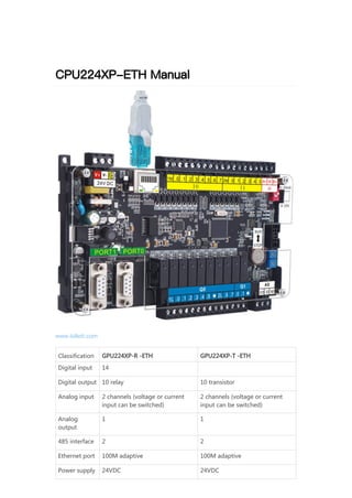
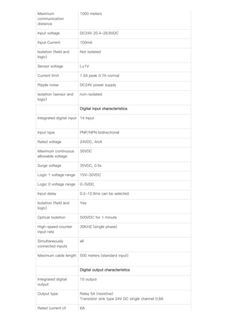
CPU224XP-ETH Manual
www.lollett.com
Classification GPU224XP-R -ETH GPU224XP-T -ETH
Digital input 14
Digital output 10 relay 10 transistor
Analog input 2 channels (voltage or current
input can be switched)
2 channels (voltage or current
input can be switched)
Analog
output
1 1
485 interface 2 2
Ethernet port 100M adaptive 100M adaptive
Power supply 24VDC 24VDC
Note: Comes with 10/100M Ethernet port, similar to CP243 functional module, can
download monitoring program through network interface, support S7 communication
protocol and MODBUS TCP communication protocol
Features
1) Fully compatible with S7 programming software and instruction set.
2) 14 channels of digital input; 10 channels of digital output; 2 channels of analog
analog input, built-in DIP switch, voltage or current input can be set; 1 channel of
analog output, output voltage and current at the same time.
3) The digital input port adopts bidirectional optocoupler and supports NPN or PNP
input.
4) The analog input adopts high-precision AD and rail-to-rail operational amplifier,
which can realize low-voltage recognition.
5) 2-channel PPI communication interface, supporting 187.5k baud rate. With one
Ethernet port, you can download and monitor programs via Ethernet.
6) Support PPI protocol, Modbus protocol, Freeport protocol, USS protocol, support S7
Ethernet protocol, Modbus TCP protocol.
7) Built-in clock battery, dual-circuit power supply design, support perpetual calendar
standby use for more than 2 years.
8) Unbreakable after encryption, completely protect your program.
9) Using FLASH technology, no need for battery support, permanent storage.
10) Anti-reverse connection design for power supply; electrostatic protection design for
communication port; analog short-circuit protection.
11) Support PID instruction, which can facilitate users to realize multi-channel PID
control.
12) The power board uses solid materials and sufficient power to meet multiple
expansion and sensor power supply;
13) After strict industrial field test and environmental test.
14) Transistor model products, support 100K high-speed pulse output.
15) Support 7 external expansion modules, and support mixed use with Siemens
modules.
Wiring
CPU224XP-T-ETH-(transistor-type)-wiring-diagram
CPU224XP-R-ETH (relay type) wiring diagram
Technical Parameters
Model CPU224XP-R/T(-ETH)
Power Consumption 7W
Program memory 16K
Data storage 10K
Digital input 14
Digital output 10
Digital IO mapping
area
256(128DI/128DO)
Analog IO mapping
area
64(32AI/32AO)
Maximum expansion
module
7
High-speed pulse
input
6 X 30K
High-speed pulse
output
2 X 100K
Total number of
timers
256
Total number of
counters
256
Analog potentiometer 2 X 8Bit
Time interruption 2 *1mS resolution
Real Time Clock Support, built-in battery
Boolean instruction
efficiency
0.28uS
Floating point
instruction efficiency
0.75uS
interface 2*RS-485,standard PPI communication ports
PPI baud rate 9.6k, 19.2k and 187.5kbps
Free port baud rate 1.2k-115.2kbps
Maximum cable length
per section
Using isolated repeater: 187.5kbps up to 1000 meters,
38.4kbps up to 1200 meters; not using isolated repeater: 50
meters
Maximum number of
stations
32 stations per segment, 126 stations per network
Maximum number of
master stations
32
Number of interfaces 1
Mode 10/100Mbit/s
Protocol S7 Ethernet protocol (support server mode)
Modbus TCP protocol (support server and client mode)
Maximum
communication
distance
1000 meters
Input voltage DC24V 20.4-28.8VDC
Input Current 100mA
Isolation (field and
logic)
Not isolated
Sensor voltage L±1V
Current limit 1.5A peak 0.7A normal
Ripple noise DC24V power supply
Isolation (sensor and
logic)
non-isolated
Digital input characteristics
Integrated digital input 14 Input
Input type PNP/NPN bidirectional
Rated voltage 24VDC, 4mA
Maximum continuous
allowable voltage
30VDC
Surge voltage 35VDC, 0.5s
Logic 1 voltage range 15V-30VDC
Logic 0 voltage range 0-5VDC
Input delay 0.2-12.8ms can be selected
Isolation (field and
logic)
Yes
Optical isolation 500VDC for 1 minute
High-speed counter
input rate
30KHZ (single phase)
Simultaneously
connected inputs
all
Maximum cable length 500 meters (standard input)
Digital output characteristics
Integrated digital
output
10 output
Output type Relay 5A (resistive)
Transistor sink type 24V DC single channel 0.8A
Rated current of 6A
common terminal
Resistance (contact) 0.2Ω typical (0.6Ω maximum)
Photoelectric isolation
(field to isolation)
500VAC, 1 minute
Simultaneously
connected output
At 60°C, all outputs (horizontal installation) At 50°C, all outputs
(vertical installation)
Two parallel outputs Yes, only when the same group is output
Shield 500 meters
Analog input characteristics
The machine’s
integrated input points
2
input method Single-ended input
Analog input
characteristics
0~10V / 0~20mA
input resistance Voltage type 30K ,current type 120Ω
Data Format 0~32000
Resolution 12 bits with sign bit
Error Worst case, 0° to 55°C ± 2.5% of full scale
Typical, 25°C ±1.0% of full scale
Repeatability ± 0.05% of full scale
Analog to digital
conversion time
100ms
Analog output characteristics
The machine’s
integrated input points
1
Output voltage range 0~10V
Output current
rangeOutput current
range
0~20mA
Data Format 0~32000
Error Worst case, 0° to 55°C ± 3% of full scale
Typical, 25°C ±2.5% of full scale
Repeatability ± 1% of full scale
Conversion time 50uS
Load capacity 0~10V >5KΩ 0~20mA <500Ω
Size (W x H x D)mm 150x106x35
Communication interface definition
Analog interface definition
PIN Port1 Port0
1 Shell Ground Shell Ground
2 +24V Ground +24V Ground
3 RS485 signal A RS485 signal A
4 Send application RTS Send application RTS
5 +5V Ground +5V Ground
6 +5V +5V
7 +24V +24V
8 RS485 signal B RS485 signal B
9 NC NC
A+: AIW0 channel,
0-10V or 0-20mA input
M: analog input common terminal
B+: AIW2 channel,
0-10V or 0-20mA input
4-20mA Transmitter Wiring Diagram
Note: The analog input supports voltage or current input, which can be
selected by the DIP switch on the right. DIP 1 corresponds to A+ channel,
DIP 2 corresponds to B+ channel, ON current input, OFF voltage input
1
V0: AQW0 channel, 0-10V output;
M: analog output common terminal;
B+: AQW0 channel, 0-20mA output;
Note: The analog output channel outputs voltage and current at the same
time, both of which are controlled by AQW0
1
4-20mA two-wire and three-wire transmitter wiring diagram
Internal schematic diagram of transistor output
Note: Before connecting the current signal, the analog input should be set
to the current input mode through the red dial switch
1
Dimensions
https://www.xueplc.com/cpu224xp-eth-manual.html

Cpu224 xp eth-manual

  • 1.
    CPU224XP-ETH Manual www.lollett.com Classification GPU224XP-R-ETH GPU224XP-T -ETH Digital input 14 Digital output 10 relay 10 transistor Analog input 2 channels (voltage or current input can be switched) 2 channels (voltage or current input can be switched) Analog output 1 1 485 interface 2 2 Ethernet port 100M adaptive 100M adaptive Power supply 24VDC 24VDC
  • 2.
    Note: Comes with10/100M Ethernet port, similar to CP243 functional module, can download monitoring program through network interface, support S7 communication protocol and MODBUS TCP communication protocol Features 1) Fully compatible with S7 programming software and instruction set. 2) 14 channels of digital input; 10 channels of digital output; 2 channels of analog analog input, built-in DIP switch, voltage or current input can be set; 1 channel of analog output, output voltage and current at the same time. 3) The digital input port adopts bidirectional optocoupler and supports NPN or PNP input. 4) The analog input adopts high-precision AD and rail-to-rail operational amplifier, which can realize low-voltage recognition. 5) 2-channel PPI communication interface, supporting 187.5k baud rate. With one Ethernet port, you can download and monitor programs via Ethernet. 6) Support PPI protocol, Modbus protocol, Freeport protocol, USS protocol, support S7 Ethernet protocol, Modbus TCP protocol. 7) Built-in clock battery, dual-circuit power supply design, support perpetual calendar standby use for more than 2 years. 8) Unbreakable after encryption, completely protect your program. 9) Using FLASH technology, no need for battery support, permanent storage. 10) Anti-reverse connection design for power supply; electrostatic protection design for communication port; analog short-circuit protection. 11) Support PID instruction, which can facilitate users to realize multi-channel PID control. 12) The power board uses solid materials and sufficient power to meet multiple expansion and sensor power supply; 13) After strict industrial field test and environmental test. 14) Transistor model products, support 100K high-speed pulse output. 15) Support 7 external expansion modules, and support mixed use with Siemens modules. Wiring
  • 3.
    CPU224XP-T-ETH-(transistor-type)-wiring-diagram CPU224XP-R-ETH (relay type)wiring diagram Technical Parameters Model CPU224XP-R/T(-ETH) Power Consumption 7W
  • 4.
    Program memory 16K Datastorage 10K Digital input 14 Digital output 10 Digital IO mapping area 256(128DI/128DO) Analog IO mapping area 64(32AI/32AO) Maximum expansion module 7 High-speed pulse input 6 X 30K High-speed pulse output 2 X 100K Total number of timers 256 Total number of counters 256 Analog potentiometer 2 X 8Bit Time interruption 2 *1mS resolution Real Time Clock Support, built-in battery Boolean instruction efficiency 0.28uS Floating point instruction efficiency 0.75uS interface 2*RS-485,standard PPI communication ports PPI baud rate 9.6k, 19.2k and 187.5kbps Free port baud rate 1.2k-115.2kbps Maximum cable length per section Using isolated repeater: 187.5kbps up to 1000 meters, 38.4kbps up to 1200 meters; not using isolated repeater: 50 meters Maximum number of stations 32 stations per segment, 126 stations per network Maximum number of master stations 32 Number of interfaces 1 Mode 10/100Mbit/s Protocol S7 Ethernet protocol (support server mode) Modbus TCP protocol (support server and client mode)
  • 5.
    Maximum communication distance 1000 meters Input voltageDC24V 20.4-28.8VDC Input Current 100mA Isolation (field and logic) Not isolated Sensor voltage L±1V Current limit 1.5A peak 0.7A normal Ripple noise DC24V power supply Isolation (sensor and logic) non-isolated Digital input characteristics Integrated digital input 14 Input Input type PNP/NPN bidirectional Rated voltage 24VDC, 4mA Maximum continuous allowable voltage 30VDC Surge voltage 35VDC, 0.5s Logic 1 voltage range 15V-30VDC Logic 0 voltage range 0-5VDC Input delay 0.2-12.8ms can be selected Isolation (field and logic) Yes Optical isolation 500VDC for 1 minute High-speed counter input rate 30KHZ (single phase) Simultaneously connected inputs all Maximum cable length 500 meters (standard input) Digital output characteristics Integrated digital output 10 output Output type Relay 5A (resistive) Transistor sink type 24V DC single channel 0.8A Rated current of 6A
  • 6.
    common terminal Resistance (contact)0.2Ω typical (0.6Ω maximum) Photoelectric isolation (field to isolation) 500VAC, 1 minute Simultaneously connected output At 60°C, all outputs (horizontal installation) At 50°C, all outputs (vertical installation) Two parallel outputs Yes, only when the same group is output Shield 500 meters Analog input characteristics The machine’s integrated input points 2 input method Single-ended input Analog input characteristics 0~10V / 0~20mA input resistance Voltage type 30K ,current type 120Ω Data Format 0~32000 Resolution 12 bits with sign bit Error Worst case, 0° to 55°C ± 2.5% of full scale Typical, 25°C ±1.0% of full scale Repeatability ± 0.05% of full scale Analog to digital conversion time 100ms Analog output characteristics The machine’s integrated input points 1 Output voltage range 0~10V Output current rangeOutput current range 0~20mA Data Format 0~32000 Error Worst case, 0° to 55°C ± 3% of full scale Typical, 25°C ±2.5% of full scale Repeatability ± 1% of full scale Conversion time 50uS Load capacity 0~10V >5KΩ 0~20mA <500Ω Size (W x H x D)mm 150x106x35
  • 7.
    Communication interface definition Analoginterface definition PIN Port1 Port0 1 Shell Ground Shell Ground 2 +24V Ground +24V Ground 3 RS485 signal A RS485 signal A 4 Send application RTS Send application RTS 5 +5V Ground +5V Ground 6 +5V +5V 7 +24V +24V 8 RS485 signal B RS485 signal B 9 NC NC A+: AIW0 channel, 0-10V or 0-20mA input M: analog input common terminal B+: AIW2 channel, 0-10V or 0-20mA input
  • 8.
    4-20mA Transmitter WiringDiagram Note: The analog input supports voltage or current input, which can be selected by the DIP switch on the right. DIP 1 corresponds to A+ channel, DIP 2 corresponds to B+ channel, ON current input, OFF voltage input 1 V0: AQW0 channel, 0-10V output; M: analog output common terminal; B+: AQW0 channel, 0-20mA output; Note: The analog output channel outputs voltage and current at the same time, both of which are controlled by AQW0 1
  • 9.
    4-20mA two-wire andthree-wire transmitter wiring diagram Internal schematic diagram of transistor output Note: Before connecting the current signal, the analog input should be set to the current input mode through the red dial switch 1
  • 10.