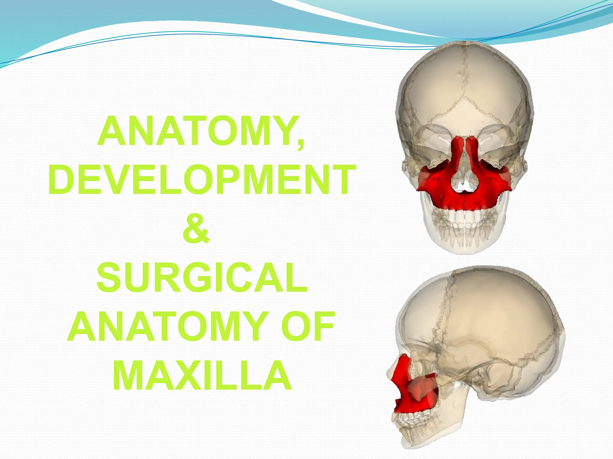
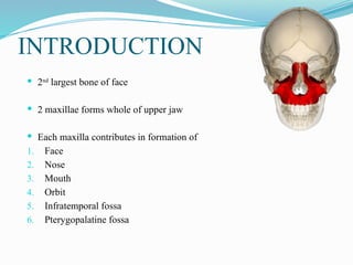
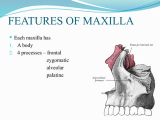
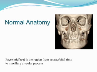
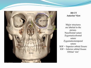
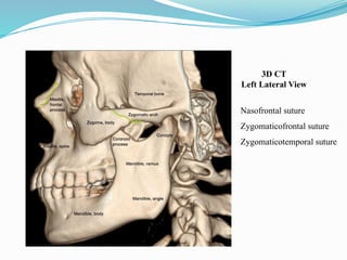
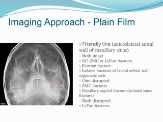
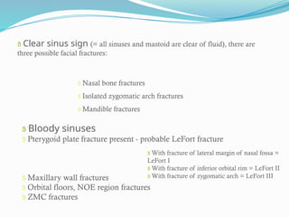
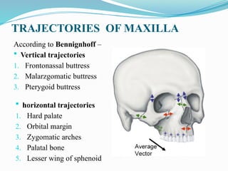
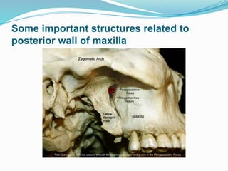
ANATOMY,
DEVELOPMENT
&
SURGICAL
ANATOMY OF
MAXILLA
INCLUSIONS
 INTRODUCTION
 FEATURES OF MAXILLA
 DEVELOPMENT
 SURGICAL ANATOMY
 CONCLUSION
 RESOURCES
INTRODUCTION
 2nd
largest bone of face
 2 maxillae forms whole of upper jaw
 Each maxilla contributes in formation of
1. Face
2. Nose
3. Mouth
4. Orbit
5. Infratemporal fossa
6. Pterygopalatine fossa
FEATURES OF MAXILLA
 Each maxilla has
1. A body
2. 4 processes – frontal
zygomatic
alveolar
palatine
BODY OF MAXILLA
 Shape – pyramidal
 It has –
1. Base – directed medially at nasal surface
2. Apex - directed laterally at zygomatic process
3. 4 surfaces – anterior / facial
posterior / infratemporal
medial / nasal
superior / orbital
Encloses a cavity – maxillary sinus
ANTERIOR / FACIAL SURFACE
 Directs laterally
 Incisive fossa -depressor septi
 Incisivus – alveolar margin
 Nasalis – superiolateral, along nasal notch
 Canine fossa – levator anguli oris
 Infraorbital foramen
 levator labii superioris
 Medially – the nasal notch
- anterior nasal spine
POSTERIOR / INFRATEMPORAL SURFACE
 Concave
 Directed – backward & laterally
 Forms – anterior wall of infratemporal fossa
 Separated from anterior surface
 2-3 alveolar canals for – posterior superior
alveolar nerve
 Posteroinferiorly – maxillary tuberosity &
superficial head of medial pterygoid muscle
 Above maxillary tuberosity -anterior wall of
infratemporal fossa, grooved by maxillary
nerve
SUPERIOR / ORBITAL SURFACE
 Smooth, triangular & slightly concave
 Forms – Greater Part Of Floor Of Orbit
 Anterior border forms – part of inferior orbital margin
continues with lacrymal crest of frontal process
Posterior border –
smooth & rounded
Forms most anterior margin of
inferior orbital fissure
In middle – infraorbital groove
Medial border –
Anteriorly lacrymal notch, converted into nasolacrymal canal
Behind the notch, articulation with -
Lacrymal
Labrynth of ethmoid
Orbital process of palatine bone
The superior surface presents –
 Infraorbital groove & canal
 Canalis sinosus
 Inferior oblique muscles
THE MEDIAL /NASAL SURFACE
 Part of lateral wall of nose
 Posterosuperiorly – maxillary hiatus
 Above the hiatus – air sinuses
 Below the hiatus – anterior part of inferior meatus
 Behind the hiatus –
articulates with
perpendicular plate of
palatine bone
&
encloses greater
& lesser palatine canals
THE MEDIAL /NASAL SURFACE
 Infront of the hiatus – nasolacrymal groove articulates with
descending process of lacrymal bone & lacrymal process of
inferior nasal concha to forms nasolacrymal canal
THE MEDIAL /NASAL SURFACE
 More anteriorly – conchal creast for articulation with inferior
nasal concha.
 Above the conchal crest – atrium of middle meatus.
PROCESSES
OF
MAXILLA
1. FRONTAL
2. ZYGOMATIC
3. ALVEOLAR
4. PALATINE
FRONTAL PROCESS
 Projects upward & backwards to articulate
above – nasal margin of frontal bone
infront – nasal bone
behind – lacrymal bone
 Lateral surface – divided by anterior lacrymal crest into
anterior smooth & posterior grooved
 anterior lacrymal crest
gives attachment to
lacrymal fascia &
medial palpebral ligament
FRONTAL PROCESS
 Medial surface – forms lateral wall of nose
from above downwards –
1. Uppermost roughened area for articulation with ethmoid
2. Ethmoidal crest – a horizontal ridge, articulates with middle nasal
concha
3. Below the ethmoidal crest
– atrium of middle meatus
conchal crest
inferior meatus
 Pyramidal lateral projection
 Anterior, posterior & superior surfaces converge here
 Superiorly – rough, to articulate with zygomatic bone
ZYGOMATIC PROCESS
 Forms half of alveolar arch
 Bears socket for maxillary teeth
 In adults = 8 sockets
 Buccinator arises from posterior part of its outer surface upto
1st
molar tooth.
 Maxillay torus (occasionally)
ALVEOLAR PROCESS
 Thick horizontal plate
 Projecting medially
 Forms largest part of roof & floor
 Inferior surface – concave & forms anterior 3/4th
of bony hard
palate.
PALATINE PROCESS
 Various foramina & pits
 Posterolaterally –
greater & lesser
palatine foremen
 Superior surface –concave
from side to side & forms
floor of nasal cavity.
Medial border –
 Thicker anteriorly
 Groove between
nasal crest of 2 maxilla
receives lower border Vomer
Anterior part of ridge – incisal crest & anterior nasal spine, Incisive canal
Posterior border articulates with horizontal plate of palatine bone
Lateral border is continuous with alveolar process
ARTICULATIONS OF MAXILLA
 Superiorly – 3 bones
1. Frontal
2. Nasal
3. Lacrymal
 Laterally – 1 bone
1. Zygomatic bone
ARTICULATIONS OF MAXILLA
Medially – 5 bones
1. Ethmoid
2. Inferior nasal concha
3. Vomer
4. Palatine
5. Opposite maxilla
AGE CHANGES IN MAXILLA
 AT BIRTH –
1. Transverse & anterioposterior diameter > vertical diameter
2. Well marked frontal process
3. Body consists of little more than alveolar process
4. Tooth sockets – close to orbit
5. Maxillary sinus is a mere furrow on the lateral wall of nose
 IN ADULTS –
Vertical Diameter Is More due to –
1. Developed alveolar process
2. Increased size of maxillary sinus
 IN OLD –
1. Infantile condition
2. Resorption of alveolar bone
DEVELOPMENT OF MAXILLA
 MAXILLA develops from ossification in mesenchyme of maxillary process
of 1st
arch.
 No arch cartilage / primary cartilage
 Center of ossification – close to the cartilage of nasal capsule
 Center of ossification – in angle between division of infraorbital nerve
 From this center the bone formation spreads –
 Bony trough for infraorbital canal is formed
Posteriorly – below the orbit toward the developing maxilla
Anteriorly – toward the future incisor region
Superiorly – to form frontal process
Medially – to form palate
 From this trough a downward extension of bone forms the lateral alveolar
plate.
 Medial alveolar plate – from junction of palatal process & main body of
forming maxilla.
 These plates forms a trough of bone around the maxillary tooth germ.
 There is contribution of secondary cartilage.
 Zygomatic / malar cartilage adds in development of maxilla.
According to B.D. Chaurassia’s human anatomy 4th
edition vol. 3 The
Head & Neck
 MAXILLA ossifies from 3 centers in the membrane –
1. 1 center for maxilla proper – 6th
week of IUL, above the canine fossa
2. 2 centers for pre maxilla
Of 2 pre maxillary centers-
o Main center above the incisive fossa - 7th
week of IUL
o Second center – ventral margin of nasal septum - 10th
week of IUL
soon fuses with palatal process of maxilla.
Pr emaxilla begin to fuse with alveolar process almost immediately after the
ossification begins.
SURGICAL
ANATOMY
OF
MAXILLA
Normal Anatomy
Face (midface) is the region from supraorbital rims
to maxillary alveolar process
Major structures
are labeled in the
picture.
Nasofrontal suture
Zygomaticofrontal
suture
Zygomaticotemporal
suture
SOF = Superior orbital fissure
IOF = Inferior orbital fissure
Orbital ‘rim’
3D CT
Anterior View
Nasofrontal suture
Zygomaticofrontal suture
Zygomaticotemporal suture
3D CT
Left Lateral View
Axial view
Key structures
A = Frontal sinus, anterior wall
B = Frontal sinus, posterior wall
*Note: The right frontal sinus is not
pneumatized in this case.
Posterior wall of frontal sinus fracture may coexist
with brain injury
• Do not confuse the suture between nasal bone and
frontal process of maxilla for a fracture
• Look for a piece of fracture in the optic foramen, it is
the true emergency of facial fracture
Key structures
D = Orbit, medial wall
E = Orbit, lateral wall
F = Suture between
sphenoid and
zygomatic bones
 = Nasomaxillary
suture
1 = Globe
2 = Ethmoid sinus
3 = Sphenoid sinus
4 = Nasal bone
5 = Maxilla, frontal
process
6 = Orbit, lateral rim
7 = Sphenoid bone
8 = Optic foramen

Axial view
Clear maxillary sinuses can almost
rules out certain fractures such as ZMC,
LeFort, blowout fractures
Key structures
F = Groove for
infraorbital nerve
G = Maxillary sinus,
Postero lateral wall
5 = Maxilla, frontal process
9 = Maxillary sinus
10 = Zygomatic arch
11 = Pterygoid bone
12 = Naso lacrimal duct
13 = Mandible, condyle
Axial view
Key structures
H = Maxillary sinus,
anterior wall
I = Maxillary sinus,
medial wall
J = Medial pterygoid
plate
K = Lateral pterygoid
plate
9 = Maxillary sinus
14 = Mandible, ramus
Fracture of the pterygoid plates may represent
LeFort fracture
Axial view
Lucency in midline of the maxilla is a
normal finding seen occasionally
Key structures
J = Medial pterygoid plate
K = Lateral pterygoid plate
L = Maxilla, spine
14 = Mandible, ramus
15 = Maxilla bone/ hard palate
Axial view
Coronal
section
• Remind yourself that CT can miss subtle
tooth fracture, although with the coronal
and sagittal reformation. Obtain
orthopanthogram or dedicated tooth film
when in doubt
Key structures
L = Maxilla, spine
* = Nasomaxillary suture
4 = Nasal bone
5 = Maxilla, frontal process
Key structures
D = Orbit, medial wall
M = Nasal septum
5 = Maxilla, frontal process
15 = Maxilla bone/ hard palate
16 = Frontal sinus
17 = Mandible, body
Coronal section
Key structures
M = Nasal septum
N = Ethmoid bone,
perpendicular plate
O = Orbit, roof
P = Orbit, floor
Q = Maxillary sinus,
posterolateral wall
**= Zygomaticofrontal
suture
1 = Globe
2 = Ethmoid sinus
6 = Orbit, lateral rim
Coronal section
Key structures
J = Medial pterygoid
plate
K = Lateral pterygoid
plate
N = Ethmoid,
perpendicular plate
3 = Sphenoid sinus
10 = Zygomatic arch
14 = Mandible, ramus
18 = Mandible, angle
Coronal section
Key structures
P = Orbit, floor
7 = Pterygoid bone
9 = Maxillary sinus
15 = Maxilla bone /hard
Palate
• Orbital blowout fracture
is best seen in sagittal
and coronal images
• Facial CT is not
completed without image
reconstruction
Sagittal section
Key structures
3 = Sphenoid sinus
4 = Nasal bone
15 = Maxilla bone/ hard palate
Mid saggital section
WATER’S VIEW
The most comprehensive single
projection display Excellent view of
 Maxilla
 Maxillary sinuses
 Zygoma
 Zygomatic arches
 Rims of orbits, esp. floor
 Nasal bones
WATER’S VIEW
Rule:
smooth, nondisrupted,
same contour on both sides
Key structures
1 = Frontal sinus
2 = Maxillary sinus
3 = Frontal process of
Zygoma
4 = Body of Zygoma (malar
eminence)
5 = Temporal process of
Zygoma
Dotted line = zygomaticofrontal
suture
Dolan’s lines of reference
Line A, B, C
Line A
Begins at inner surface of
Zygomaticofrontal suture,
follows orbital surface of
zygoma, maxilla, frontal
process of maxilla and arch
of nasal bone
If drawn to both sides, the
line is similar to lazy ‘W’ or
half frame of reading
glasses
Line B
Begins at lateral and
inferior margin of maxilla
and extends along lateral
wall of maxillary sinus and
inferior surface of zygomatic
Arch Ends at glenoid fossa
Line C
Begins
at lateral and
inferior margins of maxilla,
extends along lateral wall of
maxillary sinus and inferior
surface of zygomatic arch
Ends at glenoid fossa
“Friendly Line”
Medial half of Line C is the
anterolateral wall of the
maxillary sinus.
If it is disrupted, the
possibilities of fracture
include
1) Isolated maxillary
antrum
2) Zygomaticomaxillary
complex (ZMC)
3) LeFort
Mc Grigor’s /Campbell’s line
Caldwell’s View
Excellent view of
Entire rim of orbit, esp.
superomedial rim
Ethmoid sinus
Floor of orbit may be well
seen in petrous bones are
projected below the
inferior
orbital rim (not in this
example)
Key structures
1 = Ethmoid sinuses
2 = Orbit
Line A, B, C, D = superior,
lateral, inferior and medial
walls of the orbit,
respectively
Line E = midline nasal
septum and vomer
Rule:
Ethmoid
sinuses density
should be equal, darker
than orbit
Smooth
nondisrupted
orbital walls
2
Lateral cephalogram
Excellent view of
1. Frontal sinus: anterior wall
2. Maxillary sinus: anterior and
posterior wall
3. Sphenoid sinus
4. Pterygoid plate, hard palate
5. Floor of anterior cranial fossa,
Key structures
1 = Frontal sinus
2 = Maxillary sinus
3 = Sphenoid sinus
4 = Hard palate
5 = Anterior wall of temporal
fossa
Between green arrows =
Pterygoid plate
Line A = Anterior wall of
frontal sinus
Line B = Anterior cranial
fossa
Line C = Anterior wall of
maxillary sinus
Line D = Posterior wall of
maxillary sinus
TOWN’S VIEW
Key structures
1 = Zygomatic arch
Line A = Posterolateral wall of maxillary
sinus
Rule:
Smooth, nondisrupted line
Excellent view of Maxillary sinus:
posterolateral wall Zygomatic arch
Hot Sites
Maxillary Fractures
 Types of maxillary fractures -
 Maxillary sagittal fracture (maxillary sinus fracture)
 Palate fracture
 Alveolar process fracture
 LeFort fractures
 LeFort I fracture
 LeFort II fracture
 LeFort III fracture
 Combination (bilateral, hemi-)
Maxillary sagittal fracture
 Maxillary sinus fracture
 Fracture of a maxilla in sagittal plane, involving anterior-lateral wall of a
maxillary sinus (LeFort fractures represent bilateral maxillary fractures)
 Due to direct blow to either right or left midface
 Plain film shows opacified maxillary sinus, however it is usually
inadequate for diagnosis
68-year-old man was found
down.
There is a sagittal plane
fracture of the left maxillary
sinus (red arrow) with
Hemo sinus (H)
Isolated alveolar process fracture
 Fracture of any portion of the alveolar process
 Clinically evident by malalignment and displacement of teeth contained
within fractured segment
 Even on CT, fracture may be subtle and easily overlooked
 Further imaging may be needed when the diagnosis is made
X-ray of the teeth or a panoramic view (look for dental injuries)
Chest radiograph (look for aspirated teeth)
Middle age women fell onto her mouth.
Red arrows show the comminuted fractures of the maxillary alveolar process
on the right side. These fractures are considered ‘open’ as they are connected
to the oral cavity.
Le Fort Fractures
 Among the most severe fractures seen in face and associated
with high-energy trauma
 Named after René LeFort, a French physician, who studied facial
fractures in cadavers. Result was published in 1901
 Key facts -
 In each type, there is a partial or complete separation of maxilla from the
remainder of the facial skeleton
 All LeFort fractures must extend through posterior face, transects the
pterygoid processes
 Any combination of LeFort I, II, and III patterns can occur
Le Fort I fracture
 Definition: transmaxillary fracture
 Transverse (horizontal) fracture of inferior maxillae, involving maxillary
sinuses (all except superior walls), lateral margin of nasal fossa, nasal
septum and pterygoid plates
 Clinical: free floating and movable hard palate with maxillary teeth
 Imaging findings
 Opacified bilateral maxillary sinuses
 Transverse fracture through the inferior maxillae above hard palate
 Best shown and confirmed by coronal and sagittal reformatted CT images
48-year-old man was kicked by a horse.
LeFort I fracture line along bilateral maxillary sinuses (red arrows). Pterygoid plate
fractures are not shown
H = Hemosinus, Blue arrow = Mandibular fracture
Le Fort II fracture
 Pyramid-shaped maxillary fracture, involving maxillary
sinuses (anterior-lateral walls), inferior orbital rim, orbital
floor and nasofrontal suture
Clinical: free floating, movable midface including
maxillary teeth, hard palate and nose
 Imaging findings:
 Opacified bilateral maxillary sinuses and orbital emphysema
 Fractures of anterior/lateral walls of maxillary sinuses, inferior orbital
rims/floors and disruption of nasofrontal suture
 Best seen and confirmed by coronal reformatted CT images
Middle age man in motor vehicle accident.
Fracture lines are demonstrated in red arrows.
Fracture of pterygoid plates are present in all
type of LeFort fractures.
H = Hemosinus
LeFort III fracture
 Craniofacial disjunction
 This fracture separates calvaria (skull) from the facial
bones. Most severe of all LeFort fractures
 Definition: separation of facial bones from the skull
 Zygomas separated from sphenoid at zygomatico-sphenoid sutures
 Nasal bones and medial orbital walls separated from frontal bone at nasofrontal sutures
 Best seen in coronal images
Clinical: movement of face relative to the skull
 Imaging findings:
 Plain film will underestimate degree of injuryto severe soft tissue swelling
obscuring the bony details. CT is recommended due
32-year-old man, unrestrained
driver in a motor vehicle
accident.
Blue arrows define LeFort II fracture.
Red arrows define the LeFort III fracture.
malar fractures-Trauma to infraorbital margin may cause sensory
loss of infraorbital skin.
Sometimes injury to nasolacrymal duct – epiphora.
Imaging Approach - Plain Film
 Friendly line (anterolateral antral
wall of maxillary sinus)
 Both intact
 NO ZMC or LeFort fractures
 Blowout fracture
 Isolated fractures of lateral orbital wall,
zygomatic arch
 One disrupted
 ZMC fractures
 Maxillary sagittal fracture (isolated sinus
fracture)
 Both disrupted
 LeFort fractures
 Clear sinus sign (= all sinuses and mastoid are clear of fluid), there are
three possible facial fractures:
 Nasal bone fractures
 Isolated zygomatic arch fractures
 Mandible fractures
 Bloody sinuses
 Pterygoid plate fracture present - probable LeFort fracture
 Maxillary wall fractures
 Orbital floors, NOE region fractures
 ZMC fractures
 With fracture of lateral margin of nasal fossa =
LeFort I
 With fracture of inferior orbital rim = LeFort II
 With fracture of zygomatic arch = LeFort III
TRAJECTORIES OF MAXILLA
According to Bennignhoff –
 Vertical trajectories
1. Frontonassal buttress
2. Malarzgomatic buttress
3. Pterygoid buttress
 horizontal trajectories
1. Hard palate
2. Orbital margin
3. Zygomatic arches
4. Palatal bone
5. Lesser wing of sphenoid
 Maxilla is spongy bone & houses paranasal sinuses
- absorbs the energy of blunt trauma
 Articulation with frontal process & zygoma – stability.
 Porous – ample blood supply – prevents spread of
infection.
 Boney defect > 5 mm = grafting.
SINUS LIFT PROCEDURE
Sinus lift video _using MIS-Implants Bone compression kit - YouTube.flv
Sinus lift surgery - YouTube.flv
POSITION OF INFRAORBITAL
FORAMEN
Sárka Bejdová a,*, Václav Krajícek b,
Miroslav Peterka a,c, Pavel Trefný a,d, Jana
Velemínská a Variability in palatal shape and
size in patients with bilateral complete cleft lip
and palate assessed using dense surface model
construction and 3D geometric
Morphometrics, Journal of Cranio-Maxillo-
Facial Surgery 40 (2012) 201e208
100Skulls
196 sides
Majority –
 Oval in male skull (54.7%) & on left side (52.8%)
 Round on right side (34) & oval in left side (23)
 Directed inferomedially – 65.8 % in males
- 67.8 % in females
 Present in vertical line with 1st
premolar = 70/196 sides
no gender predilection
 Mean distance between infraorbital margine & infraorbital foramen =
7.39 ±1.63 mm
 4/ 100 skulls – accessory foramina
1 accessory foramina – 2 male & 1 female
2 accessory foramina – 1 male skull
mostly on left side & oval in shape.
Variability in palatal shape and size in patients with bilateral
complete cleft lip
and palate
Sárka Bejdová a,*, Václav Krajícek , Miroslav Peterka , Pavel Trefný ,Jana
Velemínská ; Variability in palatal shape and size in patients with bilateral
complete cleft lip and palate assessed using dense surface model construction
and 3D geometric morphometrics; Journal of Cranio-Maxillo-Facial Surgery
40 (2012) 201e208.
 Flatter & narrower in bilateral cleft lip & palate cases.
 Most notable size difference is in area in between maxilla & maxilla, even
premaxilla can remain separate from rest of the palate.
 Mean Palatal configuration of premaxilla & adjacent palatal area in lateral
projection is –
concave in normal individuals
clefted in bilateral cleft lip & palate cases
 Palate of clefted patient is more conical anteriorly than posteriorly.
Anatomical variation and morphology in the
position of the palatine foramina in adult
Maria Piagkou , Theodore Xanthos , Sophia Anagnostopoulou ,
Theano Demesticha , Evangelos Kotsiomitis, Giannoulis
Piagkos, Vassilis Protogerou , Dimitrios Lappas , Panayiotis
Skandalakis , Elizabeth O. Johnson ; Anatomical variation and
morphology in the position of the palatine foramina in adult
human skulls from Greece; Journal of Cranio-Maxillo-Facial
Surgery 40 (2012) e206ee210
 The study was conducted on 71, Greek dry, adult human
skulls of the twentieth century available in the Anatomical
Museum of the Department of Anatomy, Faculty of
Medicine, Athenian University.
 The investigated normal skulls with fully erupted 3rd
maxillary molars were evaluated to describe the intraoral
landmarks of the GPF and related structures.
 High tuberosity block – for maxillary anesthesia.
 Control hemorrhage in cases of repair of nasal septum
(septorhinoplasty).
 Greater palatine artery can damage in fracture of –
1. Medial wall of maxillary sinus
2. Lateral wall of maxillary sinus
3. Pterygomaxillary dysjunction
4. Downfracturing of maxilla
 Greater palatine foramen is also important in closure of
oroantral communication with palatal flap.
Mean distance of greater & lesser palatine foramina from
midsagittal suture
greater palatine foramina = 1.53 cm
lesser palatine foramina = 1.46 ± 0.22 cm (rt),
1.47 ± 0.17 cm (lt)
Mean distance of greater palatine foramina from posterior border of
maxilla
Rt side = 0.46 ± 0.10 cm Lt side = 0.47 ± 0.11 cm
Mean distance of greater & lesser palatine foramina from alveolar
ridge
Rt side = 0.31 ± 0.17 cm Lt side = 0.29 ± 0.16 cm
Avarage = 0.3 cm
Rt side = 0.41 ± 0.19 cm
Lt side = 0.38 ± 0.02 cm
Diameter -
 Average anteroposterior diameter =
 Average transverse diameter =
Position of greater palatine foramen
 76.2% cases = between proximal distal surface of maxillary 3rd
molars
Position of lesser palatine foramen
 71.9 % cases = at the junction of palatine bone & inner lamella of pterygoid
plate
Rt side = 0.53 ± 0.09 cm Lt side = 0.54 ± 0.09 cm
Lt side = 0.27 ± 0.05 cm
Rt side = 0.26 ± 0.06 cm
Number of lesser palatine
foramen–
53.45 % cases = 1
31% cases = 2 (bilaterally)
2.1 % cases = 5 (rare)
CONGENITAL DEFECTS
Macrostomia Microstomia
Oblique cleft lip
Bilateral cleft lip
cleft lip & cleft
palate
SYNDROME
ASSOCIATED
ROMBERG / PARRY ROMBERG
SYNDROME – progressive hemifacial atrophy
CROUZON SYNDROME/ CRANIFACIAL
DYSOSTEOSIS – midface hypoplasia,
underdeveloped maxilla
APERT SYNDROME/
ACROCEPHALOSYNDUCTYLY –
middle third of face is markedly retruded
Marfan syndrome
DYCROCYSTORHINOSTOMY
Some important structures related to
posterior wall of maxilla
MAXILLOFACIAL
TRAUMA
MECHANISM OF INJURY
 Middle third of face is a complex of bones & cartilages organized in a system
of buttresses. In adults it is extensively pneumatized.
 The maxilla a box like bone has been harder to assess as an entity;
NAHUM (1975) tested the thin anterior wall of maxilla & found that this
shattered at quite low force loadings in the range 150-300 lbs (0.67-1.34kN).
208- 475 lb for zygoma
> 75 lb for nasal bone
 STANLEY & NOWARK (1985) did cephalometric study about the
cadaver facial impacts where they stresses on importance of angle of impact
in relation to the horizontal buttress of the facial skeleton.
Impact on the nasion at 30-60o
above the horizontal = Le Fort III
fracture (craniofacial disjunction)
2. Horizontal impacts along the Frankfort plane = Le Fort II fracture
pyramidal fracture
3. Direct horizontal or angular blow at the level of upper teeth but below the
anterior nasal spine = Le Fort I or horizontal maxillary fracture.
 Riu et al 1960
 Blanton & Biggs 1969 proposed that –
when force is transmitted from
below the honeycomb (Blanton &
Biggs) pyramidal (Riu et al)
configuration of paranasal sinuses ,
with maxillary sinus forming the
base & sphenoid sinus forming the
apex, forms an architectural
structure that is particularly well
suited to a protective energy
absorbing role.
GEOMATRIC CONCEPT
OF
THE CRANIOFACIAL SKELETON
 These models represents simplified interpretations of the
complex anatomy of the bony structural pillars that
transmits the forces of mastication, devised to further
understanding of fracture patterns .
 Rowe & Killey (1955) emphasized the mechanical strength of 3 paired
girders in transmission of force evenly to the skull base –
1. Alveoli & transpalatal arch
2. Palatine-pterygoid buttress posteriorly
3. Zygomaic complex laterally
Additionl support in the central buttress of
vomer & ethmoid vertical plate
The arched palate & infraorbital rim join
the anterior & lateral girders.
 In a functional analysis of the facial skeleton Sicher & Du Brul 1975
considered that the facial structures are anchored to the skull base by 3 pairs
of curved vertical pillars –
1. Canine pillar
2. Zygomatic pillar
3. Pterygoid pillar
These authors gave greater importance to the
horizontal pillars connecting the curved vertical
pillars, specially the supraorbital bar.
 Sturla et al 1980
performed cadaver
impaction studies &
proposed a lattice
shaped structure of
facial skeleton.
They emphasized on the
importance of vertical pillars &
transverse plateforms – the hard
palate below & frontal sphenoid
bone above.
 Manson et al 1983 and Gruss & Mackinnon 1986
advised that anterior vertical buttress are reconstituted to
preserve the facial height, in case of trauma.
 Gentry et al 1983 studied the thin axial section CT scan of cadaver &
identified
 3 horizontal sturts
1. Superior
2. Middle / orbital
3. Inferior / palatal
 3 sagittal sturts –
1. Median / septal
2. Parasagittal
3. Lateral
 2 paired posterior coronal sturts –
1. Posterior maxillary
2. pterygoid
IMPORTANCE OF OHNGREN’S PLANE
MAXILLARY
OSTEOTOMY
History - 1859 Langenbeck
1921 Cohn Stock
Osteotomy
 Segmental maxillary osteotomies
1. Single tooth osteotomy
2. Corticitomies
3. Anterior segmental osteotomy
4. Posterior segmental osteotomy
5. Horse shoe osteotomy
 Total maxillary osteotomies
1. Le Fort I osteotomy
2. Le Fort II osteotomy
3. Le Fort III osteotomy
Le Fort I osteotomy
Vascular structures
 Seibert (1997) – palatal contribution to blood supply of
mobilized Le Fort I segment , which is mainly by –
1. Ascending palatine
branch of facial artery
2. Ascending pharyngeal
branch of external
carotid artery.
Le Fort II osteotomy
Le Fort III osteotomy
Segmental maxillary osteotomy
Anterior segmental osteotomy
Posterior segmental osteotomy
SAME (surgically assisted maxillary
expansion)
Caldwell-Luc Approach
George Caldwell (1893); New York & Henri Luc (1897); Paris
PNEUMATIZATION OF MAXILLARY SINUS
 Increase pneumatization –
thinning of walls
 Mattila & Westerholm 1968-
continuation of
widening of sinus after dental
extraction.
 Young v/s adult maxillary sinus
 Killey & Kay 1972 –
9/362 oroantral
communication in 0-15 years of age
group.
THANK YOU

maxilla anatomy development surgical anatomy.pptx

  • 1.
  • 2.
    INCLUSIONS  INTRODUCTION  FEATURESOF MAXILLA  DEVELOPMENT  SURGICAL ANATOMY  CONCLUSION  RESOURCES
  • 3.
    INTRODUCTION  2nd largest boneof face  2 maxillae forms whole of upper jaw  Each maxilla contributes in formation of 1. Face 2. Nose 3. Mouth 4. Orbit 5. Infratemporal fossa 6. Pterygopalatine fossa
  • 4.
    FEATURES OF MAXILLA Each maxilla has 1. A body 2. 4 processes – frontal zygomatic alveolar palatine
  • 5.
    BODY OF MAXILLA Shape – pyramidal  It has – 1. Base – directed medially at nasal surface 2. Apex - directed laterally at zygomatic process 3. 4 surfaces – anterior / facial posterior / infratemporal medial / nasal superior / orbital Encloses a cavity – maxillary sinus
  • 6.
    ANTERIOR / FACIALSURFACE  Directs laterally  Incisive fossa -depressor septi  Incisivus – alveolar margin  Nasalis – superiolateral, along nasal notch
  • 7.
     Canine fossa– levator anguli oris  Infraorbital foramen  levator labii superioris  Medially – the nasal notch - anterior nasal spine
  • 8.
    POSTERIOR / INFRATEMPORALSURFACE  Concave  Directed – backward & laterally  Forms – anterior wall of infratemporal fossa  Separated from anterior surface  2-3 alveolar canals for – posterior superior alveolar nerve  Posteroinferiorly – maxillary tuberosity & superficial head of medial pterygoid muscle  Above maxillary tuberosity -anterior wall of infratemporal fossa, grooved by maxillary nerve
  • 9.
    SUPERIOR / ORBITALSURFACE  Smooth, triangular & slightly concave  Forms – Greater Part Of Floor Of Orbit  Anterior border forms – part of inferior orbital margin continues with lacrymal crest of frontal process
  • 10.
    Posterior border – smooth& rounded Forms most anterior margin of inferior orbital fissure In middle – infraorbital groove Medial border – Anteriorly lacrymal notch, converted into nasolacrymal canal Behind the notch, articulation with - Lacrymal Labrynth of ethmoid Orbital process of palatine bone
  • 11.
    The superior surfacepresents –  Infraorbital groove & canal  Canalis sinosus  Inferior oblique muscles
  • 12.
    THE MEDIAL /NASALSURFACE  Part of lateral wall of nose  Posterosuperiorly – maxillary hiatus  Above the hiatus – air sinuses  Below the hiatus – anterior part of inferior meatus  Behind the hiatus – articulates with perpendicular plate of palatine bone & encloses greater & lesser palatine canals
  • 13.
    THE MEDIAL /NASALSURFACE  Infront of the hiatus – nasolacrymal groove articulates with descending process of lacrymal bone & lacrymal process of inferior nasal concha to forms nasolacrymal canal
  • 14.
    THE MEDIAL /NASALSURFACE  More anteriorly – conchal creast for articulation with inferior nasal concha.  Above the conchal crest – atrium of middle meatus.
  • 15.
  • 16.
    FRONTAL PROCESS  Projectsupward & backwards to articulate above – nasal margin of frontal bone infront – nasal bone behind – lacrymal bone  Lateral surface – divided by anterior lacrymal crest into anterior smooth & posterior grooved  anterior lacrymal crest gives attachment to lacrymal fascia & medial palpebral ligament
  • 17.
    FRONTAL PROCESS  Medialsurface – forms lateral wall of nose from above downwards – 1. Uppermost roughened area for articulation with ethmoid 2. Ethmoidal crest – a horizontal ridge, articulates with middle nasal concha 3. Below the ethmoidal crest – atrium of middle meatus conchal crest inferior meatus
  • 18.
     Pyramidal lateralprojection  Anterior, posterior & superior surfaces converge here  Superiorly – rough, to articulate with zygomatic bone ZYGOMATIC PROCESS
  • 19.
     Forms halfof alveolar arch  Bears socket for maxillary teeth  In adults = 8 sockets  Buccinator arises from posterior part of its outer surface upto 1st molar tooth.  Maxillay torus (occasionally) ALVEOLAR PROCESS
  • 20.
     Thick horizontalplate  Projecting medially  Forms largest part of roof & floor  Inferior surface – concave & forms anterior 3/4th of bony hard palate. PALATINE PROCESS
  • 21.
     Various foramina& pits  Posterolaterally – greater & lesser palatine foremen  Superior surface –concave from side to side & forms floor of nasal cavity.
  • 22.
    Medial border – Thicker anteriorly  Groove between nasal crest of 2 maxilla receives lower border Vomer Anterior part of ridge – incisal crest & anterior nasal spine, Incisive canal Posterior border articulates with horizontal plate of palatine bone Lateral border is continuous with alveolar process
  • 23.
    ARTICULATIONS OF MAXILLA Superiorly – 3 bones 1. Frontal 2. Nasal 3. Lacrymal  Laterally – 1 bone 1. Zygomatic bone
  • 24.
    ARTICULATIONS OF MAXILLA Medially– 5 bones 1. Ethmoid 2. Inferior nasal concha 3. Vomer 4. Palatine 5. Opposite maxilla
  • 25.
    AGE CHANGES INMAXILLA  AT BIRTH – 1. Transverse & anterioposterior diameter > vertical diameter 2. Well marked frontal process 3. Body consists of little more than alveolar process 4. Tooth sockets – close to orbit 5. Maxillary sinus is a mere furrow on the lateral wall of nose  IN ADULTS – Vertical Diameter Is More due to – 1. Developed alveolar process 2. Increased size of maxillary sinus  IN OLD – 1. Infantile condition 2. Resorption of alveolar bone
  • 26.
    DEVELOPMENT OF MAXILLA MAXILLA develops from ossification in mesenchyme of maxillary process of 1st arch.  No arch cartilage / primary cartilage  Center of ossification – close to the cartilage of nasal capsule  Center of ossification – in angle between division of infraorbital nerve  From this center the bone formation spreads –  Bony trough for infraorbital canal is formed Posteriorly – below the orbit toward the developing maxilla Anteriorly – toward the future incisor region Superiorly – to form frontal process Medially – to form palate
  • 27.
     From thistrough a downward extension of bone forms the lateral alveolar plate.  Medial alveolar plate – from junction of palatal process & main body of forming maxilla.  These plates forms a trough of bone around the maxillary tooth germ.  There is contribution of secondary cartilage.  Zygomatic / malar cartilage adds in development of maxilla.
  • 28.
    According to B.D.Chaurassia’s human anatomy 4th edition vol. 3 The Head & Neck  MAXILLA ossifies from 3 centers in the membrane – 1. 1 center for maxilla proper – 6th week of IUL, above the canine fossa 2. 2 centers for pre maxilla Of 2 pre maxillary centers- o Main center above the incisive fossa - 7th week of IUL o Second center – ventral margin of nasal septum - 10th week of IUL soon fuses with palatal process of maxilla. Pr emaxilla begin to fuse with alveolar process almost immediately after the ossification begins.
  • 29.
  • 30.
    Normal Anatomy Face (midface)is the region from supraorbital rims to maxillary alveolar process
  • 31.
    Major structures are labeledin the picture. Nasofrontal suture Zygomaticofrontal suture Zygomaticotemporal suture SOF = Superior orbital fissure IOF = Inferior orbital fissure Orbital ‘rim’ 3D CT Anterior View
  • 32.
  • 33.
    Axial view Key structures A= Frontal sinus, anterior wall B = Frontal sinus, posterior wall *Note: The right frontal sinus is not pneumatized in this case. Posterior wall of frontal sinus fracture may coexist with brain injury
  • 34.
    • Do notconfuse the suture between nasal bone and frontal process of maxilla for a fracture • Look for a piece of fracture in the optic foramen, it is the true emergency of facial fracture Key structures D = Orbit, medial wall E = Orbit, lateral wall F = Suture between sphenoid and zygomatic bones  = Nasomaxillary suture 1 = Globe 2 = Ethmoid sinus 3 = Sphenoid sinus 4 = Nasal bone 5 = Maxilla, frontal process 6 = Orbit, lateral rim 7 = Sphenoid bone 8 = Optic foramen  Axial view
  • 35.
    Clear maxillary sinusescan almost rules out certain fractures such as ZMC, LeFort, blowout fractures Key structures F = Groove for infraorbital nerve G = Maxillary sinus, Postero lateral wall 5 = Maxilla, frontal process 9 = Maxillary sinus 10 = Zygomatic arch 11 = Pterygoid bone 12 = Naso lacrimal duct 13 = Mandible, condyle Axial view
  • 36.
    Key structures H =Maxillary sinus, anterior wall I = Maxillary sinus, medial wall J = Medial pterygoid plate K = Lateral pterygoid plate 9 = Maxillary sinus 14 = Mandible, ramus Fracture of the pterygoid plates may represent LeFort fracture Axial view
  • 37.
    Lucency in midlineof the maxilla is a normal finding seen occasionally Key structures J = Medial pterygoid plate K = Lateral pterygoid plate L = Maxilla, spine 14 = Mandible, ramus 15 = Maxilla bone/ hard palate Axial view
  • 38.
    Coronal section • Remind yourselfthat CT can miss subtle tooth fracture, although with the coronal and sagittal reformation. Obtain orthopanthogram or dedicated tooth film when in doubt Key structures L = Maxilla, spine * = Nasomaxillary suture 4 = Nasal bone 5 = Maxilla, frontal process
  • 39.
    Key structures D =Orbit, medial wall M = Nasal septum 5 = Maxilla, frontal process 15 = Maxilla bone/ hard palate 16 = Frontal sinus 17 = Mandible, body Coronal section
  • 40.
    Key structures M =Nasal septum N = Ethmoid bone, perpendicular plate O = Orbit, roof P = Orbit, floor Q = Maxillary sinus, posterolateral wall **= Zygomaticofrontal suture 1 = Globe 2 = Ethmoid sinus 6 = Orbit, lateral rim Coronal section
  • 41.
    Key structures J =Medial pterygoid plate K = Lateral pterygoid plate N = Ethmoid, perpendicular plate 3 = Sphenoid sinus 10 = Zygomatic arch 14 = Mandible, ramus 18 = Mandible, angle Coronal section
  • 42.
    Key structures P =Orbit, floor 7 = Pterygoid bone 9 = Maxillary sinus 15 = Maxilla bone /hard Palate • Orbital blowout fracture is best seen in sagittal and coronal images • Facial CT is not completed without image reconstruction Sagittal section
  • 43.
    Key structures 3 =Sphenoid sinus 4 = Nasal bone 15 = Maxilla bone/ hard palate Mid saggital section
  • 44.
    WATER’S VIEW The mostcomprehensive single projection display Excellent view of  Maxilla  Maxillary sinuses  Zygoma  Zygomatic arches  Rims of orbits, esp. floor  Nasal bones
  • 45.
    WATER’S VIEW Rule: smooth, nondisrupted, samecontour on both sides Key structures 1 = Frontal sinus 2 = Maxillary sinus 3 = Frontal process of Zygoma 4 = Body of Zygoma (malar eminence) 5 = Temporal process of Zygoma Dotted line = zygomaticofrontal suture Dolan’s lines of reference Line A, B, C
  • 46.
    Line A Begins atinner surface of Zygomaticofrontal suture, follows orbital surface of zygoma, maxilla, frontal process of maxilla and arch of nasal bone If drawn to both sides, the line is similar to lazy ‘W’ or half frame of reading glasses Line B Begins at lateral and inferior margin of maxilla and extends along lateral wall of maxillary sinus and inferior surface of zygomatic Arch Ends at glenoid fossa
  • 47.
    Line C Begins at lateraland inferior margins of maxilla, extends along lateral wall of maxillary sinus and inferior surface of zygomatic arch Ends at glenoid fossa “Friendly Line” Medial half of Line C is the anterolateral wall of the maxillary sinus. If it is disrupted, the possibilities of fracture include 1) Isolated maxillary antrum 2) Zygomaticomaxillary complex (ZMC) 3) LeFort
  • 48.
  • 49.
    Caldwell’s View Excellent viewof Entire rim of orbit, esp. superomedial rim Ethmoid sinus Floor of orbit may be well seen in petrous bones are projected below the inferior orbital rim (not in this example)
  • 50.
    Key structures 1 =Ethmoid sinuses 2 = Orbit Line A, B, C, D = superior, lateral, inferior and medial walls of the orbit, respectively Line E = midline nasal septum and vomer Rule: Ethmoid sinuses density should be equal, darker than orbit Smooth nondisrupted orbital walls 2
  • 51.
    Lateral cephalogram Excellent viewof 1. Frontal sinus: anterior wall 2. Maxillary sinus: anterior and posterior wall 3. Sphenoid sinus 4. Pterygoid plate, hard palate 5. Floor of anterior cranial fossa,
  • 52.
    Key structures 1 =Frontal sinus 2 = Maxillary sinus 3 = Sphenoid sinus 4 = Hard palate 5 = Anterior wall of temporal fossa Between green arrows = Pterygoid plate Line A = Anterior wall of frontal sinus Line B = Anterior cranial fossa Line C = Anterior wall of maxillary sinus Line D = Posterior wall of maxillary sinus
  • 53.
    TOWN’S VIEW Key structures 1= Zygomatic arch Line A = Posterolateral wall of maxillary sinus Rule: Smooth, nondisrupted line Excellent view of Maxillary sinus: posterolateral wall Zygomatic arch
  • 54.
  • 55.
    Maxillary Fractures  Typesof maxillary fractures -  Maxillary sagittal fracture (maxillary sinus fracture)  Palate fracture  Alveolar process fracture  LeFort fractures  LeFort I fracture  LeFort II fracture  LeFort III fracture  Combination (bilateral, hemi-)
  • 56.
    Maxillary sagittal fracture Maxillary sinus fracture  Fracture of a maxilla in sagittal plane, involving anterior-lateral wall of a maxillary sinus (LeFort fractures represent bilateral maxillary fractures)  Due to direct blow to either right or left midface  Plain film shows opacified maxillary sinus, however it is usually inadequate for diagnosis
  • 57.
    68-year-old man wasfound down. There is a sagittal plane fracture of the left maxillary sinus (red arrow) with Hemo sinus (H)
  • 58.
    Isolated alveolar processfracture  Fracture of any portion of the alveolar process  Clinically evident by malalignment and displacement of teeth contained within fractured segment  Even on CT, fracture may be subtle and easily overlooked  Further imaging may be needed when the diagnosis is made X-ray of the teeth or a panoramic view (look for dental injuries) Chest radiograph (look for aspirated teeth)
  • 59.
    Middle age womenfell onto her mouth. Red arrows show the comminuted fractures of the maxillary alveolar process on the right side. These fractures are considered ‘open’ as they are connected to the oral cavity.
  • 60.
    Le Fort Fractures Among the most severe fractures seen in face and associated with high-energy trauma  Named after René LeFort, a French physician, who studied facial fractures in cadavers. Result was published in 1901  Key facts -  In each type, there is a partial or complete separation of maxilla from the remainder of the facial skeleton  All LeFort fractures must extend through posterior face, transects the pterygoid processes  Any combination of LeFort I, II, and III patterns can occur
  • 61.
    Le Fort Ifracture  Definition: transmaxillary fracture  Transverse (horizontal) fracture of inferior maxillae, involving maxillary sinuses (all except superior walls), lateral margin of nasal fossa, nasal septum and pterygoid plates  Clinical: free floating and movable hard palate with maxillary teeth  Imaging findings  Opacified bilateral maxillary sinuses  Transverse fracture through the inferior maxillae above hard palate  Best shown and confirmed by coronal and sagittal reformatted CT images
  • 62.
    48-year-old man waskicked by a horse. LeFort I fracture line along bilateral maxillary sinuses (red arrows). Pterygoid plate fractures are not shown H = Hemosinus, Blue arrow = Mandibular fracture
  • 63.
    Le Fort IIfracture  Pyramid-shaped maxillary fracture, involving maxillary sinuses (anterior-lateral walls), inferior orbital rim, orbital floor and nasofrontal suture Clinical: free floating, movable midface including maxillary teeth, hard palate and nose  Imaging findings:  Opacified bilateral maxillary sinuses and orbital emphysema  Fractures of anterior/lateral walls of maxillary sinuses, inferior orbital rims/floors and disruption of nasofrontal suture  Best seen and confirmed by coronal reformatted CT images
  • 64.
    Middle age manin motor vehicle accident. Fracture lines are demonstrated in red arrows. Fracture of pterygoid plates are present in all type of LeFort fractures. H = Hemosinus
  • 65.
    LeFort III fracture Craniofacial disjunction  This fracture separates calvaria (skull) from the facial bones. Most severe of all LeFort fractures  Definition: separation of facial bones from the skull  Zygomas separated from sphenoid at zygomatico-sphenoid sutures  Nasal bones and medial orbital walls separated from frontal bone at nasofrontal sutures  Best seen in coronal images Clinical: movement of face relative to the skull  Imaging findings:  Plain film will underestimate degree of injuryto severe soft tissue swelling obscuring the bony details. CT is recommended due
  • 66.
    32-year-old man, unrestrained driverin a motor vehicle accident. Blue arrows define LeFort II fracture. Red arrows define the LeFort III fracture.
  • 67.
    malar fractures-Trauma toinfraorbital margin may cause sensory loss of infraorbital skin. Sometimes injury to nasolacrymal duct – epiphora.
  • 68.
    Imaging Approach -Plain Film  Friendly line (anterolateral antral wall of maxillary sinus)  Both intact  NO ZMC or LeFort fractures  Blowout fracture  Isolated fractures of lateral orbital wall, zygomatic arch  One disrupted  ZMC fractures  Maxillary sagittal fracture (isolated sinus fracture)  Both disrupted  LeFort fractures
  • 69.
     Clear sinussign (= all sinuses and mastoid are clear of fluid), there are three possible facial fractures:  Nasal bone fractures  Isolated zygomatic arch fractures  Mandible fractures  Bloody sinuses  Pterygoid plate fracture present - probable LeFort fracture  Maxillary wall fractures  Orbital floors, NOE region fractures  ZMC fractures  With fracture of lateral margin of nasal fossa = LeFort I  With fracture of inferior orbital rim = LeFort II  With fracture of zygomatic arch = LeFort III
  • 70.
    TRAJECTORIES OF MAXILLA Accordingto Bennignhoff –  Vertical trajectories 1. Frontonassal buttress 2. Malarzgomatic buttress 3. Pterygoid buttress  horizontal trajectories 1. Hard palate 2. Orbital margin 3. Zygomatic arches 4. Palatal bone 5. Lesser wing of sphenoid
  • 71.
     Maxilla isspongy bone & houses paranasal sinuses - absorbs the energy of blunt trauma  Articulation with frontal process & zygoma – stability.  Porous – ample blood supply – prevents spread of infection.  Boney defect > 5 mm = grafting.
  • 72.
    SINUS LIFT PROCEDURE Sinuslift video _using MIS-Implants Bone compression kit - YouTube.flv Sinus lift surgery - YouTube.flv
  • 74.
    POSITION OF INFRAORBITAL FORAMEN SárkaBejdová a,*, Václav Krajícek b, Miroslav Peterka a,c, Pavel Trefný a,d, Jana Velemínská a Variability in palatal shape and size in patients with bilateral complete cleft lip and palate assessed using dense surface model construction and 3D geometric Morphometrics, Journal of Cranio-Maxillo- Facial Surgery 40 (2012) 201e208 100Skulls 196 sides
  • 75.
    Majority –  Ovalin male skull (54.7%) & on left side (52.8%)  Round on right side (34) & oval in left side (23)  Directed inferomedially – 65.8 % in males - 67.8 % in females  Present in vertical line with 1st premolar = 70/196 sides no gender predilection  Mean distance between infraorbital margine & infraorbital foramen = 7.39 ±1.63 mm  4/ 100 skulls – accessory foramina 1 accessory foramina – 2 male & 1 female 2 accessory foramina – 1 male skull mostly on left side & oval in shape.
  • 76.
    Variability in palatalshape and size in patients with bilateral complete cleft lip and palate Sárka Bejdová a,*, Václav Krajícek , Miroslav Peterka , Pavel Trefný ,Jana Velemínská ; Variability in palatal shape and size in patients with bilateral complete cleft lip and palate assessed using dense surface model construction and 3D geometric morphometrics; Journal of Cranio-Maxillo-Facial Surgery 40 (2012) 201e208.
  • 77.
     Flatter &narrower in bilateral cleft lip & palate cases.  Most notable size difference is in area in between maxilla & maxilla, even premaxilla can remain separate from rest of the palate.  Mean Palatal configuration of premaxilla & adjacent palatal area in lateral projection is – concave in normal individuals clefted in bilateral cleft lip & palate cases  Palate of clefted patient is more conical anteriorly than posteriorly.
  • 78.
    Anatomical variation andmorphology in the position of the palatine foramina in adult Maria Piagkou , Theodore Xanthos , Sophia Anagnostopoulou , Theano Demesticha , Evangelos Kotsiomitis, Giannoulis Piagkos, Vassilis Protogerou , Dimitrios Lappas , Panayiotis Skandalakis , Elizabeth O. Johnson ; Anatomical variation and morphology in the position of the palatine foramina in adult human skulls from Greece; Journal of Cranio-Maxillo-Facial Surgery 40 (2012) e206ee210
  • 79.
     The studywas conducted on 71, Greek dry, adult human skulls of the twentieth century available in the Anatomical Museum of the Department of Anatomy, Faculty of Medicine, Athenian University.  The investigated normal skulls with fully erupted 3rd maxillary molars were evaluated to describe the intraoral landmarks of the GPF and related structures.
  • 80.
     High tuberosityblock – for maxillary anesthesia.  Control hemorrhage in cases of repair of nasal septum (septorhinoplasty).  Greater palatine artery can damage in fracture of – 1. Medial wall of maxillary sinus 2. Lateral wall of maxillary sinus 3. Pterygomaxillary dysjunction 4. Downfracturing of maxilla  Greater palatine foramen is also important in closure of oroantral communication with palatal flap.
  • 81.
    Mean distance ofgreater & lesser palatine foramina from midsagittal suture greater palatine foramina = 1.53 cm lesser palatine foramina = 1.46 ± 0.22 cm (rt), 1.47 ± 0.17 cm (lt)
  • 82.
    Mean distance ofgreater palatine foramina from posterior border of maxilla Rt side = 0.46 ± 0.10 cm Lt side = 0.47 ± 0.11 cm
  • 83.
    Mean distance ofgreater & lesser palatine foramina from alveolar ridge Rt side = 0.31 ± 0.17 cm Lt side = 0.29 ± 0.16 cm Avarage = 0.3 cm Rt side = 0.41 ± 0.19 cm Lt side = 0.38 ± 0.02 cm
  • 84.
    Diameter -  Averageanteroposterior diameter =  Average transverse diameter = Position of greater palatine foramen  76.2% cases = between proximal distal surface of maxillary 3rd molars Position of lesser palatine foramen  71.9 % cases = at the junction of palatine bone & inner lamella of pterygoid plate Rt side = 0.53 ± 0.09 cm Lt side = 0.54 ± 0.09 cm Lt side = 0.27 ± 0.05 cm Rt side = 0.26 ± 0.06 cm
  • 85.
    Number of lesserpalatine foramen– 53.45 % cases = 1 31% cases = 2 (bilaterally) 2.1 % cases = 5 (rare)
  • 86.
  • 87.
    Oblique cleft lip Bilateralcleft lip cleft lip & cleft palate
  • 88.
  • 89.
    ROMBERG / PARRYROMBERG SYNDROME – progressive hemifacial atrophy
  • 90.
    CROUZON SYNDROME/ CRANIFACIAL DYSOSTEOSIS– midface hypoplasia, underdeveloped maxilla
  • 91.
    APERT SYNDROME/ ACROCEPHALOSYNDUCTYLY – middlethird of face is markedly retruded
  • 93.
  • 94.
  • 99.
    Some important structuresrelated to posterior wall of maxilla
  • 102.
  • 103.
    MECHANISM OF INJURY Middle third of face is a complex of bones & cartilages organized in a system of buttresses. In adults it is extensively pneumatized.  The maxilla a box like bone has been harder to assess as an entity; NAHUM (1975) tested the thin anterior wall of maxilla & found that this shattered at quite low force loadings in the range 150-300 lbs (0.67-1.34kN). 208- 475 lb for zygoma > 75 lb for nasal bone
  • 104.
     STANLEY &NOWARK (1985) did cephalometric study about the cadaver facial impacts where they stresses on importance of angle of impact in relation to the horizontal buttress of the facial skeleton. Impact on the nasion at 30-60o above the horizontal = Le Fort III fracture (craniofacial disjunction)
  • 105.
    2. Horizontal impactsalong the Frankfort plane = Le Fort II fracture pyramidal fracture
  • 106.
    3. Direct horizontalor angular blow at the level of upper teeth but below the anterior nasal spine = Le Fort I or horizontal maxillary fracture.
  • 107.
     Riu etal 1960  Blanton & Biggs 1969 proposed that – when force is transmitted from below the honeycomb (Blanton & Biggs) pyramidal (Riu et al) configuration of paranasal sinuses , with maxillary sinus forming the base & sphenoid sinus forming the apex, forms an architectural structure that is particularly well suited to a protective energy absorbing role.
  • 108.
    GEOMATRIC CONCEPT OF THE CRANIOFACIALSKELETON  These models represents simplified interpretations of the complex anatomy of the bony structural pillars that transmits the forces of mastication, devised to further understanding of fracture patterns .
  • 109.
     Rowe &Killey (1955) emphasized the mechanical strength of 3 paired girders in transmission of force evenly to the skull base – 1. Alveoli & transpalatal arch 2. Palatine-pterygoid buttress posteriorly 3. Zygomaic complex laterally Additionl support in the central buttress of vomer & ethmoid vertical plate The arched palate & infraorbital rim join the anterior & lateral girders.
  • 110.
     In afunctional analysis of the facial skeleton Sicher & Du Brul 1975 considered that the facial structures are anchored to the skull base by 3 pairs of curved vertical pillars – 1. Canine pillar 2. Zygomatic pillar 3. Pterygoid pillar These authors gave greater importance to the horizontal pillars connecting the curved vertical pillars, specially the supraorbital bar.
  • 111.
     Sturla etal 1980 performed cadaver impaction studies & proposed a lattice shaped structure of facial skeleton. They emphasized on the importance of vertical pillars & transverse plateforms – the hard palate below & frontal sphenoid bone above.
  • 112.
     Manson etal 1983 and Gruss & Mackinnon 1986 advised that anterior vertical buttress are reconstituted to preserve the facial height, in case of trauma.
  • 113.
     Gentry etal 1983 studied the thin axial section CT scan of cadaver & identified  3 horizontal sturts 1. Superior 2. Middle / orbital 3. Inferior / palatal
  • 114.
     3 sagittalsturts – 1. Median / septal 2. Parasagittal 3. Lateral
  • 116.
     2 pairedposterior coronal sturts – 1. Posterior maxillary 2. pterygoid
  • 117.
  • 118.
    MAXILLARY OSTEOTOMY History - 1859Langenbeck 1921 Cohn Stock
  • 119.
    Osteotomy  Segmental maxillaryosteotomies 1. Single tooth osteotomy 2. Corticitomies 3. Anterior segmental osteotomy 4. Posterior segmental osteotomy 5. Horse shoe osteotomy
  • 120.
     Total maxillaryosteotomies 1. Le Fort I osteotomy 2. Le Fort II osteotomy 3. Le Fort III osteotomy
  • 121.
    Le Fort Iosteotomy
  • 123.
  • 126.
     Seibert (1997)– palatal contribution to blood supply of mobilized Le Fort I segment , which is mainly by – 1. Ascending palatine branch of facial artery 2. Ascending pharyngeal branch of external carotid artery.
  • 128.
    Le Fort IIosteotomy
  • 129.
    Le Fort IIIosteotomy
  • 130.
  • 131.
  • 132.
  • 133.
    SAME (surgically assistedmaxillary expansion)
  • 134.
    Caldwell-Luc Approach George Caldwell(1893); New York & Henri Luc (1897); Paris
  • 135.
    PNEUMATIZATION OF MAXILLARYSINUS  Increase pneumatization – thinning of walls  Mattila & Westerholm 1968- continuation of widening of sinus after dental extraction.  Young v/s adult maxillary sinus  Killey & Kay 1972 – 9/362 oroantral communication in 0-15 years of age group.
  • 136.

Editor's Notes

  • #73 Axial CT scan slices, from top to bottom. A. Upper part of the maxillary sinus.B,C, slightly below A: the septum (straight arrow ) starts from the lateral sinus wall. Within it the infraorbital nerve (curved arrow) .D: lower portion of the sinus , without septum. CT parameters in both cases were the following: 64 slices MDCT , 0625 mm thin slices, 100 kV, 50 mA resulting in patient 1 in a CTD/vol of 2,74 mGy, DLP 37,5 mGycm and 1,5 mSev