Engineers in Manufacturing
ManufacturingEngineer
Select and coordinate specific processes
and equipment
Industrial Engineer
Responsible for the manufacturing system
design
Materials Engineer
Develop and select materials based on
desired material properties and
manufacturing processes
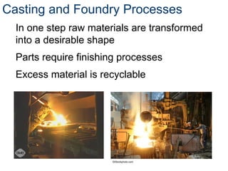
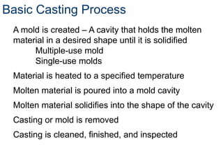
Basic Casting Process
Amold is created – A cavity that holds the molten
material in a desired shape until it is solidified
Multiple-use mold
Single-use molds
Material is heated to a specified temperature
Molten material is poured into a mold cavity
Molten material solidifies into the shape of the cavity
Casting or mold is removed
Casting is cleaned, finished, and inspected
14.
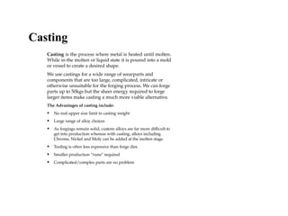
Casting is theprocess where metal is heated until molten.
While in the molten or liquid state it is poured into a mold
or vessel to create a desired shape.
We use castings for a wide range of wearparts and
components that are too large, complicated, intricate or
otherwise unsuitable for the forging process. We can forge
parts up to 50kgs but the sheer energy required to forge
larger items make casting a much more viable alternative.
The Advantages of casting include:
• No real upper size limit in casting weight
• Large range of alloy choices
• As forgings remain solid, custom alloys are far more difficult to
get into production whereas with casting, alloys including
Chrome, Nickel and Moly can be added at the molten stage.
• Tooling is often less expensive than forge dies
• Smaller production “runs” required
• Complicated/complex parts are no problem
Casting
15.
Casting
Investment Casting: isthe term applied to precision moulding using a metal die and ceramic coating in which
the chosen metal is injected. (Moulds are typically wax or foam)
Sand Casting: is considered the traditional method of casting. The various common methods of sand casting
revolve around the types of binders used to maintain mould strength (resist the molten metal).
The main points we look at when deciding between sand and investment casting are;
The size of the part
Investment casting is best suited for small parts up to a maximum of 80 kgs and 1.2 metres in length. Larger
parts create too much pressure and distortion of the walls of the mould. Larger castings are best made as a sand
cast.
Tolerances
Lower tolerances and a better surface finish can be achieved using the investment method.
Cost
As a general rule we can produce investment castings at a better price than sand castings. We only source
castings from those who make them better than everyone else. This means that our sand castings come from
countries where the costs of production tend to be higher than countries that produce high quality investment
castings, thus they are more expensive.
Casting Methods:
VIDEO
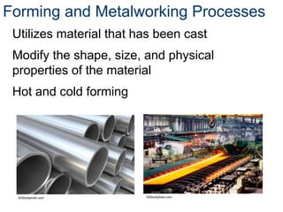
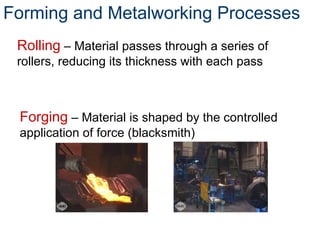
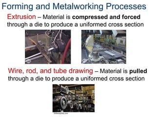
Forming and MetalworkingProcesses
Rolling – Material passes through a series of
rollers, reducing its thickness with each pass
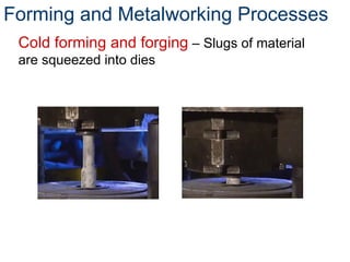
Forging – Material is shaped by the controlled
application of force (blacksmith)
CNC (Computerized NumericalControl)
The main purpose of a CNC program is to provide detailed instructions
necessary to machine a part (also called a workpiece) for a given machine
setup - with minimal human interaction.
All instructions to the control system must be written in a logical order and
in a specified format called the program structure.
The resulting CNC Program or a Part Program can be stored on various
media for the future and used repeatedly to achieve identical machining
results at any time.
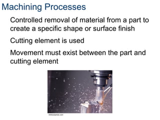
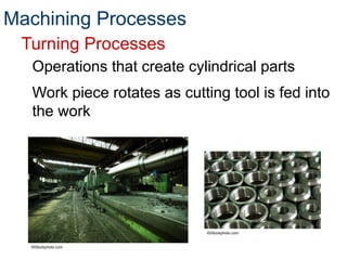
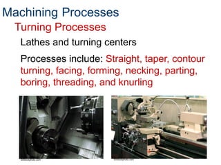
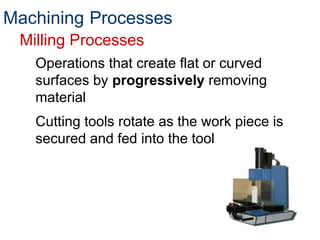
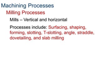
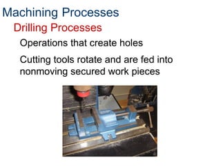
Machining
Milling Processes
Operations thatcreate flat or curved
surfaces by progressively removing
material
Cutting tools rotate as the work piece is
secured and fed into the tool
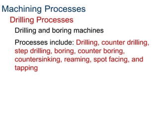
Machining Processes
25.
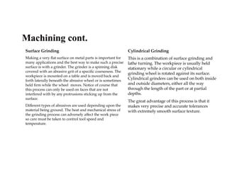
Surface Grinding
Making avery flat surface on metal parts is important for
many applications and the best way to make such a precise
surface is with a grinder. The grinder is a spinning disk
covered with an abrasive grit of a specific coarseness. The
workpiece is mounted on a table and is moved back and
forth laterally beneath the abrasive wheel or is sometimes
held firm while the wheel moves. Notice of course that
this process can only be used on faces that are not
interfered with by any protrusions sticking up from the
surface.
Different types of abrasives are used depending upon the
material being ground. The heat and mechanical stress of
the grinding process can adversely affect the work piece
so care must be taken to control tool speed and
temperature.
Cylindrical Grinding
This is a combination of surface grinding and
lathe turning. The workpiece is usually held
stationary while a circular or cylindrical
grinding wheel is rotated against its surface.
Cylindrical grinders can be used on both inside
and outside diameters, either all the way
through the length of the part or at partial
depths.
The great advantage of this process is that it
makes very precise and accurate tolerances
with extremely smooth surface texture.
Machining cont.
Surface Grinding
Making avery flat surface on metal parts is important for
many applications and the best way to make such a precise
surface is with a grinder. The grinder is a spinning disk
covered with an abrasive grit of a specific coarseness. The
workpiece is mounted on a table and is moved back and
forth laterally beneath the abrasive wheel or is sometimes
held firm while the wheel moves. Notice of course that
this process can only be used on faces that are not
interfered with by any protrusions sticking up from the
surface.
Different types of abrasives are used depending upon the
material being ground. The heat and mechanical stress of
the grinding process can adversely affect the work piece
so care must be taken to control tool speed and
temperature.
Cylindrical Grinding
This is a combination of surface grinding and
lathe turning. The workpiece is usually held
stationary while a circular or cylindrical
grinding wheel is rotated against its surface.
Cylindrical grinders can be used on both inside
and outside diameters, either all the way
through the length of the part or at partial
depths.
The great advantage of this process is that it
makes very precise and accurate tolerances
with extremely smooth surface texture.
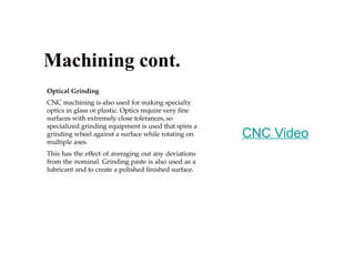
Machining cont.
Optical Grinding
CNC machiningis also used for making specialty
optics in glass or plastic. Optics require very fine
surfaces with extremely close tolerances, so
specialized grinding equipment is used that spins a
grinding wheel against a surface while rotating on
multiple axes.
This has the effect of averaging out any deviations
from the nominal. Grinding paste is also used as a
lubricant and to create a polished finished surface.
Machining cont.
CNC Video
31.
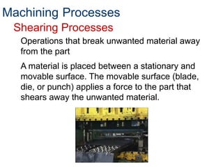
Shearing Processes
Operations thatbreak unwanted material away
from the part
A material is placed between a stationary and
movable surface. The movable surface (blade,
die, or punch) applies a force to the part that
shears away the unwanted material.
Machining Processes
32.
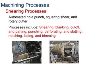
Automated hole punch,squaring shear, and
rotary cutter
Processes include: Shearing, blanking, cutoff,
and parting; punching, perforating, and slotting;
notching, lacing, and trimming
Shearing Processes
Machining Processes
33.
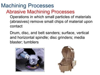
Abrasive Machining Processes
Operationsin which small particles of materials
(abrasives) remove small chips of material upon
contact
Drum, disc, and belt sanders; surface, vertical
and horizontal spindle; disc grinders; media
blaster; tumblers
Machining Processes
34.
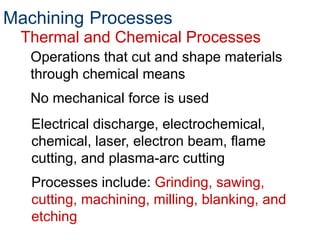
Thermal and ChemicalProcesses
Operations that cut and shape materials
through chemical means
No mechanical force is used
Machining Processes
Electrical discharge, electrochemical,
chemical, laser, electron beam, flame
cutting, and plasma-arc cutting
Processes include: Grinding, sawing,
cutting, machining, milling, blanking, and
etching
35.
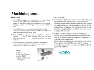
Solid Sink EDM
•A conductive electrode is placed close to the work piece
while bathed in a dielectric fluid. The electrode is
precisely shaped for the feature that it’s cutting. As the
electrode discharges, metal particles are forced off the
surface of the workpiece. The electrode itself does not
touch the workpiece but is sacrificial and may need to
be replaced frequently.
• EDM is used to make pockets, holes and square
features inside of hardened tool steels that would be
difficult, if not impossible, to make any other way. It’s
typically used on molds for
plastic injection and pressure die casting, rarely on the
finished piece itself. EDM is also used for making
textured surfaces or debossed (recessed) lettering and
logos on mold tools.
Machining cont.
Wire EDM
• Wire EDM uses copper wire as a conductor for a high-voltage
electric charge. Fresh wire is fed from a spool as the
conductor is steadily eroded during the cutting process. This
technique requires a pass through and can’t be used in a blind
hole.
• Wire EDM is used on thick, hardened tool steel to make
circular or semi-circular features that would be very difficult to
make with conventional cutting tools.
• Wire-cut EDM is typically used to cut plates as thick as
300mm and to make punches, tools, and dies from
hard metals that are difficult to machine with other
methods.
• Wire-cutting EDM is commonly used when low residual
stresses are desired, because it does not require high
cutting forces for removal of material.
Where:
1:Wire
2:Electrical Discharge
Erosion (EDM)
3: Electrical Potential
4: Workpiece
VIDEO
36.
Heat Treating Processes
Controlledheating and cooling of a material to
alter its properties while maintaining its shape
Properties include: Strength, toughness,
machinability, wear resistance, and corrosion
resistance
90% of heat treating is preformed on steel and
other ferrous metals
37.
Heat Treating Processes
Toaid in the manufacturing process, materials
can be treated to be weak and ductile and
then can be re-treated to provide high
strength.
Can also occur incidentally during the
manufacturing process
38.
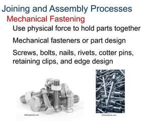
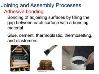
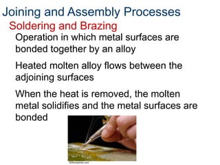
Joining and AssemblyProcesses
Can you think of a product with only one
part?
Most products consist of multiple parts that
are assembled to form a finished product.
Typical assembly processes include:
Mechanical fastening; soldering and
brazing, welding; adhesive bonding
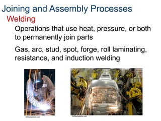
Welding
Welding is afabrication or sculptural process that joins
materials, usually metals or thermoplastics, by using high
heat to melt the parts together and allowing them to cool
causing fusion
• Welding is distinct from lower temperature metal-joining
techniques such as brazing and soldering, which do not
melt the base metal.
• In addition to melting the base metal, a filler material is
typically added to the joint to form a pool of molten
material (the weld pool) that cools to form a joint that,
based on weld configuration (butt, full penetration, fillet,
etc.), can be stronger than the base material (parent metal).
Pressure may also be used in conjunction with heat, or by
itself, to produce a weld. Welding also requires a form of
shield to protect the filler metals or melted metals from
being contaminated or oxidized.
Advantages:
Strong, stiff joint that does not lose preload or slip.
Inexpensive (if you have the staff and machines)
Joining and Assembly Processes
42.
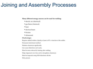
Many different energysources can be used for welding:
• electric arc (electrical)
• gas flame (chemical)
• laser
• electron beam
• friction
• ultrasound
Disadvantages:
Requires skilled welders. Quality of joint is 95% a function of the welder.
Permanent attachment method.
Weakens aluminum significantly.
Can cause distortions and cracks.
Must be stress relieved by heating after welding.
Helps alignment over time and re-strengthens aluminum.
Must be inspected using NDI oftentimes off-site.
Dirty process
Joining and Assembly Processes
43.
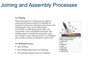
Arc Welding
These processesuse a welding power supply to
create and maintain an electric arc between an
electrode and the base material to melt metals at the
welding point. They can use either direct
current (DC) or alternating current (AC), and
consumable or non-consumable electrodes. The
welding region is sometimes protected by some
type of inert or semi-inert gas, known as a shielding
gas, and filler material is sometimes used as well.
Arc Welding Processes:
• Stick Welding
• MIG Welding (Metal Inert Gas Welding)
• TIG Welding (Tungsten Inert Gas Welding)
Joining and Assembly Processes
44.
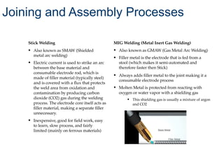
Stick Welding
• Alsoknown as SMAW (Shielded
metal arc welding)
• Electric current is used to strike an arc
between the base material and
consumable electrode rod, which is
made of filler material (typically steel)
and is covered with a flux that protects
the weld area from oxidation and
contamination by producing carbon
dioxide (CO2) gas during the welding
process. The electrode core itself acts as
filler material, making a separate filler
unnecessary.
• Inexpensive, good for field work, easy
to learn, slow process, and fairly
limited (mainly on ferrous materials)
MIG Welding (Metal Inert Gas Welding)
• Also known as GMAW (Gas Metal Arc Welding)
• Filler metal is the electrode that is fed from a
stool (which makes it semi-automated and
therefore faster then Stick)
• Always adds filler metal to the joint making it a
consumable electrode process
• Molten Metal is protected from reacting with
oxygen or water vapor with a shielding gas
• This shielding gas is usually a mixture of argon
and CO2
Joining and Assembly Processes
45.
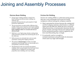
Electron Beam Welding
•Energy beam welding methods, namely laser
beam welding and electron beam welding, are
relatively new
processes that have become quite popular in high
production applications.
• The two processes are quite similar, differing most
notably in their source of power. Laser beam welding
employs a highly focused laser beam, while electron
beam welding is done in a vacuum and uses an
electron beam.
• Both have a very high energy density, making deep
weld penetration possible and minimizing the size of
the weld area.
• Both processes are extremely fast, and are easily
automated, making them highly productive.
• The primary disadvantages are their very high
equipment costs (though these are decreasing) and a
susceptibility to thermal cracking.
• Developments in this area include laser-hybrid
welding, which uses principles from both laser beam
welding and arc welding for even better weld
properties, laser cladding, and x-ray welding.
Friction Stir Welding
Friction stir welding (FSW) is a solid-state joining process
that uses a non-consumable tool to join two facing
workpieces without melting the workpiece material.
• Heat is generated by friction between the rotating tool
and the workpiece material, which leads to a softened
region near the FSW tool. While the tool is traversed
along the joint line, it mechanically intermixes the two
pieces of metal, and forges the hot and softened metal
by the mechanical pressure, which is applied by the
tool, much like joining clay, or dough.
• It is primarily used on wrought or
extruded aluminium and particularly for structures
which need very high weld strength.
Joining and Assembly Processes
46.
Welding Integrity
• Manydistinct factors influence the strength of
welds and the material around them,
including the welding method, the amount
and concentration of energy input, the
weldability of the base material, filler material,
and flux material, the design of the joint, and
the interactions between all these factors
• Types of welding defects include cracks,
distortion, gas inclusions (porosity), non-
metallic inclusions, lack of fusion, incomplete
penetration, lamellar tearing, and
undercutting
• Methods such as visual
inspection, radiography, ultrasonic testing,
phased- array ultrasonics, dye penetrant
inspection, magnetic
particle inspection, or industrial computed
tomography can help with detection and
analysis of certain defects
Joining and Assembly Processes
47.
Brazing
Brazing is ametal-joining process in which two or
more metal items are joined together by melting and
flowing a filler metal into the joint, the filler metal
having a lower melting point than the adjoining
metal.
• Brazing differs from welding in that it does not
involve melting the work pieces and from
soldering in using higher temperatures for a
similar process, while also requiring much more
closely fitted parts than when soldering
• A major advantage of brazing is the ability to
join the same or different metals with
considerable strength.
• In most cases, joint clearances of 0.03 to 0.08
mm (0.0012 to 0.0031 in) are recommended for
the best capillary action and joint strength.
However, in some brazing operations it is not
uncommon to have joint clearances around 0.6
mm (0.024 in)
• Flux is a chemical cleaning agent, flowing agent, or purifying
agent. Unless brazing operations are contained within
an inert or reducing atmosphere environment (i.e. a vacuum
furnace), a flux such as borax is required to prevent oxides
from forming while the metal is heated. The flux also serves the
purpose of cleaning any contamination left on the brazing
surfaces. Flux can be applied in any number of forms including
flux paste, liquid, powder or pre-made brazing pastes that
combine flux with filler metal powder.
• Braze alloy is generally available as rod, ribbon, powder, paste,
cream, wire and preforms (such as stamped washers)
• As brazing work requires high temperatures, oxidation of the
metal surface occurs in an oxygen-containing atmosphere. This
may necessitate the use of an atmospheric environment other
than air.
Joining and Assembly Processes
48.
Brazing
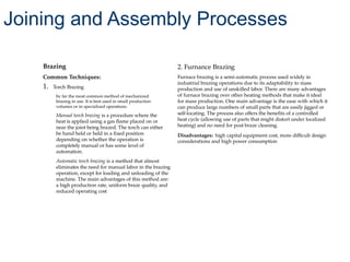
Common Techniques:
1. TorchBrazing
by far the most common method of mechanized
brazing in use. It is best used in small production
volumes or in specialized operations
Manual torch brazing is a procedure where the
heat is applied using a gas flame placed on or
near the joint being brazed. The torch can either
be hand held or held in a fixed position
depending on whether the operation is
completely manual or has some level of
automation.
Automatic torch brazing is a method that almost
eliminates the need for manual labor in the brazing
operation, except for loading and unloading of the
machine. The main advantages of this method are:
a high production rate, uniform braze quality, and
reduced operating cost
2. Furnance Brazing
Furnace brazing is a semi-automatic process used widely in
industrial brazing operations due to its adaptability to mass
production and use of unskilled labor. There are many advantages
of furnace brazing over other heating methods that make it ideal
for mass production. One main advantage is the ease with which it
can produce large numbers of small parts that are easily jigged or
self-locating. The process also offers the benefits of a controlled
heat cycle (allowing use of parts that might distort under localized
heating) and no need for post braze cleaning.
Disadvantages: high capital equipment cost, more difficult design
considerations and high power consumption
Joining and Assembly Processes
49.
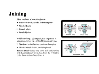
Main methods ofattaching joints:
• Fasteners (Bolts, Rivets, and shear pins)
• Welded Joints
• Brazed Joints
• Bonded Joints
When selecting a type of joint, it is important to
understand what type of load they are carrying:
• Tension – Not adhesives, rivets, or shear pins
• Shear - bolted, riveted, or shear pinned
Tension-Shear -Bolted-only joints that carry tensile,
and shear loads rely on friction from the preload to
resist shear motion. Sometimes at
Joining
50.
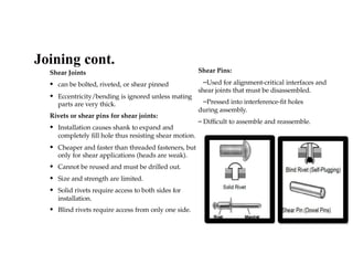
Shear Joints
• canbe bolted, riveted, or shear pinned
• Eccentricity/bending is ignored unless mating
parts are very thick.
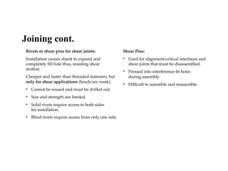
Rivets or shear pins for shear joints:
• Installation causes shank to expand and
completely fill hole thus resisting shear motion.
• Cheaper and faster than threaded fasteners, but
only for shear applications (heads are weak).
• Cannot be reused and must be drilled out.
• Size and strength are limited.
• Solid rivets require access to both sides for
installation.
• Blind rivets require access from only one side.
Shear Pins:
–Used for alignment-critical interfaces and
shear joints that must be disassembled.
–Pressed into interference-fit holes
during assembly.
– Difficult to assemble and reassemble.
Joining cont.
51.
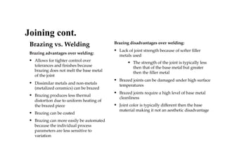
Brazing vs. Welding
Brazingadvantages over welding:
• Allows for tighter control over
tolerances and finishes because
brazing does not melt the base metal
of the joint
• Dissimilar metals and non-metals
(metalized ceramics) can be brazed
• Brazing produces less thermal
distortion due to uniform heating of
the brazed piece
• Brazing can be coated
• Brazing can more easily be automated
because the individual process
parameters are less sensitive to
variation
Brazing disadvantages over welding:
• Lack of joint strength because of softer filler
metals used
• The strength of the joint is typically less
then that of the base metal but greater
then the filler metal
• Brazed joints can be damaged under high surface
temperatures
• Brazed joints require a high level of base metal
cleanliness
• Joint color is typically different then the base
material making it not an aesthetic disadvantage
Joining cont.
52.
Rivets or shearpins for shear joints:
Installation causes shank to expand and
completely fill hole thus, resisting shear
motion.
Cheaper and faster than threaded fasteners, but
only for shear applications (heads are weak).
• Cannot be reused and must be drilled out.
• Size and strength are limited.
• Solid rivets require access to both sides
for installation.
• Blind rivets require access from only one side.
Shear Pins:
• Used for alignment-critical interfaces and
shear joints that must be disassembled.
• Pressed into interference-fit holes
during assembly.
• Difficult to assemble and reassemble.
Joining cont.
53.
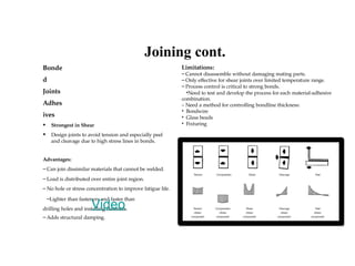
Bonde
d
Joints
Adhes
ives
• Strongest inShear
• Design joints to avoid tension and especially peel
and cleavage due to high stress lines in bonds.
Advantages:
– Can join dissimilar materials that cannot be welded.
– Load is distributed over entire joint region.
– No hole or stress concentration to improve fatigue life.
–Lighter than fasteners and faster than
drilling holes and installing fasteners.
–Adds structural damping.
Limitations:
– Cannot disassemble without damaging mating parts.
– Only effective for shear joints over limited temperature range.
– Process control is critical to strong bonds.
•Need to test and develop the process for each material-adhesive
combination.
– Need a method for controlling bondline thickness:
• Bondwire
• Glass beads
• Fixturing
Joining cont.
Video
54.
Fasteners
• Bolt isintended to be used with a nut. Torque
applied to the nut.
• Screw is meant to go into a threaded hole.
Torque applied to the head
• Example Specs:
• National Aeronautical Standard (NAS)
• Mil-Spec (MS)
• Typical Materials: A286 (160 ksi), Stainless Steel
Threaded Inserts:
• Used in aluminum parts instead of just a tapped hole.
• Reduces chance of galling material – dissimilar metals.
• Highly recommended if fasteners will be removed and
reinstalled many times.
• Insurance for your hardware
Joining cont.
55.
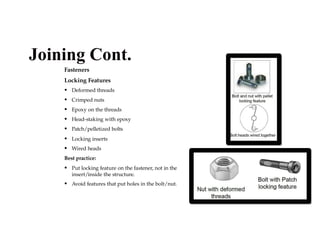
Fasteners
Locking Features
• Deformedthreads
• Crimped nuts
• Epoxy on the threads
• Head-staking with epoxy
• Patch/pelletized bolts
• Locking inserts
• Wired heads
Best practice:
• Put locking feature on the fastener, not in the
insert/inside the structure.
• Avoid features that put holes in the bolt/nut.
Joining Cont.
Rapid Prototyping
Additive process
Partsare produced directly from software
applications
Common rapid prototyping systems include:
stereolithography (SLA), selective laser
sintering (SLS), fused deposition modeling
(FDM), laminated object manufacturing
(LOM), digital light processing (DLP)
59.
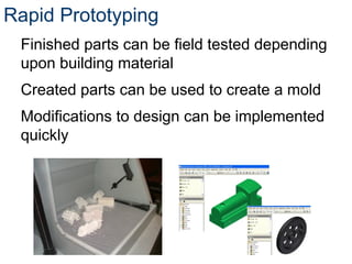
Rapid Prototyping
Finished partscan be field tested depending
upon building material
Created parts can be used to create a mold
Modifications to design can be implemented
quickly
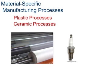
Plastics Manufacturing Processes
Arotating screw forces plastic through a
heating chamber and then through a
heated die
Produces long plastic parts with uniform
cross sections
Extrusio
n
63.
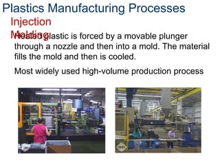
Heated plastic isforced by a movable plunger
through a nozzle and then into a mold. The material
fills the mold and then is cooled.
Most widely used high-volume production process
Plastics Manufacturing Processes
Injection
Molding
64.
Plastic is meltedand poured into a mold –
No pressure or fillers are required.
Plastics Manufacturing Processes
Castin
g
A closed mold is filled with a
predetermined amount of plastic. The
mold is heated, rotated, and then cooled
to create a hollow plastic object with
uniform wall thickness.
Rotational
Molding
65.
Plastics Manufacturing Processes
Asolid bottom hollow tube is placed
between two mold halves and heated.
The heated tube is then expanded into
the sides of the mold with compressed
air.
Blow
Molding
66.
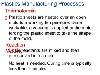
Plastics Manufacturing Processes
Liquidreactants are mixed and then
pressurized into a mold.
No heat is needed. Curing time is typically
less than 1 minute.
Reaction
Molding
Plastic sheets are heated over an open
mold to a working temperature. Once
workable, a vacuum is applied to the mold,
forcing the plastic sheet to take the shape
of the mold.
Thermoformin
g
67.
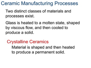
Ceramic Manufacturing Processes
Twodistinct classes of materials and
processes exist.
Glass is heated to a molten state, shaped
by viscous flow, and then cooled to
produce a solid.
Crystalline Ceramics
Material is shaped and then heated
to produce a permanent solid.
#12 Society of Manufacturing Engineers (Producer). (2010). Casting. Available from the Society of Manufacturing Engineers, One SME Drive: Dearborn, Michigan 48121.


![[DSC Europe 25] Paula Garcia Esteban -Building the Future: The Role of Data S...](https://cdn.slidesharecdn.com/ss_thumbnails/9ld1r1bsqpwve8qfvphy-paula-garcia-esteban-building-the-future-260122103838-4171f5cb-thumbnail.jpg?width=640&height=640&fit=bounds)


![[DSC Europe 25] Marcos Heidemann - Beyond the Hype: Making AI Coding Assistan...](https://cdn.slidesharecdn.com/ss_thumbnails/eexkhvldrjsopspdjbur-marcos-heidemann-beyond-the-hype-getting-real-value-out-of-ai-assisted-coding-260121115910-7e9d41ec-thumbnail.jpg?width=640&height=640&fit=bounds)


![[DSC Europe 25] Tali Fulman - Guild Meetings, Then What? Building Data Commun...](https://cdn.slidesharecdn.com/ss_thumbnails/fgohhi33rwmhqdowdj5k-tali-fulman-guild-meetings-then-what-building-data-communities-that-actually-ch-260120105855-528492c3-thumbnail.jpg?width=640&height=640&fit=bounds)

![[DSC Europe 25] Dubravko Culibrk - Deep Learning for Mammography.pptx](https://cdn.slidesharecdn.com/ss_thumbnails/yiscimuktacgqoiu4dkp-deep-learning-for-mammography-260119121559-aad59182-thumbnail.jpg?width=640&height=640&fit=bounds)

![[DSC Europe 25] Milos Belcevic - Product Professional's Journey to Full-Stack...](https://cdn.slidesharecdn.com/ss_thumbnails/1zovd6fgsycdg4wvgvls-milos-belcevic-product-professionals-journey-to-full-stack-product-developer-260123083019-d993120d-thumbnail.jpg?width=640&height=640&fit=bounds)

![[DSC Europe 25] Laila Kakar - Leveraging AI for Strategic Excellence: Enhanci...](https://cdn.slidesharecdn.com/ss_thumbnails/eykmhrtsqmaaftwkexh7-dsc-lailakakar-1-260119101520-5f3b5616-thumbnail.jpg?width=640&height=640&fit=bounds)


![[DSC Europe 25] Andrzej Kowalczyk - AI - how to start small and grow in the f...](https://cdn.slidesharecdn.com/ss_thumbnails/oy1zmo94qv6vpcqjvno2-andrzej-kowalczyk-ai-how-to-start-small-and-grow-in-the-future-1-260119121559-cf093b23-thumbnail.jpg?width=640&height=640&fit=bounds)


