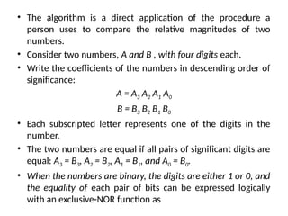
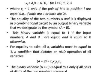
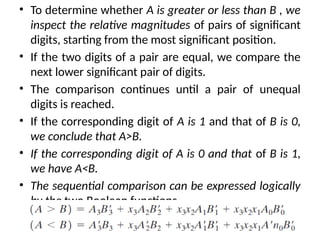
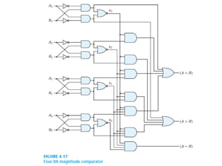
A magnitude comparator is a combinational circuit that compares two numbers and determines their relative magnitudes using binary variables for less than, equal, or greater than conditions. The circuit utilizes algorithms and logical functions to organize comparisons starting from the most significant digit, simplifying the complexity inherent in truth tables. The document outlines the design process for building a four-bit comparator and suggests an approach for larger binary numbers.