Downloaded 30 times


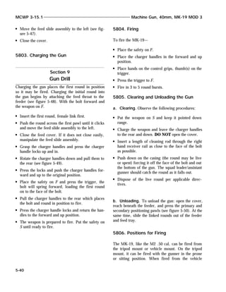
![this, he must rotate the windage knob to move the
peep sight in the direction of the desired change (ro-
tate windage knob toward the muzzle [counterclock-
wise] to move the strike of the round to the right;
rotate the windage knob toward the buttstock [clock-
wise] to move the strike of the round to the left).
One click in either direction moves the strike of the
round 1/2 cm at 10 meters.
For example, if the automatic rifleman sees that the
center of the shot group is 2 cm (two black aiming
pasters) to the left of the aiming point, he adjusts the
point of impact four clicks in the direction of the
aiming point (to the right) by rotating the windage
knob toward the muzzle.
(5) Elevation correction. Before making elevation
adjustments, the range knob must be at its highest
setting. If the center of the shot group is above or
below the aiming point, the automatic rifleman ro-
tates the peep sight clockwise to lower the strike of
the round or rotates the peep sight counterclockwise
to raise the strike of the round. One 180-degree turn
in either direction moves the strike of the round 1/2
cm at 10 meters.
(6) Confirmation. The automatic rifleman fires an-
other three-shot group (loaded singly) after making
his corrections for windage and elevation. If the cen-
ter of the group is still off the aiming point, he ad-
justs further until the group is centered on the point
of aim.
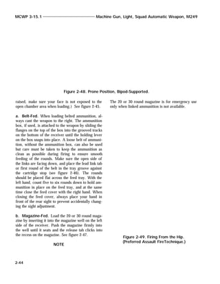
(7) Recording. There is no reason to record the
10-meter zero, because it applies only to firing at the
10-meter basic machine gun target.
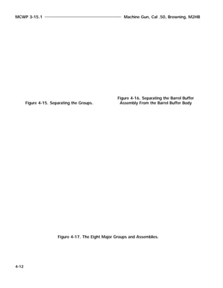
e. Field Zeroing. Automatic riflemen must know
how to zero the SAW at distance. He should select a
known distance target between 300 and 700 meters.
It is difficult to determine fully where the center of
the beaten zone is in relation to the target as range
increases. Therefore, the 300-meter target on the
transition range is recommended because of the ease
of determining adjustments.
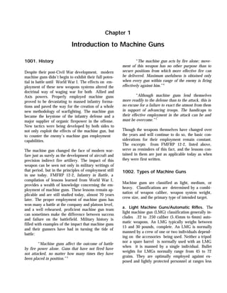
(1) Set the sights. The automatic rifleman uses the
same procedures as for 10-meter zeroing are used
Machine Guns and Machine Gun Gunnery MCWP 3-15.1
2-53
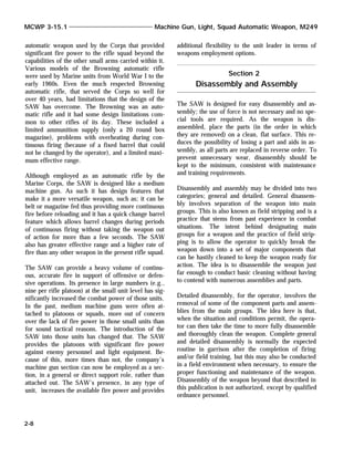
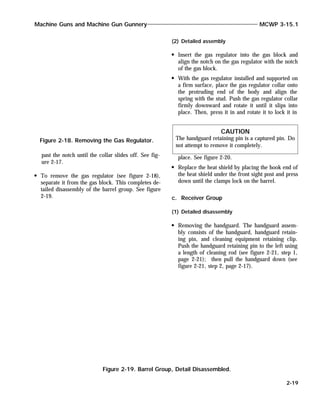
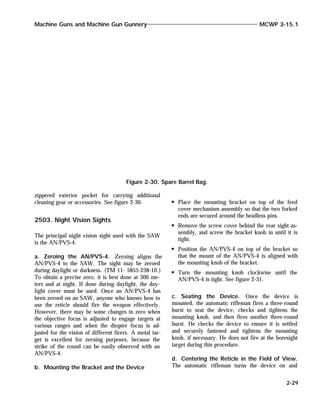
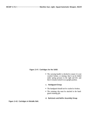
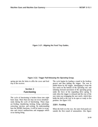
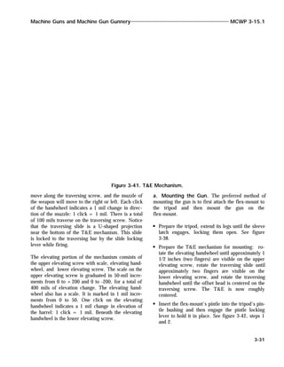
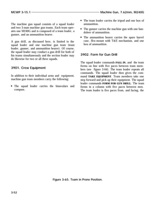
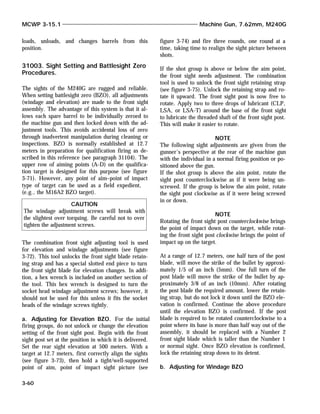
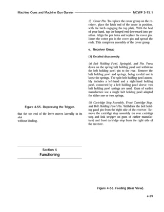
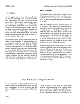
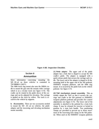
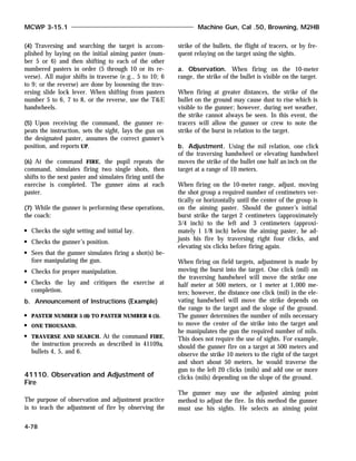
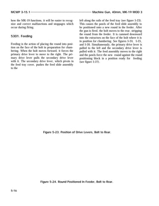
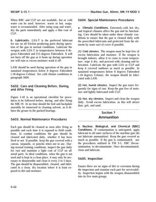
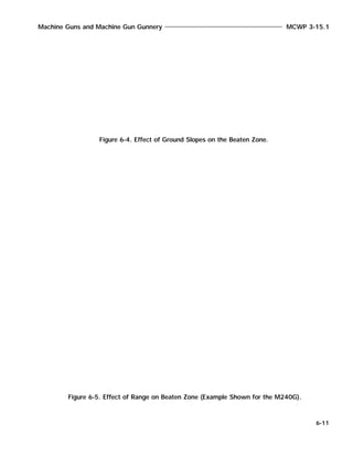
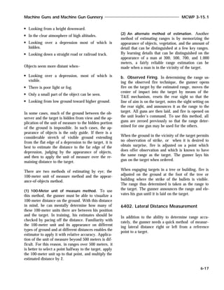
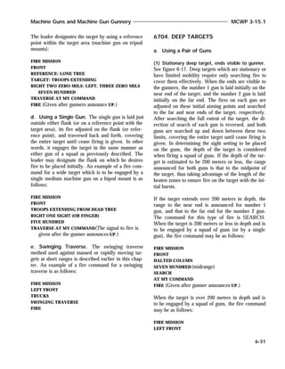
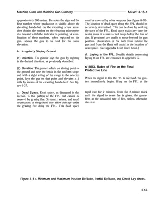
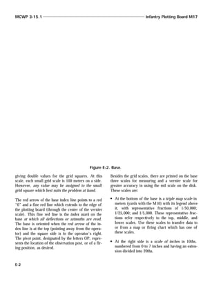
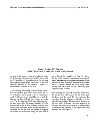
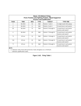
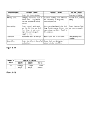
Figure 2-60. Firing Table I.](https://image.slidesharecdn.com/mcwp3-15-1-160404010440/85/Machine-Gun-and-Machine-Gunnery-62-320.jpg)


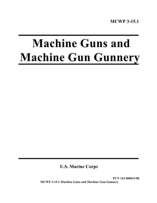
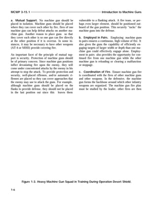
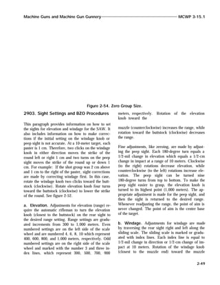
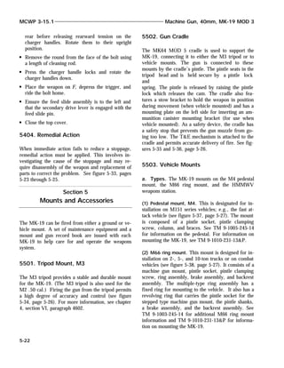
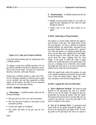
![5403. Immediate Action
Immediate action is that action taken by the
gunner/crew to reduce the stoppage, without investi-
gating the cause, and quickly return the gun to
action.
a. During Peacetime and Training
Clear the area of personnel.
Wait 10 seconds.
Pull bolt to the rear. (Catch the round as it is
ejected.)
Push charger handles forward and up.
Attempt to fire.
If nothing happens:
Put gun on S.
Wait 10 seconds.
Pull bolt to the rear. (Catch round as it is
ejected.)
Open the cover, unload, and clear the weapon.
b. During Extreme Combat Situations.
Press charger handle locks and rotate charger han-
dles down.
Pull and lock the bolt to the rear.
Push the charger handles forward and up to their
locked position.
Relay the gun on target and attempt to fire.
c. Subsequent Action. Two potentially serious
stoppages may occur with the MK-19 that require
different procedures from those described above.
(1) Bore Obstruction. This means that part of the
previous round may be lodged in the barrel and
could possibly prevent the next warhead from pass-
ing safely through it. The gunner/crew should be
alert for a muffled report from the gun when it fires,
smoke and debris from the bottom of the receiver,
and/or the failure of the warhead to leave the muz-
zle. The safety procedures are as follows:
Cease fire immediately.
Place the weapon on S.
Clear the area around the gun of personnel and
ammunition.
Notify safety, explosive ordnance disposal, and
ordnance personnel.
(2) Jammed Bolt. The bolt may jam as the gunner
is attempting to pull it to the rear. He will not be
able to pull and lock it to the rear or release rear-
ward tension and ride it forward.
Put the gun on S.
Press the charger handle locks and rotate the
charger handles down.
Pull the charger handles to the rear as far as pos-
sible and maintain rearward pressure on the han-
dles while the squad leader/assistant gunner lifts
the top cover.
Pull the charger handles to the rear until the bolt
locks to the rear. Ensure the bolt will stay to the
Machine Guns and Machine Gun Gunnery MCWP 3-15.1
5-21
WARNING
If immediate action of a stoppage (bolt forward) re-
sults in the extraction of a spent cartridge, the crew
will initiate subsequent action for a suspected ob-
struction in the barrel before attempting to fire again.
(See paragraph 5403C[1]).
WARNING
Do not open the top cover This could allow the bolt
to spring forward suddenly with a round on the face
of the bolt. If that round fires while the cover is open,
serious injury to personnel and damage to equipment
could occur. The following safety procedure should
be used:](https://image.slidesharecdn.com/mcwp3-15-1-160404010440/85/Machine-Gun-and-Machine-Gunnery-225-320.jpg)


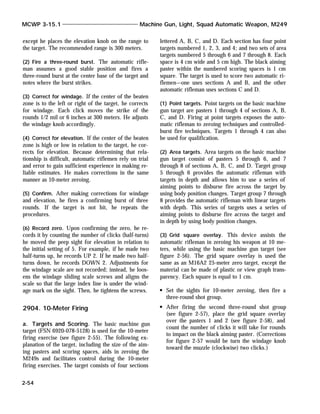
![FIRE MISSION
RIGHT FRONT
TROOPS EXTENDING FROM BLACK STUMP - RIGHT
TO LONE
PINE
SEVEN HUNDRED(midrange)
TRAVERSE AND SEARCH
AT MY SIGNAL
(Signal to fire given after gunners announce UP.)
When the target measures 100 mils or less in width,
is 200 meters or less in depth, and is to be engaged
by a section (minus) of four guns:
SQUAD 1, SQUAD 2
FIRE MISSION
FRONT
TROOPS TO THE RIGHT OF RED BANK
SEVEN HUNDRED(midrange)
TRAVERSE AND SEARCH
AT MY SIGNAL
(Signal to fire given after gunners announce UP.)
When the target is wide enough to necessitate subdi-
viding, is over 200 meters in depth, and is to be en-
gaged by a squad of guns or by a section (minus) of
four guns:
FIRE MISSION
FRONT
TROOPS EXTENDING FROM TRUCK - RIGHT TO
BRIDGE
NUMBER 1 (and 3 if section [minus] of four guns is
engaging the target),
SEVEN HUNDRED
NUMBER 2 (and 4 if section [minus] of four guns is
engaging the target),
ONE THOUSAND
NUMBER 1 (and 3),
RIGHT HALF NUMBER 2 (and 4),
LEFT HALF TRAVERSE AND SEARCH
AT MY SIGNAL
(Signal to fire given after gunners announce UP.)
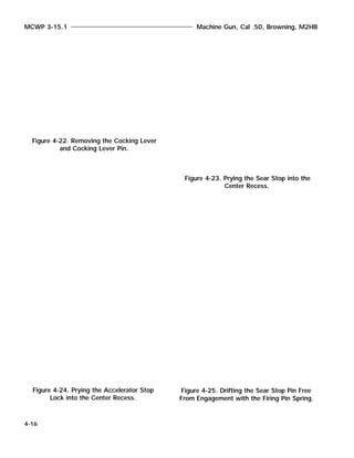
6706. Area Targets
Targets which cannot be covered by either traversing
fire or searching fire alone, or by combined
traversing and searching fire (as in the case of
oblique targets) are called area targets. The area
which can be covered effectively by a squad of guns
or by a section (minus) of four guns is small because
of the time and ammunition required for this type.
a. Using a Squad of Guns
(1) Flanks visible. When the flanks of the target are
visible to the gunners, the guns are laid just outside
their corresponding flanks. Each gun then fires trav-
ersing fire across its assigned portion of the target,
changes elevation the total amount prescribed in the
initial fire command, traverses back to the flank
from which traversing fire was started, and ceases
firing. A typical manipulation element of the fire
command would be TRAVERSE, SEARCH UP 4 (MILS)
or SEARCH UP 100 (METERS). Further firing over the
area is on the leader’s orders.
Machine Guns and Machine Gun Gunnery MCWP 3-15.1
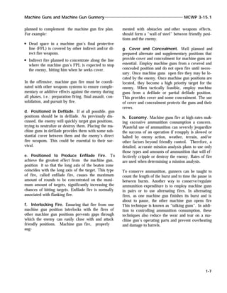
6-35
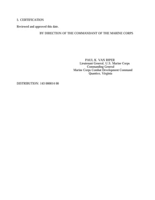
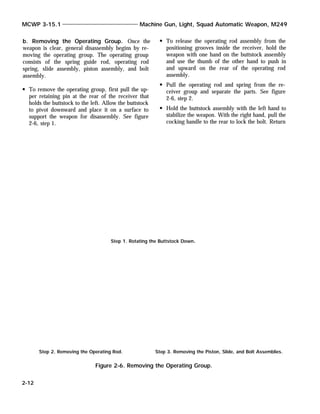
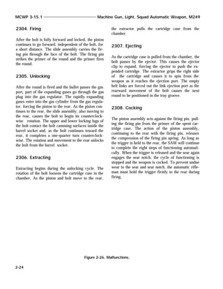
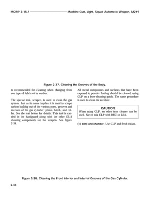
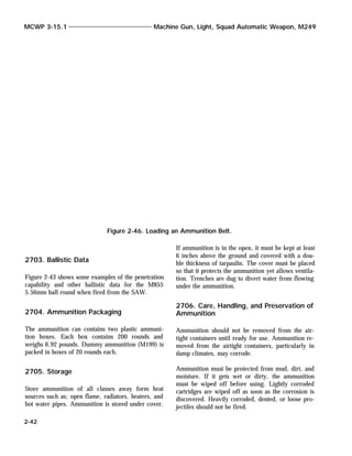
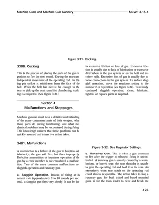
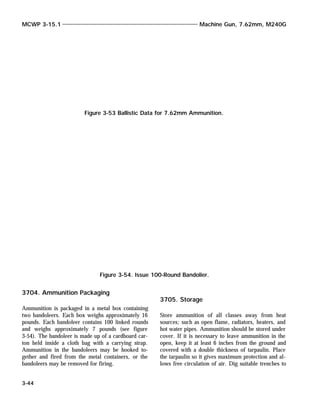
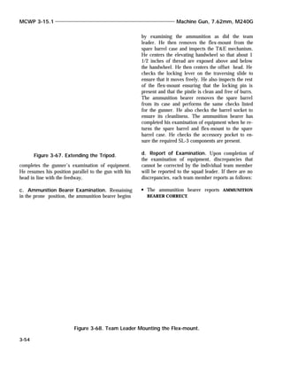
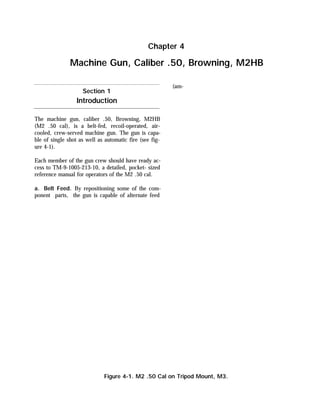
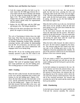
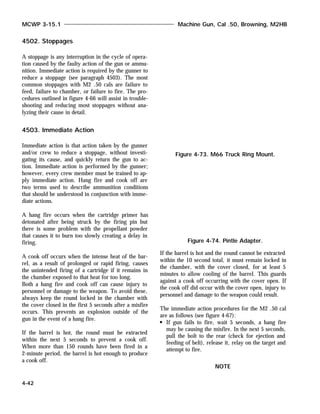
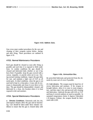
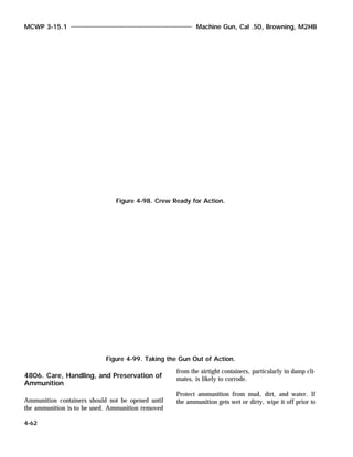
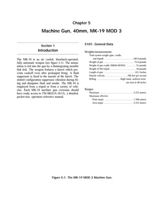
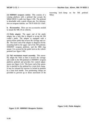
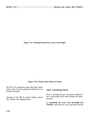
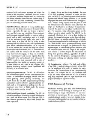
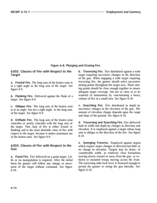
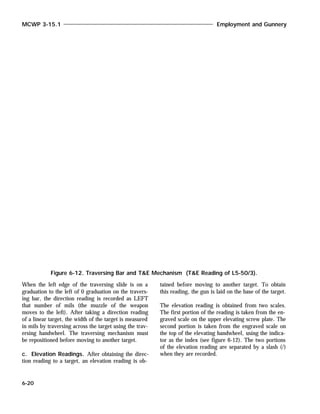
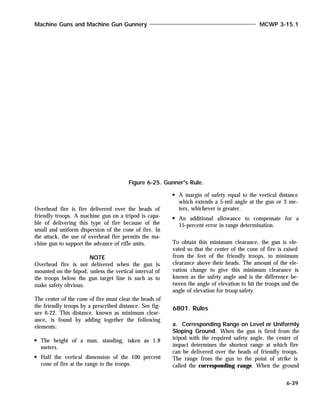
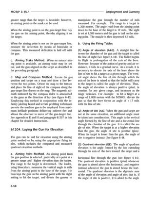
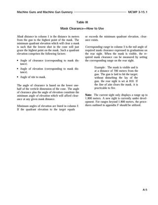
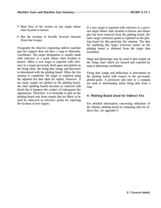
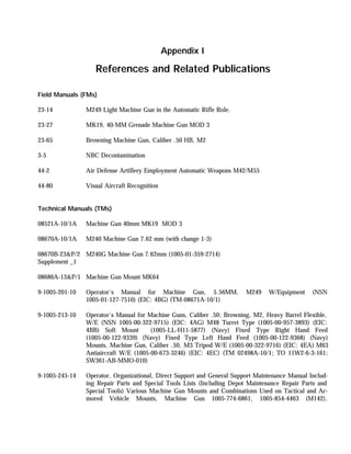
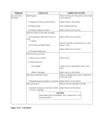
Figure 6-21. Moving Target Aiming Points.](https://image.slidesharecdn.com/mcwp3-15-1-160404010440/85/Machine-Gun-and-Machine-Gunnery-282-320.jpg)


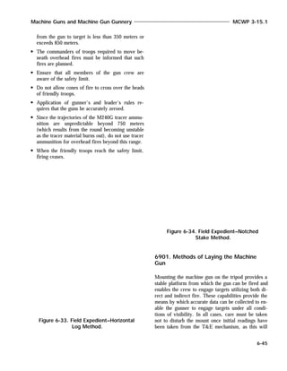


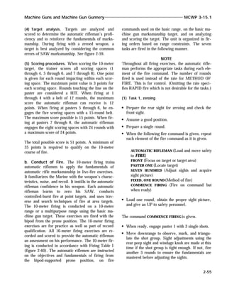
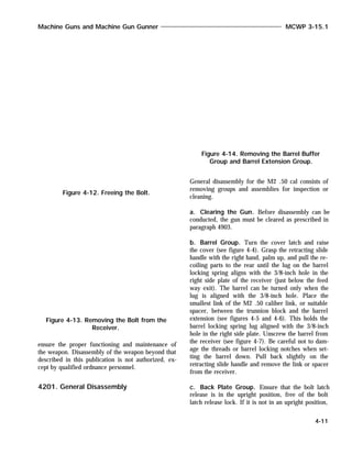
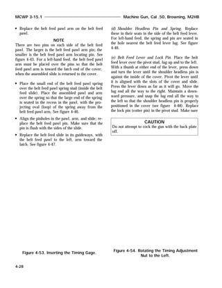
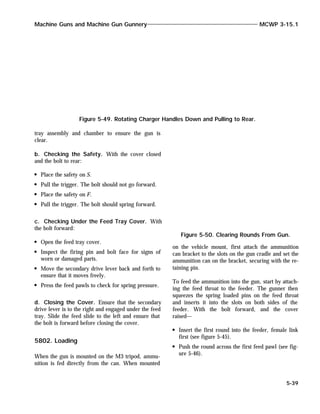
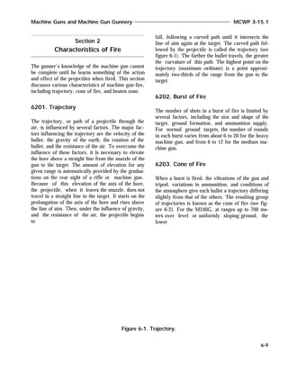
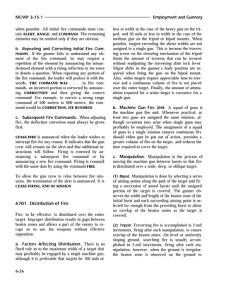
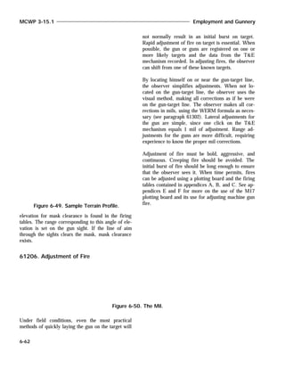
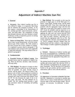
![of elevation; if the angle of site is negative, it is sub-
tracted from the angle of elevation.
(a) Quadrant of Elevation When Gun and Target are
on the Same Horizontal Plane. The target is a range
of 1,000 meters and on the same horizontal plane as
the gun. Therefore, elevate the gun to form an angle
of 16 mils with the line of site (since +16 mils is
the angle of elevation for a range of 1,000 meters).
(See fig. 6-44 [1].) The angle of sight is 0, because
the line of site coincides with the horizontal; there-
fore, the quadrant elevation is +16 mils (the alge-
braic sum of the angle of elevation [+16] and the
angle of site [0]).
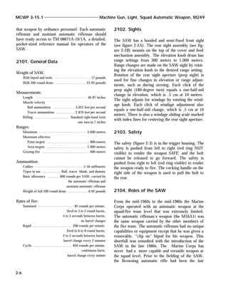
(b) Quadrant of Elevation When the Target is
Higher Than the Gun. The target is at a range of
1,000 meters and at greater elevation than the gun
Machine Guns and Machine Gun Gunnery MCWP 3-15.1
6-59
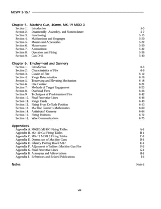
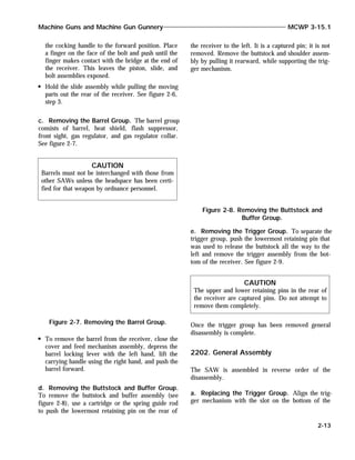
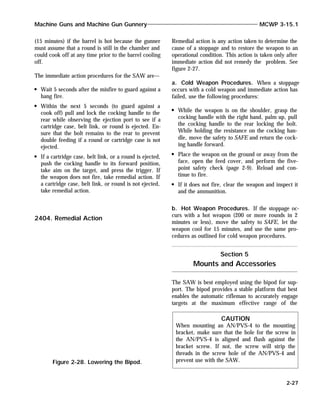
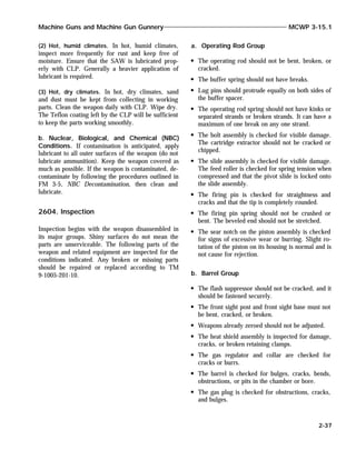
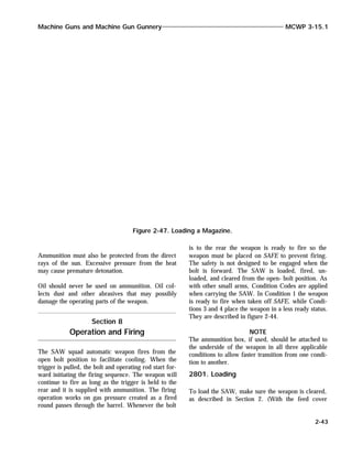
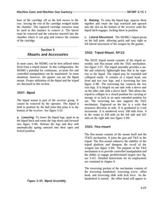
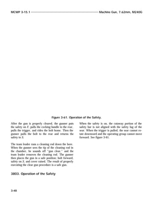
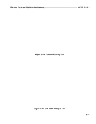
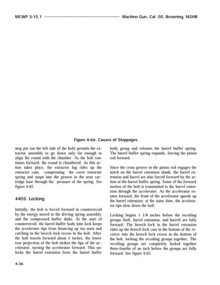
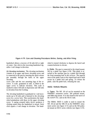
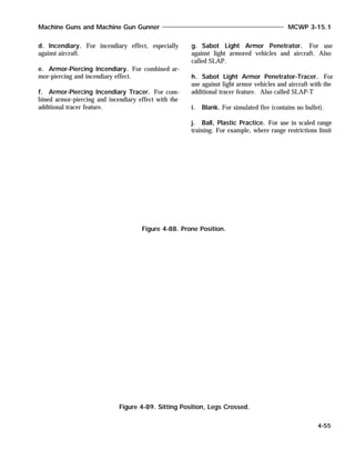
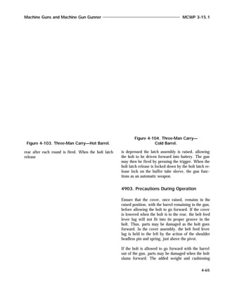
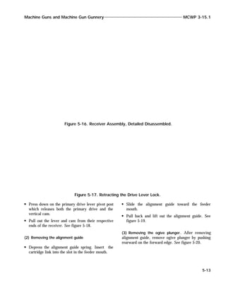
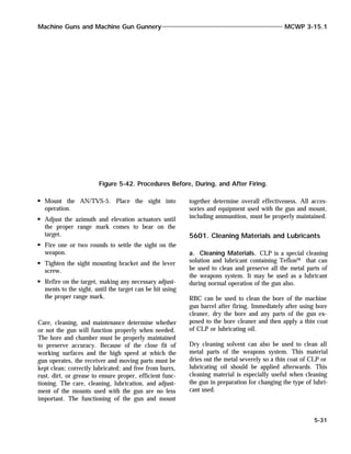
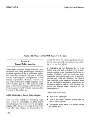
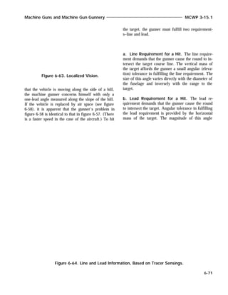
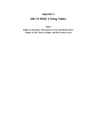
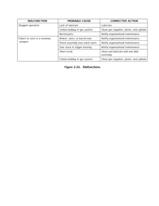
Figure 6-46. Profile Line (Map Contour Interval is 10 Feet).
Figure 6-45. Profile Example.](https://image.slidesharecdn.com/mcwp3-15-1-160404010440/85/Machine-Gun-and-Machine-Gunnery-306-320.jpg)
![(see figure 6-44 [2]). To hit the target, fire the gun
at an angle equal to the angle of elevation for the
range (+ 16 mils) plus the angle of site. The angle
of site is +5 mils; therefore, lay the gun with a
quadrant elevation of +16 and +5, or a total of
+21 mils.
(c) Quadrant of Elevation When the Target is Lower
Than the Gun. The target is at a range of 1,000 me-
ters but at a lesser elevation than the gun (see figure
6-44 [3]). To hit the target, fire the gun at an angle
equal to the angle of elevation for the range (+ 16
mils) minus the angle of site. The angle of site is -5
mils; therefore, lay the gun with a quadrant eleva-
tion of +16 and -5, or a total of +11 mils. Figure
6-44 illustrates a case where the target is at a range
of 1,000 meters and the angle of site is -20 mils.
Since the angle of elevation is +16 mils, the quad-
rant elevation is the combination of +16 mils and
-20, or an algebraic sum of -4 mils. Negative or mi-
nus angles of quadrant elevation are not common,
but may be encountered on certain types of terrain.
c. Computed Quadrant Elevation Method
(Heavy Gun)
Determine the range to the target by the most accu-
rate means available and obtain the corresponding
angle of elevation from the firing tables. Determine
the angle of site by use of the aiming circle or the
binocular. When the binocular is used, determine the
angle of site by measuring in mils the vertical inter-
val between the target and the estimated horizontal.
In estimating the horizontal, assume the distant hori-
zon to be at an angle of site of zero, or at the same
elevation as the gun position. Determine the angle of
quadrant elevation by algebraically adding this data.
Place the quadrant elevation on the gun with the M2
compass.
d. Measured Quadrant Elevation Method
(Heavy Gun)
NOTE
MCWP 3-15.1 Employment and Gunnery
6-60
Figure 6-47. Marking of Elevation.](https://image.slidesharecdn.com/mcwp3-15-1-160404010440/85/Machine-Gun-and-Machine-Gunnery-307-320.jpg)


This document provides an overview of machine gun types used by the U.S. Marine Corps. It describes light machine guns such as the M249, medium machine guns such as the M240G, and heavy machine guns such as the M2 .50 caliber. It discusses key characteristics of each type including caliber, weight, crew size, and intended targets. The document emphasizes that while weapons have changed, fundamental principles of machine gun employment remain constant based on lessons from World War I.


![Combat load presentation[1]](https://cdn.slidesharecdn.com/ss_thumbnails/combatloadpresentation1-140218173632-phpapp02-thumbnail.jpg?width=640&height=640&fit=bounds)


![Field%20 Artillery%20 Presentation[1]](https://cdn.slidesharecdn.com/ss_thumbnails/field20artillery20presentation1-091204102336-phpapp02-thumbnail.jpg?width=640&height=640&fit=bounds)