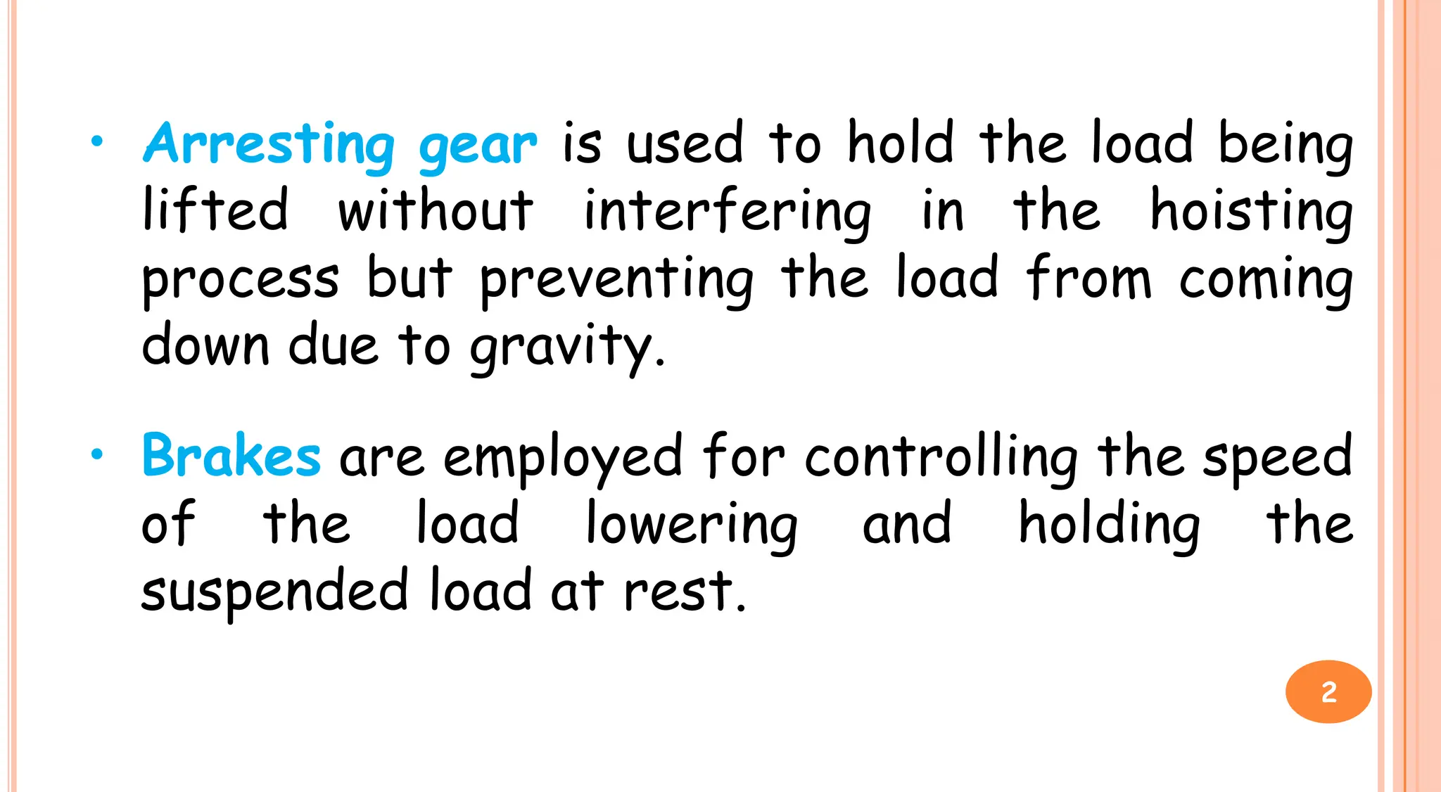
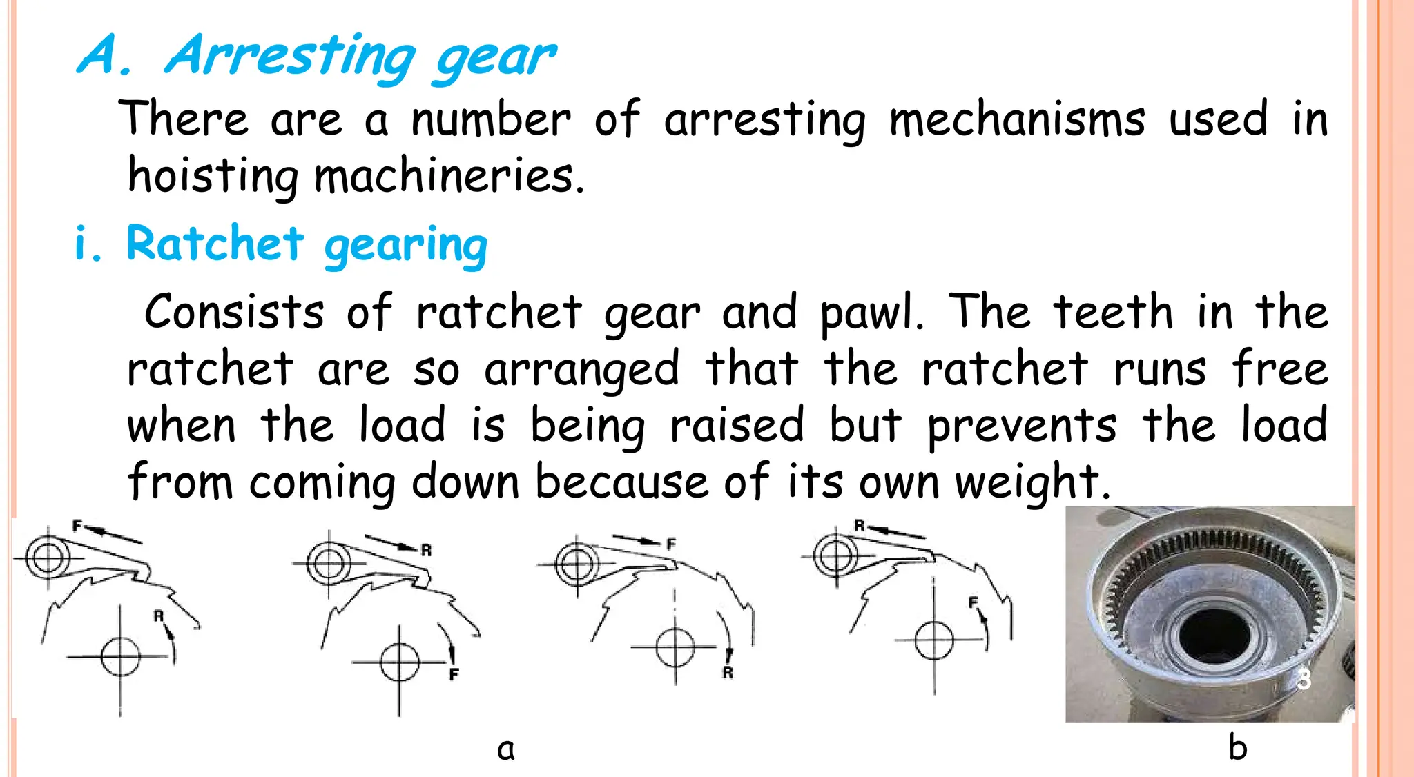
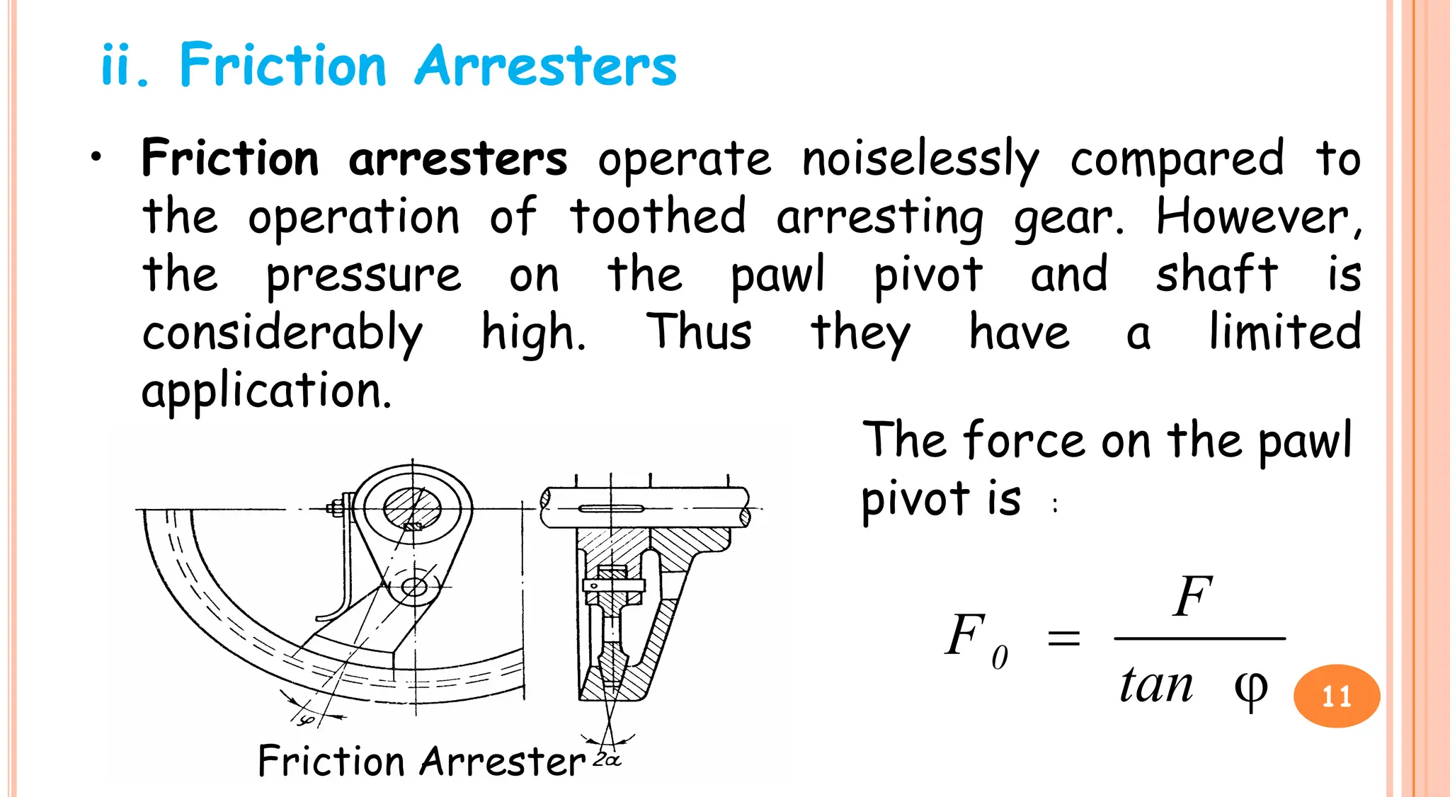
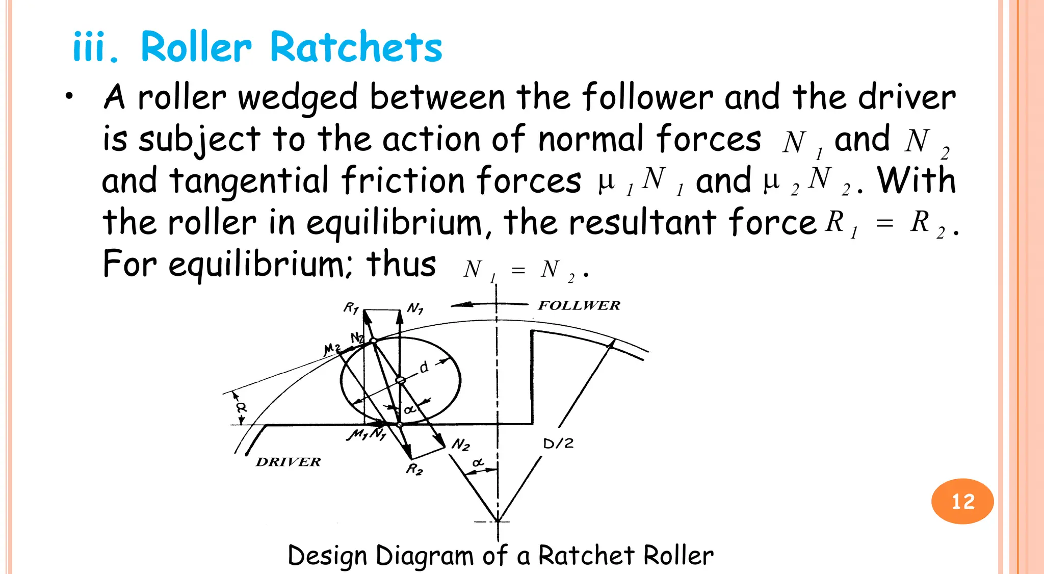
1. Arresting gear is used to hold loads being lifted without interfering with hoisting but preventing downward motion from gravity. Common arresting mechanisms include ratchet gearing and friction arresters.
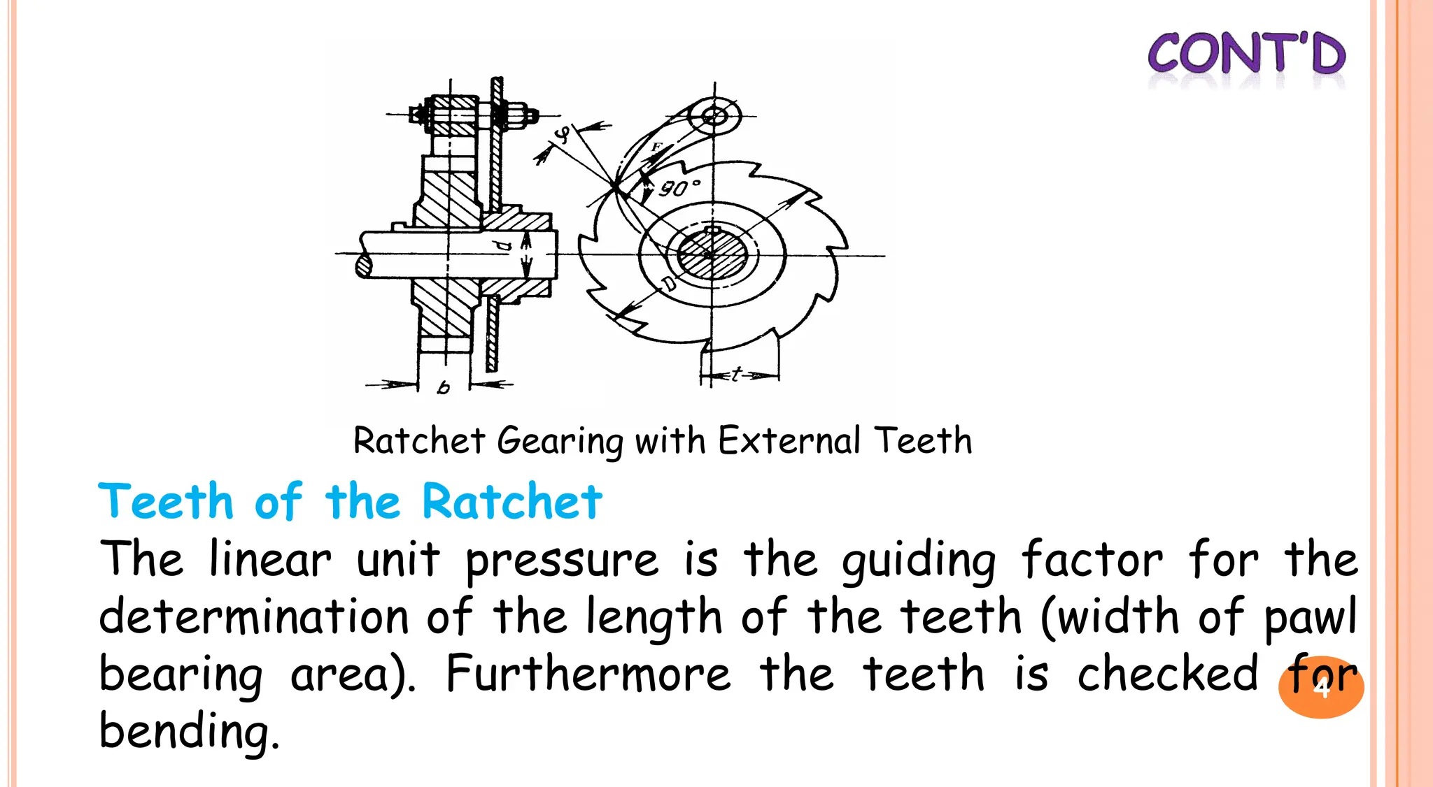
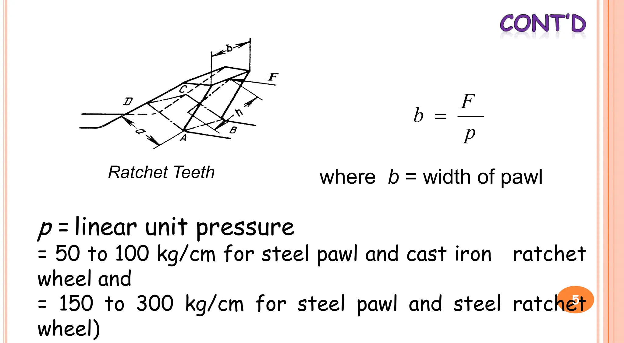
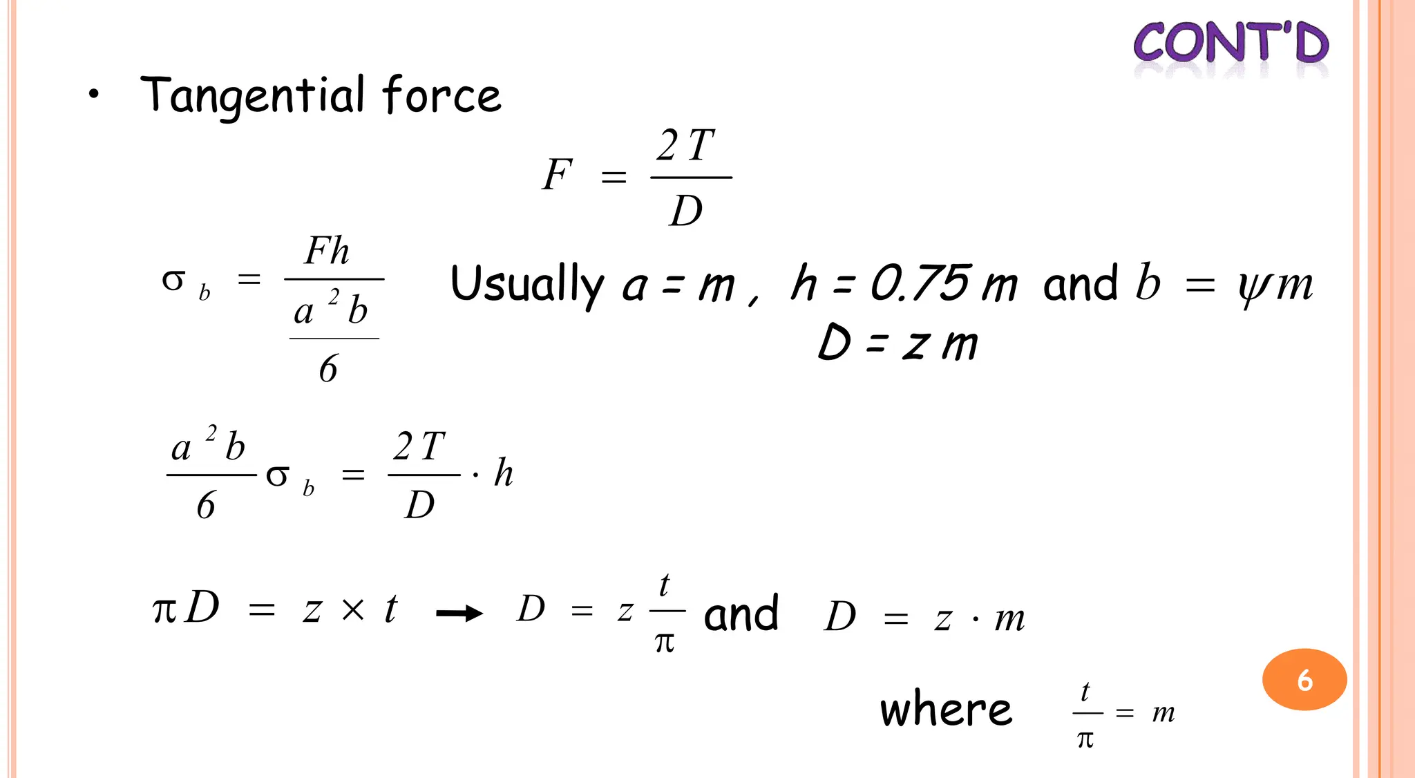
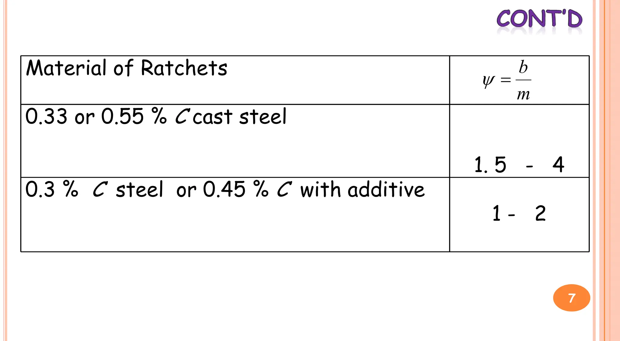
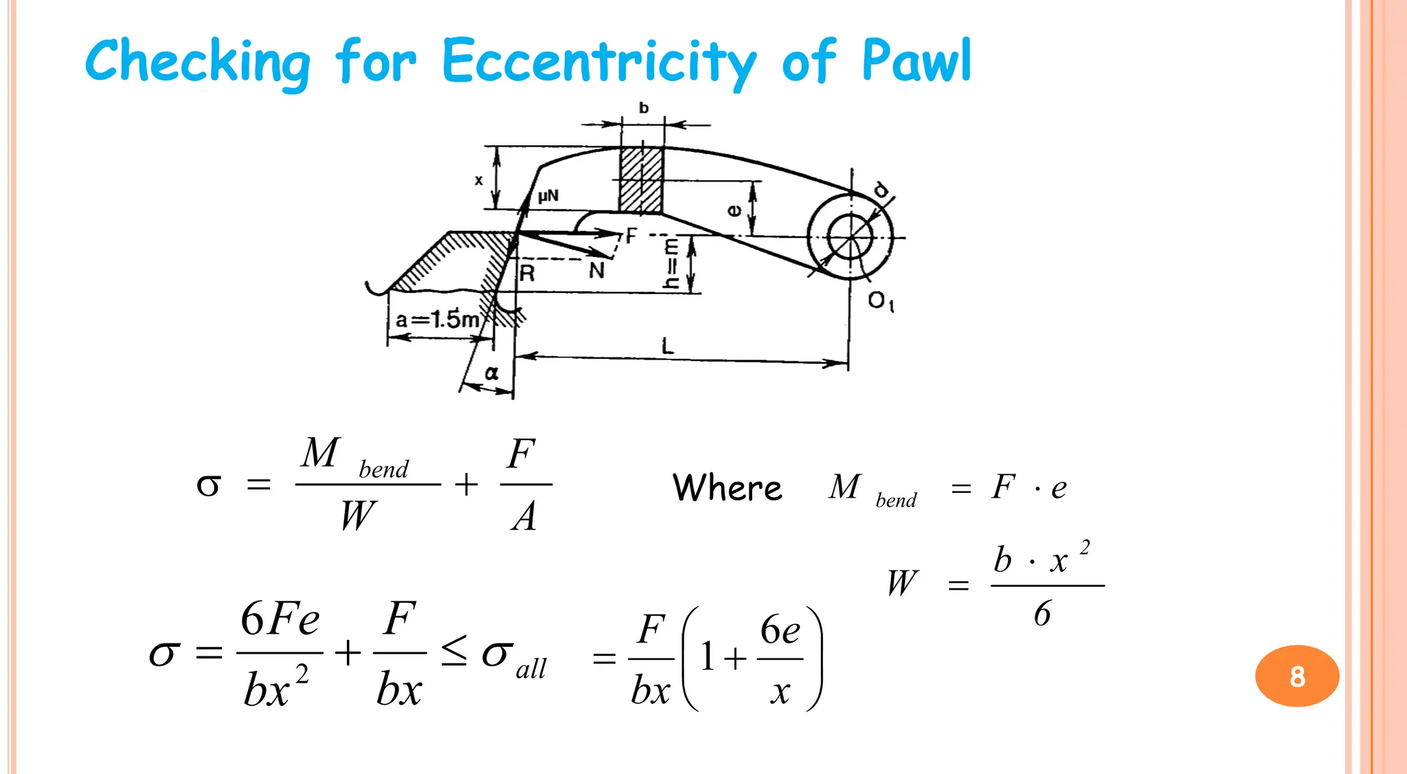
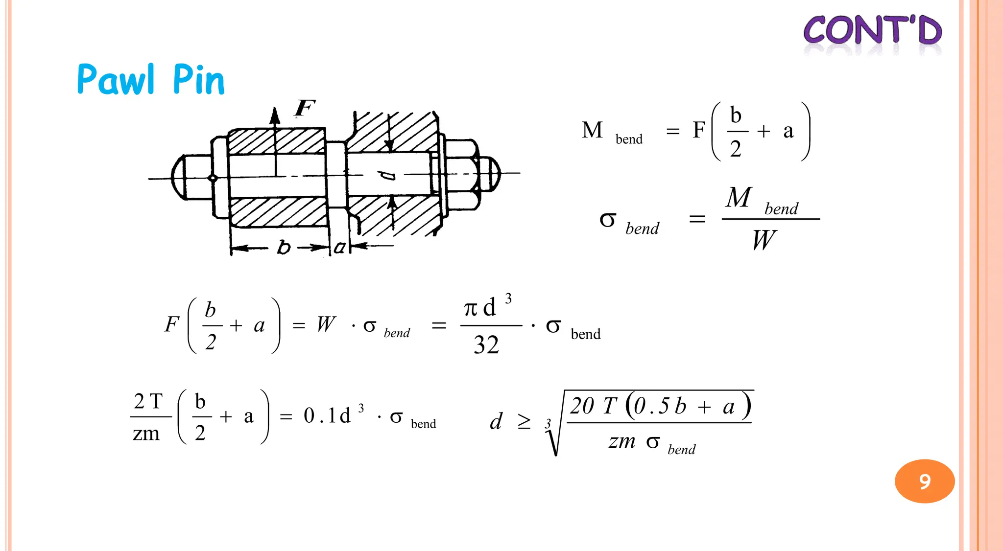
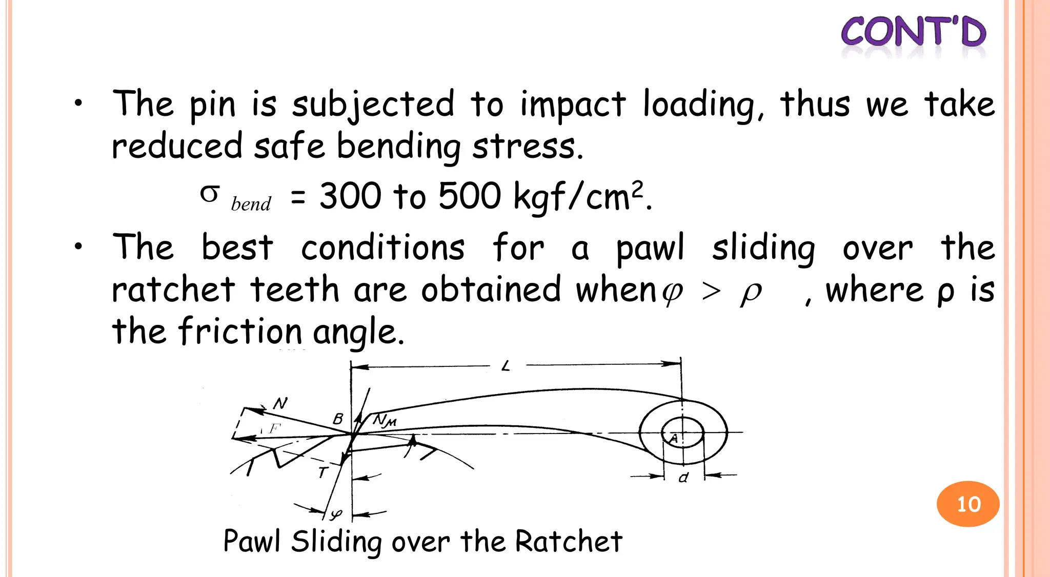
2. Ratchet gearing uses a ratchet gear and pawl such that the ratchet turns freely during lifting but the pawl prevents downward motion. The width of the pawl bearing area is designed to withstand bending stresses.
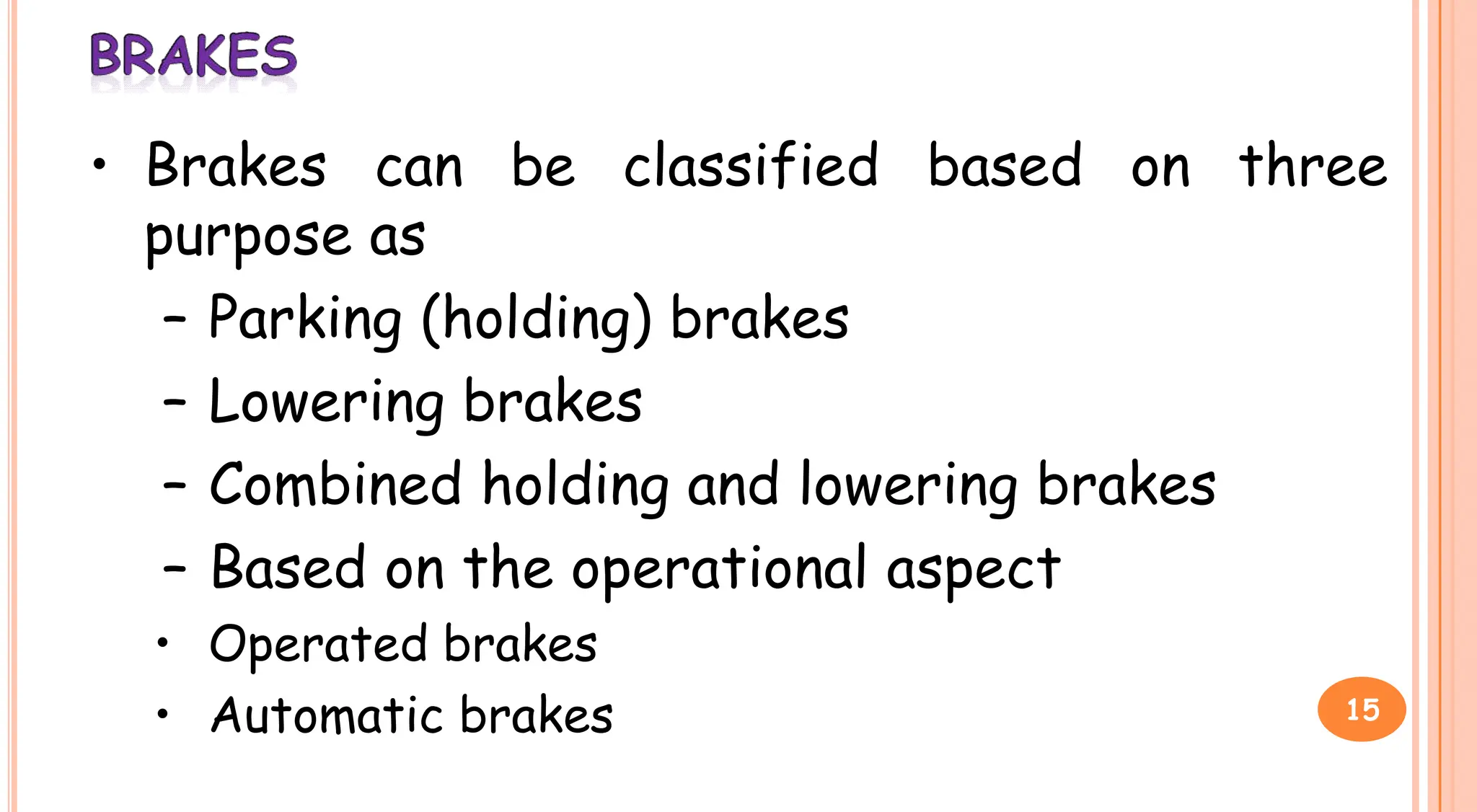
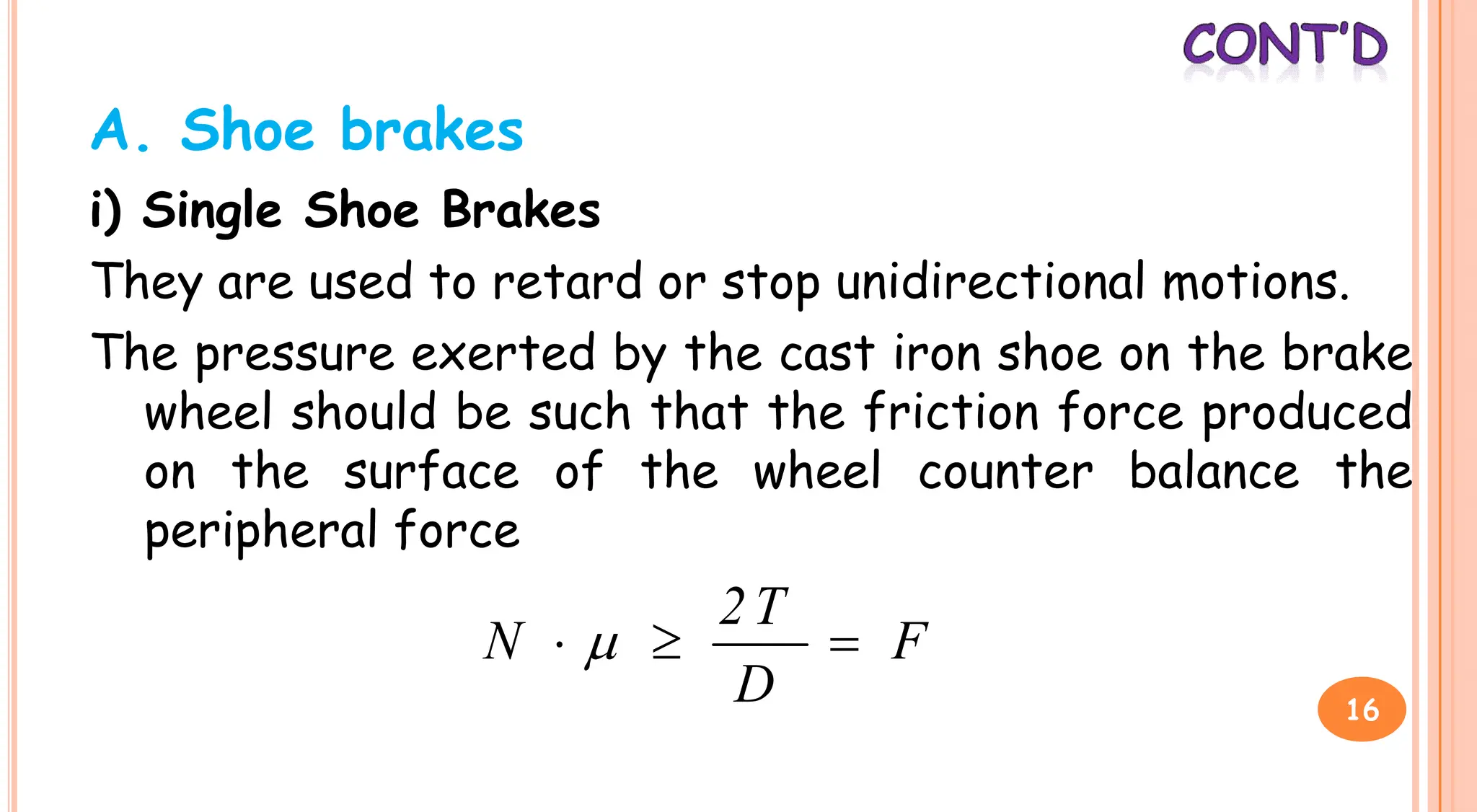
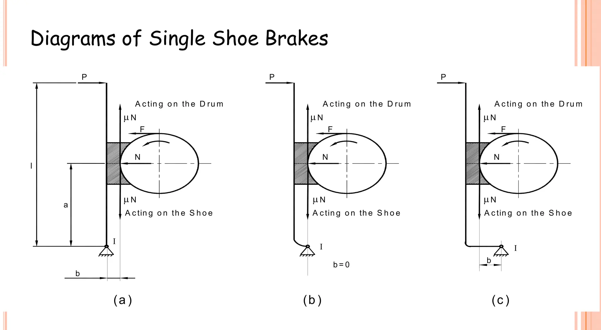
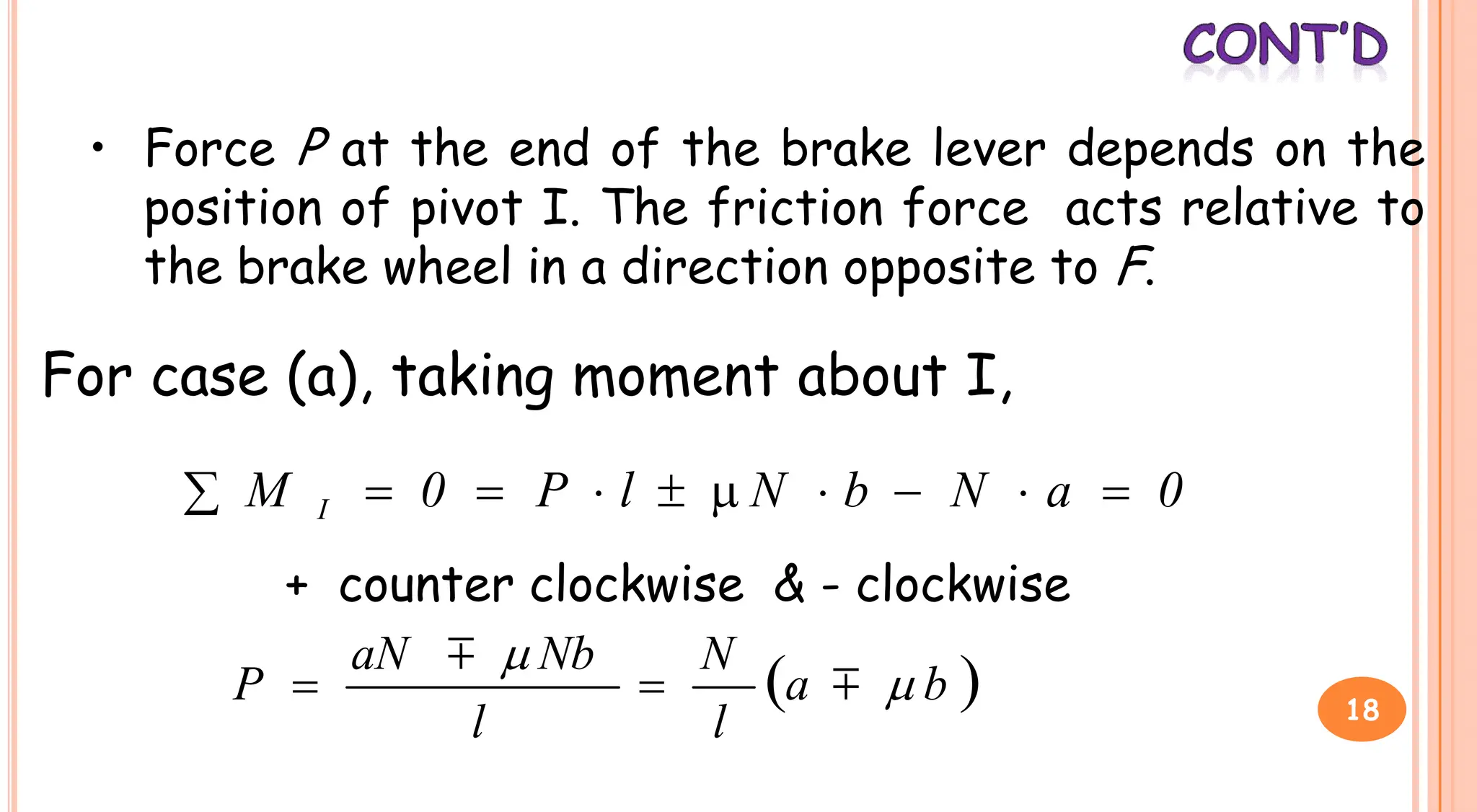
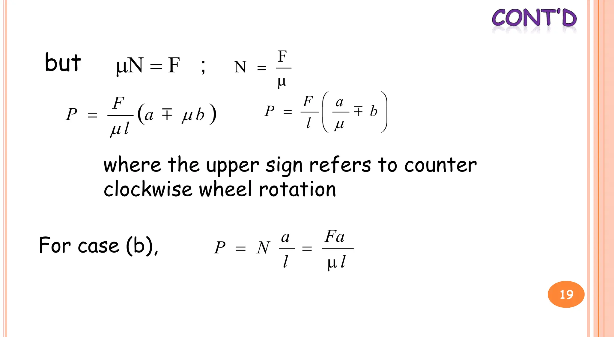
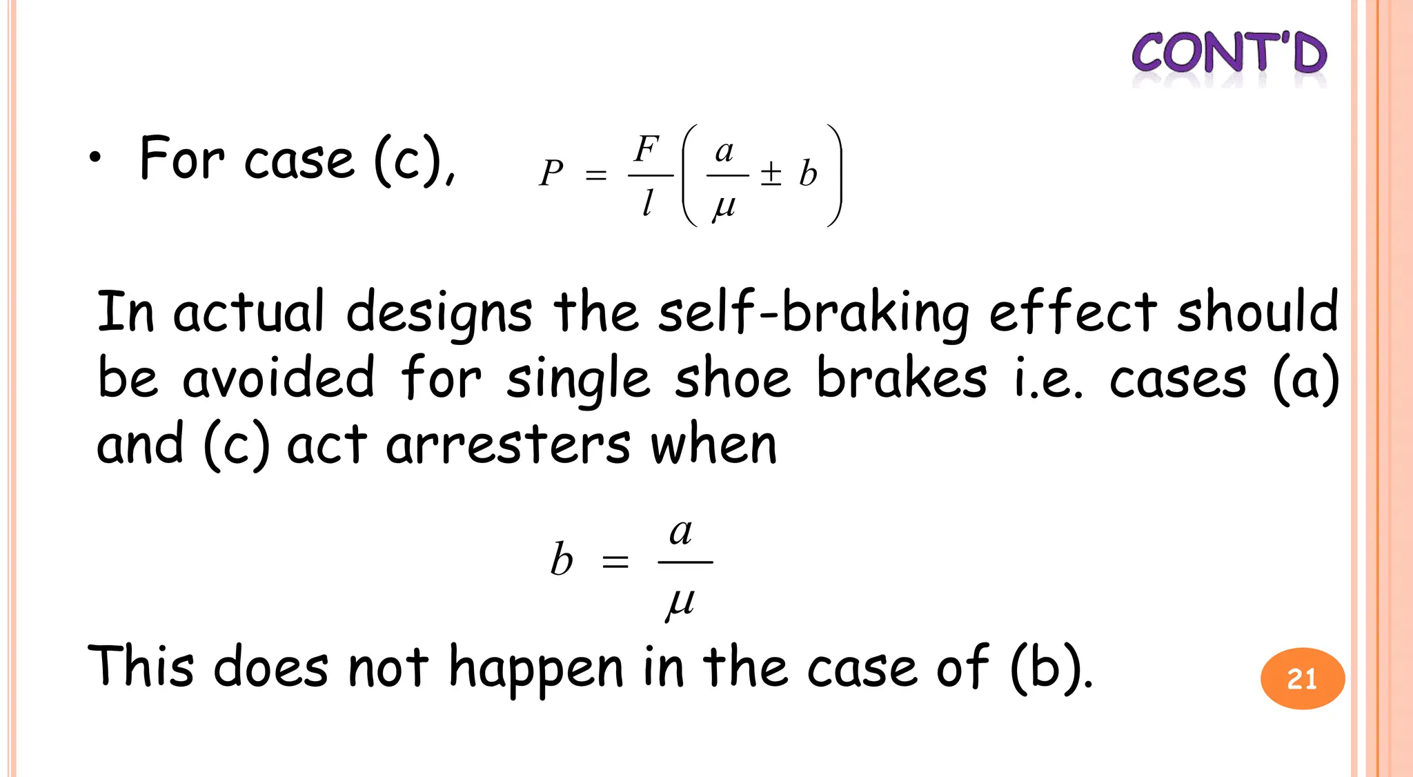
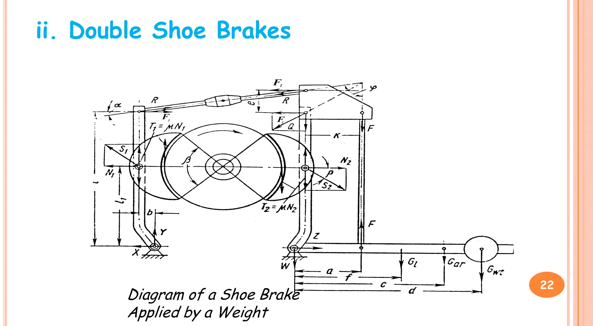
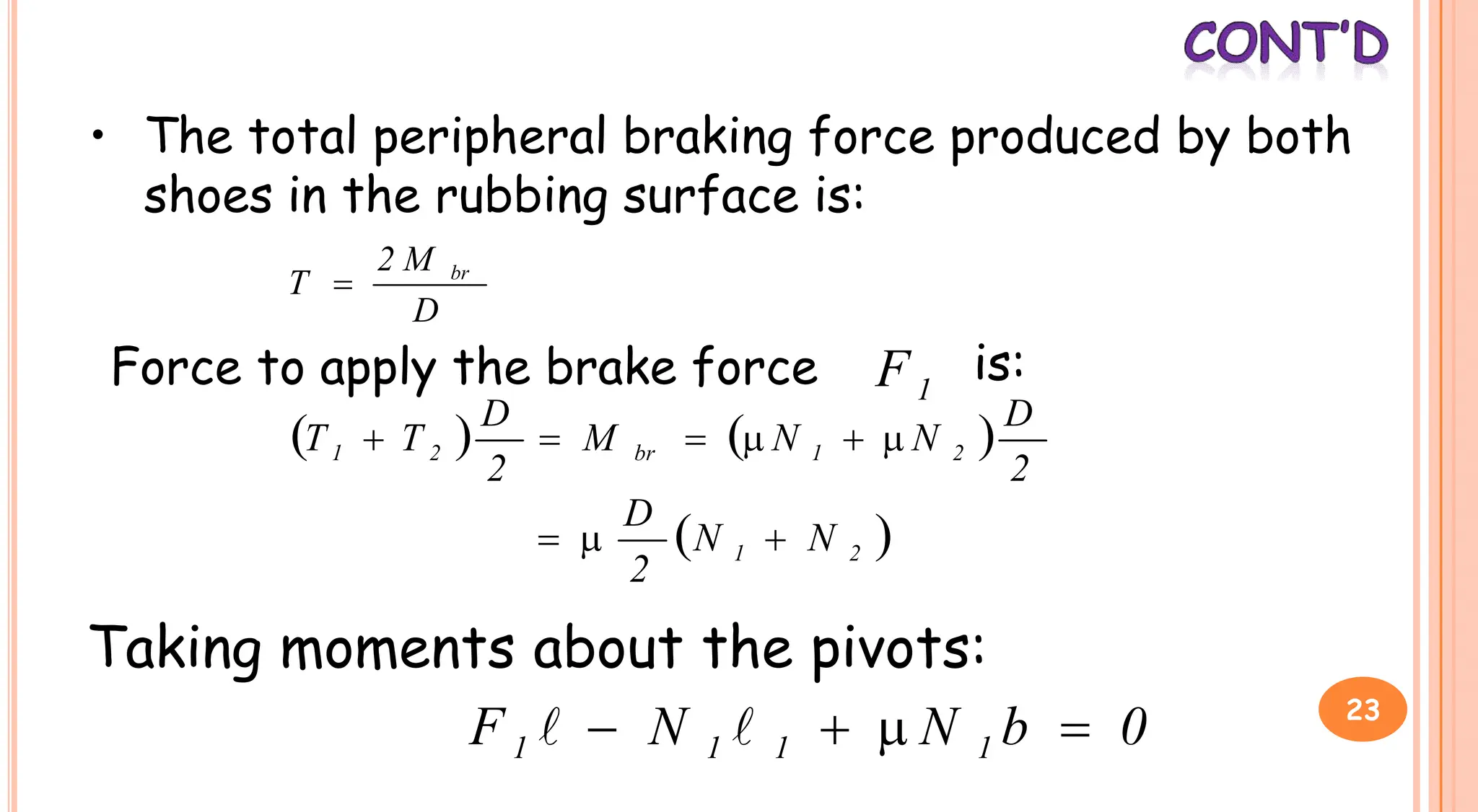
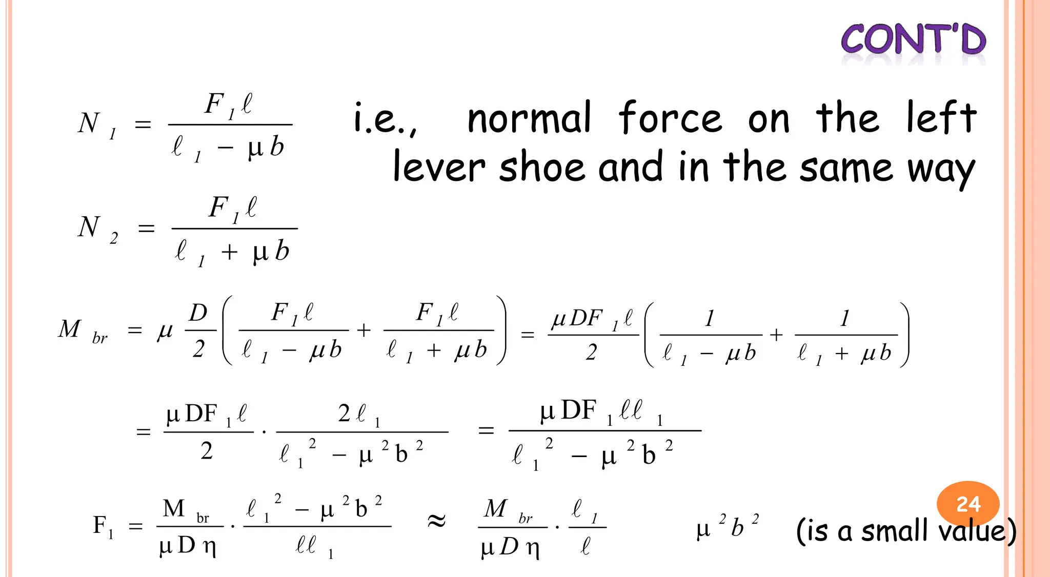
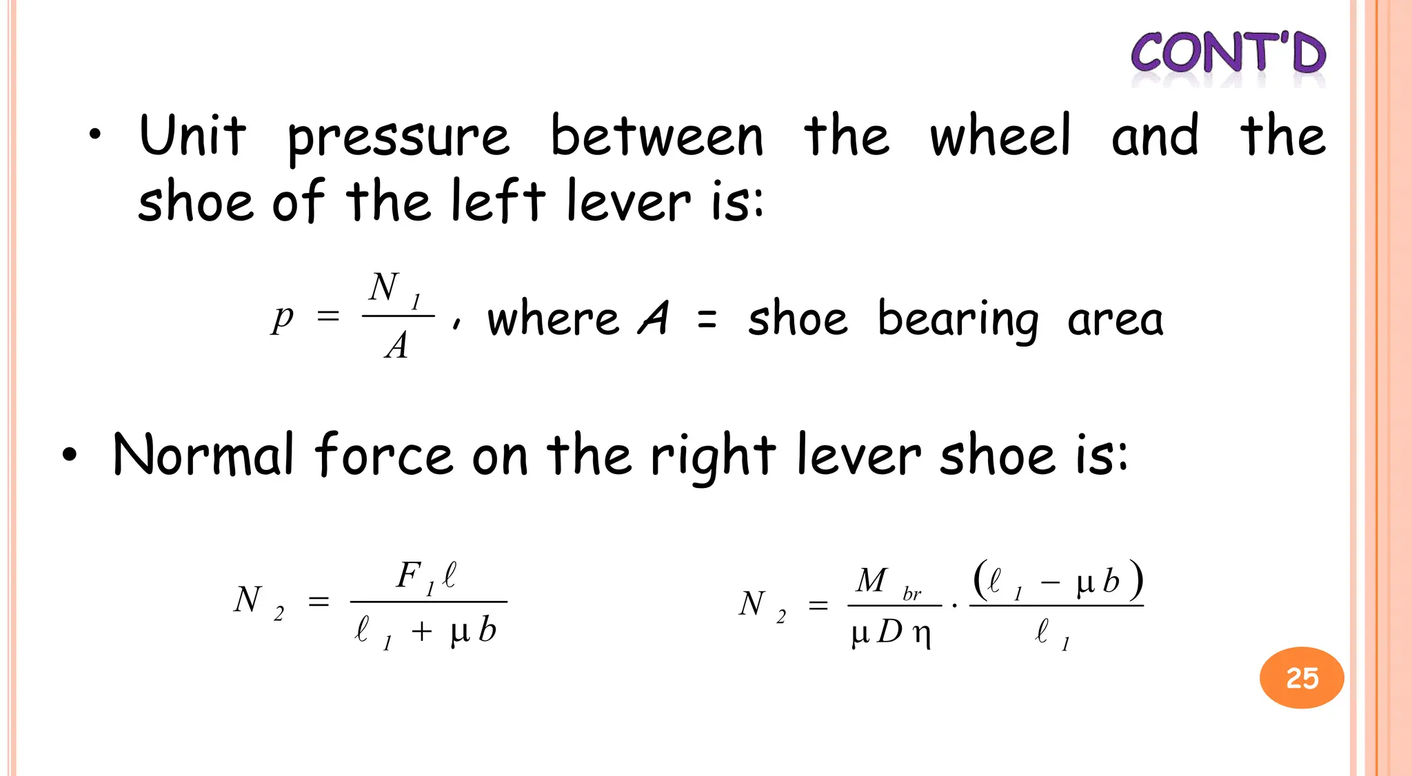
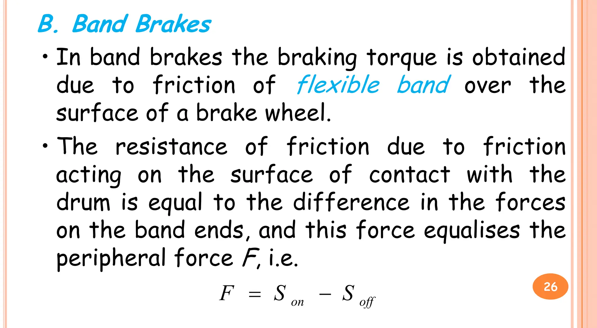
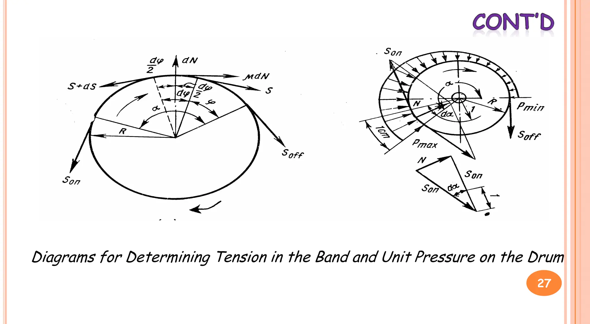
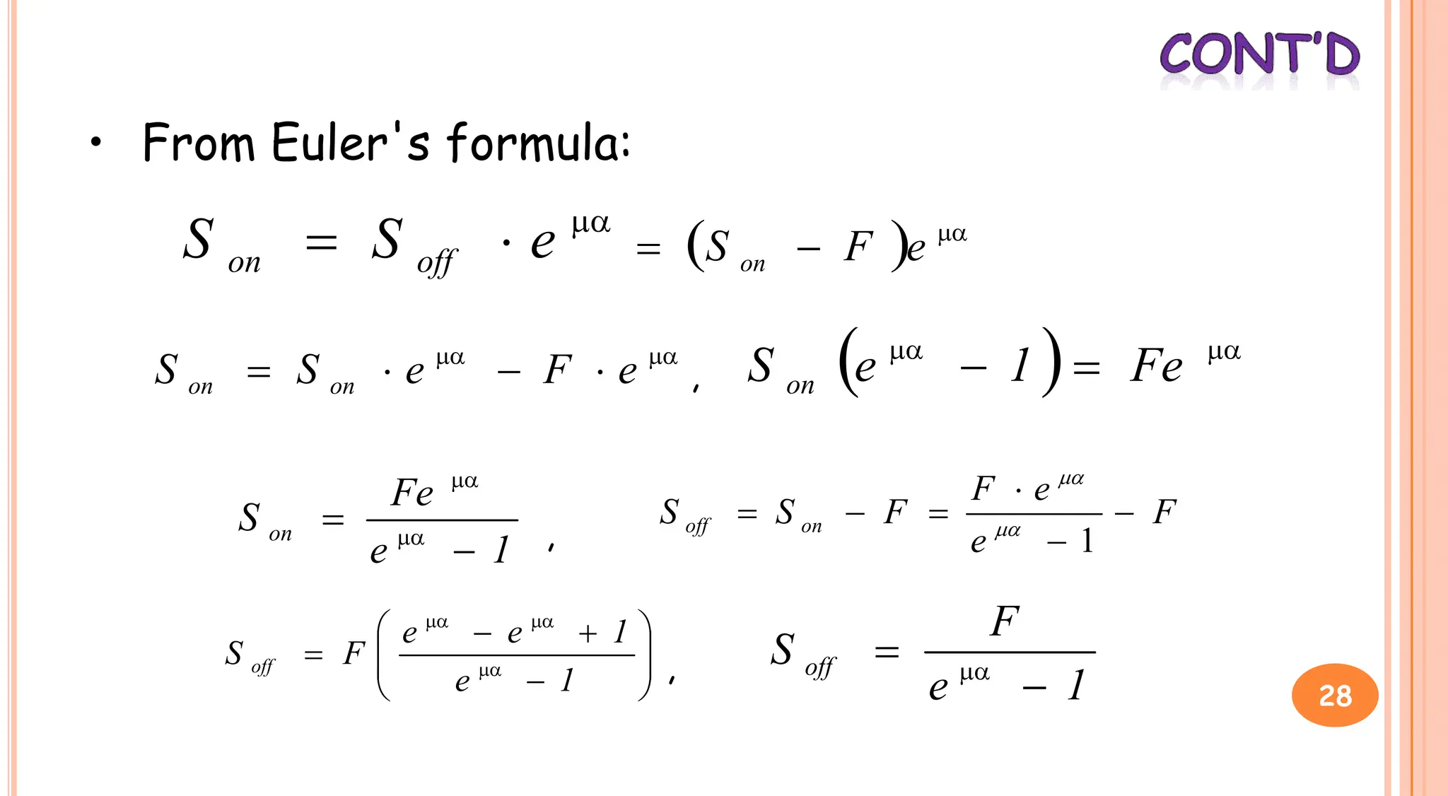
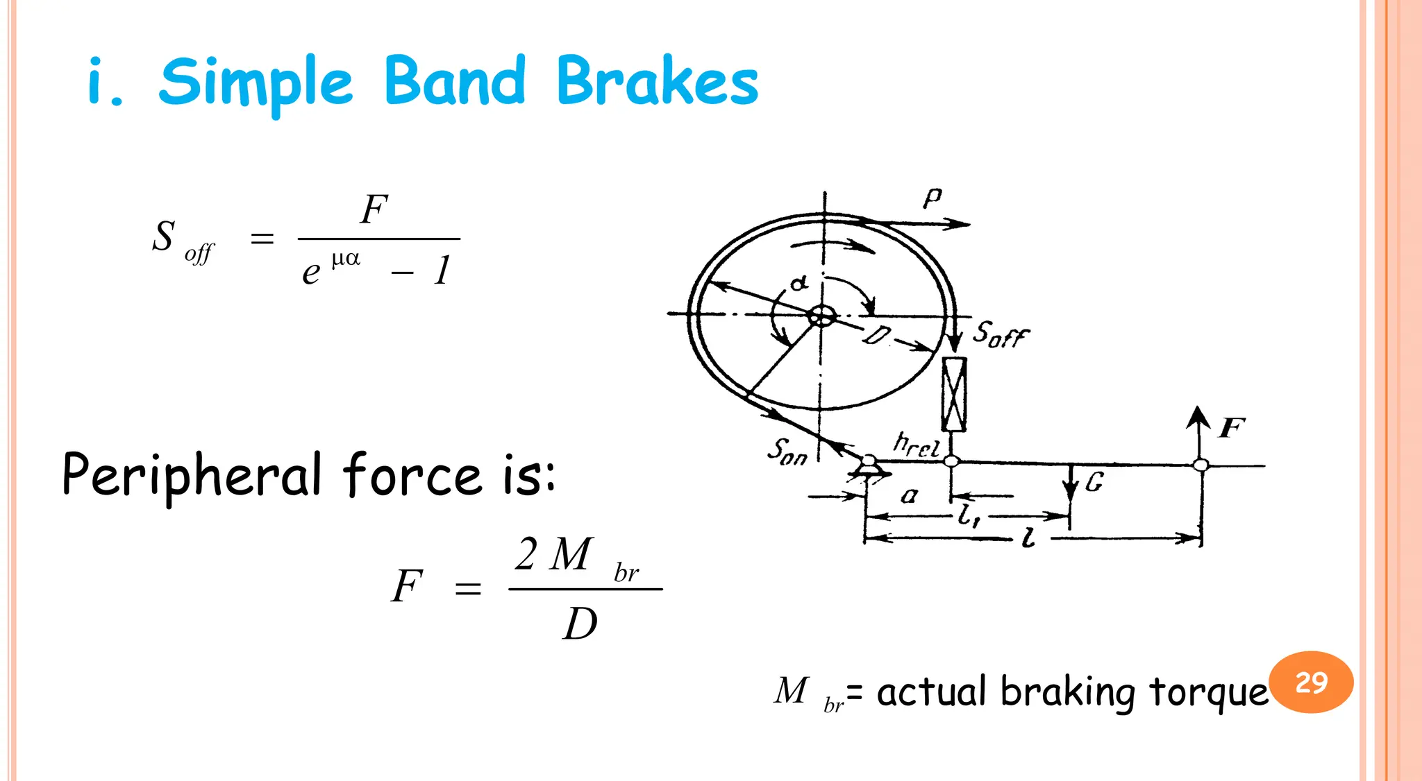
3. Brakes are used to control lowering speed and hold suspended loads stationary. Common brake types include shoe brakes and band brakes, which use friction between a shoe/band and wheel to produce a braking torque opposing motion.