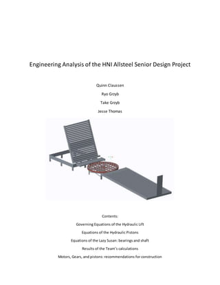
1. Engineering Analysis of the HNI Allsteel Senior Design Project
Quinn Claussen
Ryo Grzyb
Take Grzyb
Jesse Thomas
Contents:
Governing Equations of the Hydraulic Lift
Equations of the Hydraulic Pistons
Equations of the Lazy Susan: bearings and shaft
Results of the Team’s calculations
Motors, Gears, and pistons: recommendations for construction
2. Governing Equations of the Hydraulic Lift:
At the axisof rotation,pointO:
X isthe distance fromthe pointof appliedhydraulicforce topointO
𝛾 is the distance fromthe centerof mass of the table topointO. 𝛾 isalso approximatelyequalto
the distance betweenthe C.O.M.of the largestbulkpacktothe pointO.
(1) ∑ 𝑀𝑜𝑚𝑒𝑛𝑡 𝑂 : 0 = (𝐹𝐻𝑦𝑑𝑟𝑎𝑢𝑙𝑖𝑐)( 𝑆𝑖𝑛𝜃)( 𝑥) − (𝑚𝑔𝑡𝑎𝑏𝑙𝑒)(𝛾) − (𝑚𝑔𝑏𝑢𝑙 𝑘 𝑝𝑎𝑐𝑘)(𝛾)
(2) 𝑊ℎ𝑒𝑟𝑒: 𝛾 = ( 𝑐𝑜𝑠𝜑)
𝑙 𝑡𝑎𝑏𝑙𝑒
2
𝜑 𝑖𝑠 𝑡ℎ𝑒 𝑎𝑛𝑔𝑙𝑒 𝑜𝑓 𝑡𝑎𝑏𝑙𝑒 𝑟𝑖𝑠𝑒
(3) 𝑊ℎ𝑒𝑟𝑒: 𝑥 = ( 𝑐𝑜𝑠𝜃)(𝑙 𝐻𝑦𝑑𝑟𝑎𝑢𝑙𝑖 𝑐 𝐴𝑟𝑚) + 𝑥 𝑜𝑓𝑓𝑠𝑒𝑡 𝜃 𝑖𝑠 𝑡ℎ𝑒 𝑎𝑛𝑔𝑙𝑒 𝑜𝑓 ℎ𝑦𝑑𝑟𝑎𝑢𝑙𝑖𝑐 𝑎𝑟𝑚 𝑟𝑖𝑠𝑒
Note: the offset, 𝑥 𝑜𝑓𝑓𝑠𝑒𝑡 is equal to the distance from the point of hydraulic arm rotation to the frame.
Combining equations one through three:
(4) 𝐹𝐻𝑦𝑑𝑟𝑎𝑢𝑙𝑖𝑐 = ( 𝑐𝑜𝑠𝜑)𝑙 𝑡𝑎𝑏𝑙𝑒
(𝑚𝑔𝑡𝑎𝑏𝑙𝑒) + (𝑚𝑔 𝑏𝑢𝑙𝑘 𝑝𝑎𝑐𝑘)
2(sin( 𝜃) (( 𝑐𝑜𝑠𝜃)(𝑙 𝐻𝑦𝑑𝑟𝑎𝑢𝑙𝑖𝑐 𝐴𝑟𝑚) + 𝑥 𝑜𝑓𝑓𝑠𝑒𝑡))
Note: for clarity, if x = 𝛾, equation four simplifies to a function of the weight of the objects that the pistons move
(5) 𝐹𝐻𝑦𝑑𝑟𝑎𝑢𝑙𝑖𝑐 = (𝑚𝑔𝑡𝑎𝑏𝑙𝑒) + (𝑚𝑔 𝑏𝑢𝑙𝑘 𝑝𝑎𝑐𝑘)
3. Governing Equations of the Hydraulic Pistons:
These equationsrelatethe loadliftedbythe systemtothe pressure insideof eachhydraulic
piston.Hydraulicforce, 𝐹𝐻𝑦𝑑𝑟𝑎𝑢𝑙𝑖 𝑐 isequal totwotimesthe pistonforce, 𝐹𝑃𝑖𝑠𝑡𝑜𝑛 bythe fact that there
are twopistons.
(1) 𝐹𝐻𝑦𝑑𝑟𝑎𝑢𝑙𝑖𝑐 = 2( 𝐹𝑃𝑖𝑠𝑡𝑜𝑛)
(2) 𝐹𝑃𝑖𝑠𝑡𝑜𝑛 = ∆𝐹𝑃𝑟𝑒𝑠𝑠𝑢𝑟𝑒 = 𝐹1 − 𝐹2
(3) 𝐹1 = 𝜋 (
𝑑2
2
− 𝑑1
2
4
) 𝑃1 𝐹2 = 𝜋(
𝑑2
2
4
) 𝑃2 𝐹𝑟𝑜𝑚 𝑡ℎ𝑒 𝑎𝑏𝑜𝑣𝑒 𝑖𝑚𝑎𝑔𝑒
Note: the pressure 𝑃1 is what must be provided by a compressor in order to overcome the forces and lift the table.
The force on the other side, 𝐹2 is equal to the forces dispersed across the piston head dueto the lift table’s
weight.
4. Governing Equations of the Lazy Susan Bearing Assembly:
The torque is equal to the product of the moment of inertia and the angular acceleration which can be
assumed to be very small.
(1) 𝑇 = 𝐼𝛼
The torque is alsoequal tothe productof the frictionforce causedbythe ball bearingsmultipliedby the
radius of the bearings from the axis of movement functioning as a moment arm.
(2) 𝑇 = (𝐹𝑑𝑦𝑛𝑎𝑚𝑖𝑐 𝑓𝑟𝑖𝑐𝑡𝑖𝑜𝑛)𝑟
The dynamic friction of the assembly can be calculated using the friction coefficient of a ball bearing
multiplied by the normal force on the ball bearings, N.
(3) 𝐹𝑑𝑦𝑛𝑎𝑚𝑖𝑐 𝑓𝑟𝑖𝑐𝑡𝑖𝑜𝑛 = 𝜇 𝑏𝑎𝑙𝑙 𝑏𝑒𝑎𝑟𝑖 𝑛 𝑔 𝑁
Clockwisefromthe top:
Dynamicview
Bearing assembly close-up
Motorand gearview
5. Governing Equations of the Lazy Susan ShaftStress:
The maximumstressexperiencedbythe shaftisa designrequirementforthissystem. The max
stresson the shaftwheninrotational motionisequal to 𝜏. 𝜏 inturn isrelatedto the maximum
torque experienced,T,the radiusfromthe centerof the shaftto the outerskinof the shaft,r, and
the polar momentof inertia,Jasdescribedinequation(1).
(1) 𝜏 =
(𝑇 𝑚𝑎𝑥)𝑟
𝐽
𝑁𝑜𝑡𝑒: 𝑇ℎ𝑒 𝜏 𝑒𝑥𝑒𝑟𝑡𝑒𝑑 𝑑𝑢𝑟𝑖𝑛𝑔 𝑟𝑜𝑡𝑎𝑡𝑖𝑜𝑛 𝑖𝑠 𝑓𝑜𝑢𝑛𝑑 𝑏𝑦 𝑢𝑠𝑖𝑛𝑔 𝑡ℎ𝑒 𝑇 𝑚𝑎𝑥 𝑓𝑟𝑜𝑚 𝑒𝑞𝑢𝑎𝑡𝑖𝑜𝑛 2 𝑜𝑓 𝑡ℎ𝑒 𝑏𝑒𝑎𝑟𝑖𝑛𝑔 𝑎𝑠𝑠𝑒𝑚𝑏𝑙𝑦.
In orderto findthe 𝜏 experiencedatinitialization,anew 𝑇 𝑚𝑎𝑥 mustbe calculatedbasedonthe
angularaccelerationattime = 0, 𝛼0.
(2) 𝑇 𝑚𝑎𝑥 = 𝐼𝛼0 =
𝑚𝑟2
2
𝛼0
Assume max shearstressbasedonmaterial propertiesinordertofind 𝑇 𝑚𝑎𝑥 andthen 𝛼0 by plugging
equation(3) intoequation(2).
(3) 𝑇 𝑚𝑎𝑥 =
𝜏𝐽
𝑟
6. Results of the Team’s Calculations:
A. The Hydraulic Lift
(1) ∑𝑀𝑜𝑚𝑒𝑛𝑡 𝑂 :0 = (𝐹𝐻𝑦𝑑𝑟𝑎𝑢𝑙𝑖 𝑐)( 𝑆𝑖𝑛𝜃)( 𝑥) − (𝑚𝑔𝑡𝑎𝑏𝑙𝑒)(𝛾) − (𝑚𝑔 𝑏𝑢𝑙𝑘 𝑝𝑎𝑐𝑘)(𝛿)
(2) 𝑊ℎ𝑒𝑟𝑒: 𝛾 = ( 𝑐𝑜𝑠𝜑)
𝑙 𝑡𝑎𝑏𝑙𝑒
2
𝜑 𝑖𝑠 𝑡ℎ𝑒 𝑎𝑛𝑔𝑙𝑒 𝑜𝑓 𝑡𝑎𝑏𝑙𝑒 𝑟𝑖𝑠𝑒
When 𝜑 = 0° 𝑎𝑛𝑑 𝜃 = 10° the lift table is flat and at its highest resistance to movement
Distances from the center of rotation to the point of application of force
𝑥 = [(21.9𝑖𝑛)(cos( 𝜃)) + 5.24𝑖𝑛](.0254
𝑚
𝑖𝑛
) 𝛾 = (
70𝑖𝑛
2
)(. 0254
𝑚
𝑖𝑛
) 𝛿 = (
65𝑖𝑛
2
)(.0254
𝑚
𝑖𝑛
)
Plugging in the values of distances from the C.O.M. to equation (4):
(4) 𝐹𝐻𝑦𝑑𝑟𝑎𝑢𝑙𝑖𝑐 = ( 𝑐𝑜𝑠𝜑)𝑙 𝑡𝑎𝑏𝑙𝑒
(𝑚𝑔𝑡𝑎𝑏𝑙𝑒) + (𝑚𝑔 𝑏𝑢𝑙𝑘 𝑝𝑎𝑐𝑘)
2(sin( 𝜃) (( 𝑐𝑜𝑠𝜃)(𝑙 𝐻𝑦𝑑𝑟𝑎𝑢𝑙𝑖𝑐 𝐴𝑟𝑚) + 𝑥 𝑜𝑓𝑓𝑠𝑒𝑡))
𝐹𝐻𝑦𝑑𝑟𝑎𝑢𝑙𝑖 𝑐 = ( 𝑐𝑜𝑠0°)(70𝑖𝑛)
(222.722𝑘𝑔 ∗ 9.81
𝑚
𝑠2)+ (45.3592𝑘𝑔 ∗ 9.81
𝑚
𝑠2)
2(sin(10°)(( 𝑐𝑜𝑠10°)(21.9𝑖𝑛)+ 5.24𝑖𝑛))
𝑭 𝑯𝒚𝒅𝒓𝒂𝒖𝒍𝒊𝒄 = 𝟏𝟗𝟕𝟕𝟑. 𝟑𝟓 𝑵 𝒐𝒓 𝟒𝟒𝟒𝟓.𝟐𝟑 𝑷𝒐𝒖𝒏𝒅𝒔 𝑭𝒐𝒓𝒄𝒆
B. The Hydraulic Pistons
(1) 𝐹𝐻𝑦𝑑𝑟𝑎𝑢𝑙𝑖𝑐 = 2( 𝐹𝑃𝑖𝑠𝑡𝑜𝑛)
𝐹𝑃𝑖𝑠𝑡𝑜𝑛 = 2222.62 𝑃𝑜𝑢𝑛𝑑𝑠 𝐹𝑜𝑟𝑐𝑒
(2) 𝐹𝑃𝑖𝑠𝑡𝑜𝑛 = ∆𝐹𝑃𝑟𝑒𝑠𝑠𝑢𝑟𝑒 = 𝐹1 − 𝐹2
The pump must provide 2222.62 pounds force if 𝐹2 = 0.
(3) 𝐹1 = 𝜋(
𝑑2
2
− 𝑑1
2
4
) 𝑃1 𝐹2 = 𝜋 (
𝑑2
2
4
) 𝑃2
8. D. The Lazy Susan ShaftStress
Known:
𝑇 𝑚𝑎𝑥 =
𝜏𝐽
𝑟
Assume that maximum shear stress, 𝜏, equals 10.9E6 lb/in^2 by material properties
𝑟𝑠ℎ𝑎𝑓𝑡 = 0.25𝑖𝑛 = 0.00635𝑚 𝐽 = (
𝜋
2
) 𝑟4 𝑚 𝑡𝑜𝑡𝑎𝑙 = 158.887𝑙𝑏 = 72.0799𝑘𝑔
Find 𝑇 𝑚𝑎𝑥 using a modified equation (1).
(1) 𝜏 =
(𝑇 𝑚𝑎𝑥)𝑟
𝐽
𝑇 𝑚𝑎𝑥 =
(10.9𝐸6
𝑙𝑏
𝑖𝑛2)(
𝜋
2
) . 254
.25
= 280000 𝐈𝐧𝐜𝐡 𝐏𝐨𝐮𝐧𝐝𝐬 𝐨𝐟 𝐅𝐨𝐫𝐜𝐞
And plug that value into equation (1) from the bearings equations
(1) 𝑇 = 𝐼𝛼
Using the moment of inertia for a solid disk and the angular acceleration 𝛼0 at t=0:
𝑇 =
𝑚𝑟 𝑑𝑖𝑠𝑘
2
2
𝛼0 where 𝑟𝑑𝑖𝑠𝑘
2 = 756.25𝑖𝑛2 = 0.4879𝑚2
Substitute, 𝑇 𝑚𝑎𝑥 for 𝑇 and find 𝛼.
3082.23578 𝑚 ∗ 𝑘𝑔 =
72.0799 ∗ 0.4879𝑚2
2
𝛼0
𝜶 𝟎 = 𝟏𝟕𝟓. 𝟐𝟗
𝒓𝒂𝒅
𝒔 𝟐
Can be experienced before the maximum shear stress is exceeded
9. Motors, Gears, and pistons: recommendations for construction
Tipper – Hydraulic/Pneumatics
o Our calculations show that the cylinder will have to overcome a force of
approximately 1400 lbs per cylinder. Which results in the need of a hydraulic
cylinder.
o Pneumatic cylinders were considered because they are a simpler and cheaper option
compared to the hydraulic system. However, it might not be able to handle the load.
http://www.mcmaster.com/#62205k723/=11jw1rv
Lazy susan – electric motor
o The calculation shows that a torque of approximately 6.5 inch-pounds is needed to
rotate the lazy susan. The lazy susan will be powered by a DC gearmotor.
http://www.mcmaster.com/#6470k71/=11jw78h
Misc.
http://www.mcmaster.com/#hydraulic-reservoirs/=11jvrqn - hydraulic resevoir
http://www.mcmaster.com/#Hydraulic-Pumps - hydraulic pumps
http://www.mcmaster.com/#hydraulic-valves/=11jw8y5 - hydraulic valve
http://www.mcmaster.com/#6867k52/=11jw6vs – gear, 3 inch Pitch dia.
http://www.mcmaster.com/#6867k41/=11jw6hp – gear, 1 inch Pitch dia.