Download to read offline

![P. L. N. V. Aashrith Int. Journal of Engineering Research and Applications www.ijera.com
ISSN : 2248-9622, Vol. 4, Issue 6( Version 1), June 2014, pp.70-79
www.ijera.com 78 | P a g e
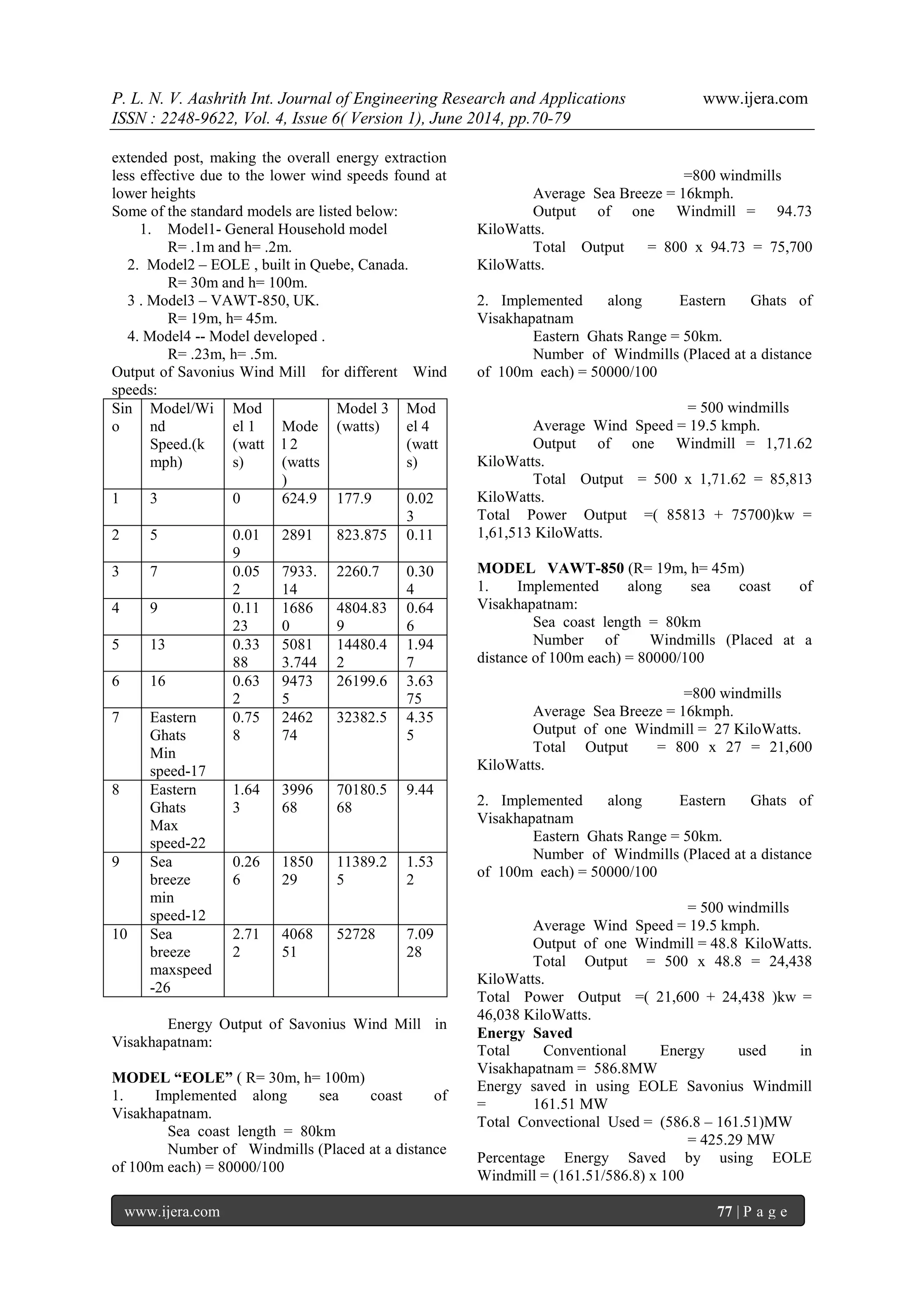
= 27.52% Energy saved in using VAWT-850 Savonius Windmill = 46.03 MW Total Convectional Used = (586.8-46.03) MW = 540.77 MW Percentage Energy Saved by using VAWT-850 Windmill = (46.03/586.8) x 100. = 7.8%
VII. ADVANTAGES OF SAVONIUS WIND MILL
a) It is a renewable source of energy. b) Wind power systems are non-polluting so it has no adverse influence on the environment. c) Wind energy systems avoid fuel provision and transport. d) On a small scale up to a few kilowatt system is less costly. e) On a large scale costs can be competitive conventional electricity and lower costs could be achieved by mass production. f) They are always facing the wind - no need for steering into the wind. g) Have greater surface area for energy capture -can be many times greater. h) Are more efficient in gusty winds – already facing the gust. i) Can be installed in more locations - on roofs, along highways, in parking lots. j) Can be scaled more easily - from mill watts to megawatts.
VIII. ADVANTAGE OF SAVONIUS WIND TURBINE OVER HORIZONTAL AXIS WIND TURBINE
There are several reasons why we would choose a vertical axis wind turbine over a horizontal axis windmill. 1. They are mounted lower to the ground making it easy for maintenance if needed. 2. They start creating electricity at speeds of only 6 mph. And 3. Third, they may be able to be built at locations where taller structures, such as the horizontal type, can't be. 4. Higher power utilization-- 20% higher than HAWT. 5. Lower noise level--only 27-37 DB, suitable for your living condition. 6. Safer operation--Spin at slower speeds than horizontal turbines, decreasing the risk of injuring birds and also decreasing noise level.
IX. CONCLUSION
Vertical axis wind energy conversion systems are practical and potentially very contributive to the production of clean renewable electricity from the wind even under less than ideal sitting conditions. It is hoped that they may be constructed used high- strength, low- weight materials for deployment in more developed nations and settings or with very low tech local materials and local skills in less developed countries. The Savonius wind turbine designed is ideal to be located on top of a bridge or bridges to generate electricity, powered by wind. The elevated altitude gives it an advantage for more wind opportunity. With the idea on top of a bridge, it will power up street lights and or commercial use. In most cities, bridges are a faster route for everyday commute and in need of constant lighting makes this an efficient way to produce natural energy. REFERENCES [1] Peter, C., Sheets, B. and Tablar, S. (2008): Emerging Technologies in the Wind Turbine Market, The Palace Hotel, San Francisco, CA. 19-20 November 2008. [2] Manwell, J.F., McGowan, J.G. and Rogers, A.L. (2009): Wind Energy Explained UK, John Wiley & Son Ltd. [3] Akwa, J.V., Junior, G.A.S. and Petry, A.P. (2012): Discussion on the Verification of the Overlap Ratio Influence on Performance Coefficients of a Savonius Wind Rotor Using Computational Fluid Dynamics. Renewable Energy, Vol.38, pp.141-149. [4] Halsey, N. (2011): Modeling the Twisted Savonius Wind Turbine Geometrically and Simplifying its Construction. Oregon Episcopal School. [5] D’Alessandro, V., Montelpare, S., Ricci, R. and Secchiaroli, A. (2010): Unsteady Aerodynamics of a Savonius Wind Rotor: A New Computational Approach for the Simulation of Energy Performance. Energy, Vol.35, pp. 3349-3363. [6] Islam, M.Q., Hasan, M.N. and Saha, S. (2005): Experimental Investigation of Aerodynamic Characteristics of Two, Three and Four Bladed S-Shaped Stationary Savonius Rotors. The Proceeding of International Conference on Mechanical Engineering 2005, 28-30 December 2005, Dhaka, Bangladesh. [7] Musgrove, P. (2010): Wind Power, UK: Cambridge University Press.
[8] Hayashi, T., Yan, L. and Suzuki, K. (2004): Wind Tunnel Tests on a Three-stage Out- phase Savonius Rotor. [Online]. Available at: http://www.2004ewec.info/files/231400_tsuto](https://image.slidesharecdn.com/m046017079-140904034147-phpapp02/75/M046017079-9-2048.jpg)
![P. L. N. V. Aashrith Int. Journal of Engineering Research and Applications www.ijera.com
ISSN : 2248-9622, Vol. 4, Issue 6( Version 1), June 2014, pp.70-79
www.ijera.com 79 | P a g e
muhayashii_01.pdf [Accessed on 13 November 2011]. [9] Jain, P. (2011): Wind Energy Engineering, McGraw-Hill, New York. [10] Johnson, C. (1998): Practical Wind- Generated Electricity. [Online]. Available at: http://mbsoft.com/public/wind.html [Accessed on 24 April 2012]. [11] Solanki, C.S. (2009): Renewable Energy Technologies: A Practical Guide for Beginners, PHI Learning Private Limited, New Delhi, pp.103-106. [12] Saha, U.K., Thotla, S. and Maity, D. (2008): Optimum Design Configuration of Savonius Rotor Through Wind Tunnel Experiments. Journal of Wind Engineering and Industrial Aerodynamics, Vol.96, pp.1359-1375.](https://image.slidesharecdn.com/m046017079-140904034147-phpapp02/75/M046017079-10-2048.jpg)

The document describes the design and fabrication of a Savonius wind mill. It discusses the various components of the wind mill including the rotor, shaft, and shell type transformer. Formulas are provided for calculating the kinetic energy of air, power produced by the turbine, and efficiency factors like torque coefficient and power coefficient. The fabrication process involves cutting, drilling, bending, and assembling PVC pipes, plywood, and other materials to construct the vertical axis wind turbine.


