2
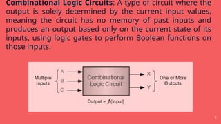
Combinational Logic Circuits:A type of circuit where the
output is solely determined by the current input values,
meaning the circuit has no memory of past inputs and
produces an output based only on the current state of its
inputs, using logic gates to perform Boolean functions on
those inputs.
3.
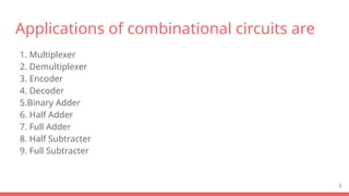
Applications of combinationalcircuits are
1. Multiplexer
2. Demultiplexer
3. Encoder
4. Decoder
5.Binary Adder
6. Half Adder
7. Full Adder
8. Half Subtracter
9. Full Subtracter
3
4.
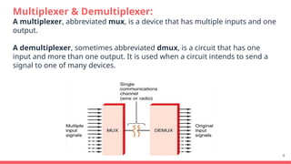
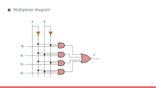
Multiplexer & Demultiplexer:
Amultiplexer, abbreviated mux, is a device that has multiple inputs and one
output.
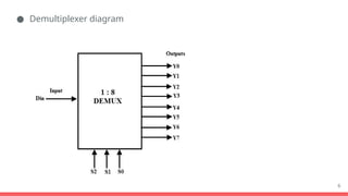
A demultiplexer, sometimes abbreviated dmux, is a circuit that has one
input and more than one output. It is used when a circuit intends to send a
signal to one of many devices.
4
7
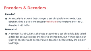
Encoder?
● An encoderis a circuit that changes a set of signals into a code. Let’s
begin making a 2-to-1 line encoder truth table by reversing the 1-to-2
decoder truth table.
Decoders?
● A decoder is a circuit that changes a code into a set of signals. It is called
a decoder because it does the reverse of encoding, but we will begin our
study of encoders and decoders with decoders because they are simpler
to design.
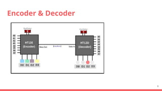
Encoders & Decoders
Binary Adders
9
A BinaryAdder is an electronic circuit that sums two binary
numbers.
The most basic types are half adders and full adders.
A half adder takes in two one-bit numbers, producing a sum and a
carry bit.
Full adder have three input bits-two actual bits and an incoming
carry from the preceding operation.
10.
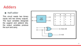
Adders
● Half adder
10
Thiscircuit needs two binary
inputs and two binary outputs.
The input variables designate
the augend and addend bits;
the output variables produce
the sum and carry.
11.
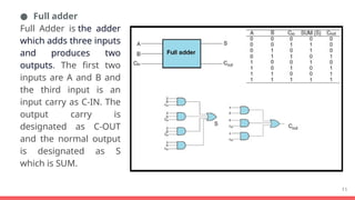
● Full adder
FullAdder is the adder
which adds three inputs
and produces two
outputs. The first two
inputs are A and B and
the third input is an
input carry as C-IN. The
output carry is
designated as C-OUT
and the normal output
is designated as S
which is SUM.
11
12.
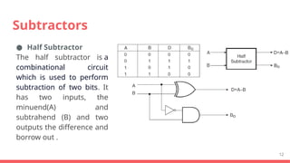
● Half Subtractor
Thehalf subtractor is a
combinational circuit
which is used to perform
subtraction of two bits. It
has two inputs, the
minuend(A) and
subtrahend (B) and two
outputs the difference and
borrow out .
12
Subtractors
13.
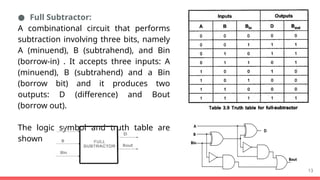
● Full Subtractor:
Acombinational circuit that performs
subtraction involving three bits, namely
A (minuend), B (subtrahend), and Bin
(borrow-in) . It accepts three inputs: A
(minuend), B (subtrahend) and a Bin
(borrow bit) and it produces two
outputs: D (difference) and Bout
(borrow out).
The logic symbol and truth table are
shown
13
14.
Example of CombinationalLogic Circuits
14
Design of logic circuit for control of water pumping
Design of building alarm device
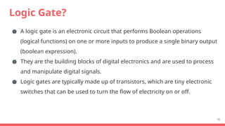
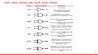
Logic Gate?
● Alogic gate is an electronic circuit that performs Boolean operations
(logical functions) on one or more inputs to produce a single binary output
(boolean expression).
● They are the building blocks of digital electronics and are used to process
and manipulate digital signals.
● Logic gates are typically made up of transistors, which are tiny electronic
switches that can be used to turn the flow of electricity on or off.
16
17.
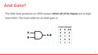
And Gate?
The ANDGate produces an HIGH output when all of its inputs are at logic
level HIGH. The truth table for an AND gate is:
17
18.
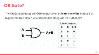
OR Gate?
The ORGate produces an HIGH output when at least one of its inputs is at
logic level HIGH. Here's what it looks like alongside it's truth table:
18
19.
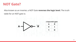
NOT Gate?
Also knownas an inverter, a NOT Gate reverses the logic level. The truth
table for an NOT gate is:
19
20.
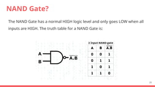
NAND Gate?
The NANDGate has a normal HIGH logic level and only goes LOW when all
inputs are HIGH. The truth table for a NAND Gate is:
20
21.
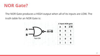
NOR Gate?
The NORGate produces a HIGH output when all of its inputs are LOW. The
truth table for an NOR Gate is:
21
22.
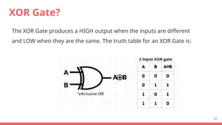
XOR Gate?
The XORGate produces a HIGH output when the inputs are different
and LOW when they are the same. The truth table for an XOR Gate is:
22
23.
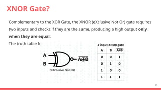
XNOR Gate?
Complementary tothe XOR Gate, the XNOR (eXclusive Not Or) gate requires
two inputs and checks if they are the same, producing a high output only
when they are equal.
The truth table for an XNOR Gate is:
23