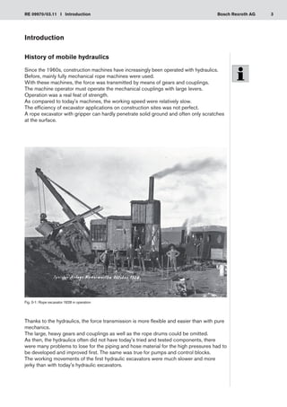
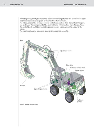
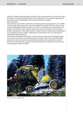
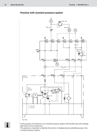
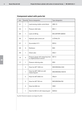
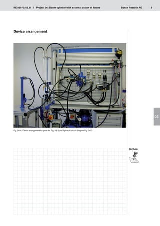
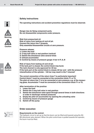
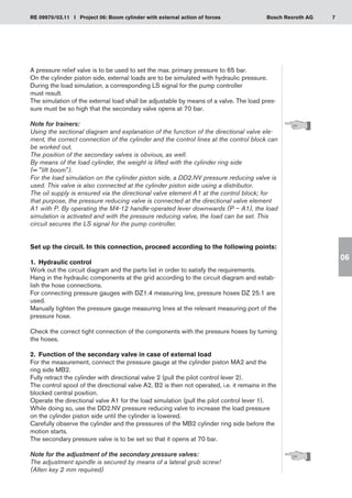
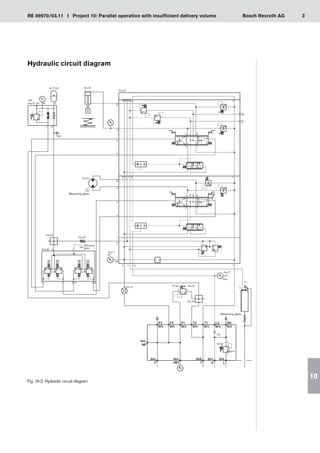
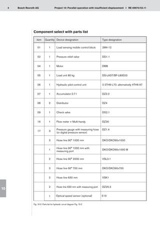
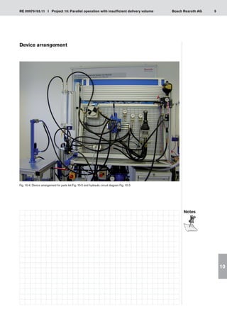
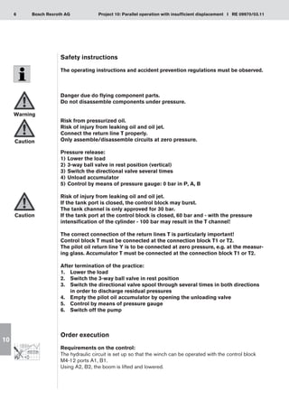
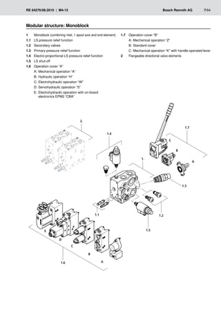
This document provides an introduction to mobile hydraulics and the knowledge transfer through project works. It discusses the history of mobile hydraulics in construction machines and how hydraulics replaced mechanical rope machines. It describes the open hydraulic circuit used for working equipment and multiple actuators. The document outlines the 6 steps for completing project works: information, planning, decision-making, execution, checks, and evaluation. It provides safety instructions and emphasizes that works should only be done by qualified personnel.


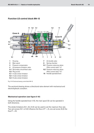

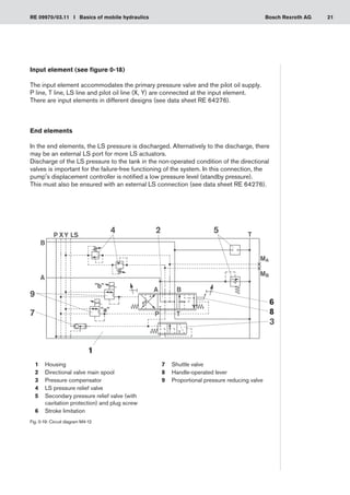
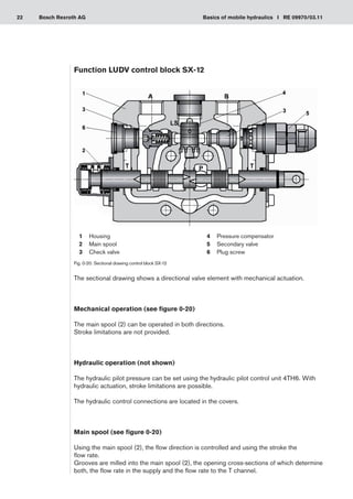


![Centrifugal Pumps and Compressor.pdf [Autosaved].pptx](https://cdn.slidesharecdn.com/ss_thumbnails/centrifugalpumpsandcompressor-231230130527-d7bcfe39-thumbnail.jpg?width=640&height=640&fit=bounds)


