This document provides instructions for operating a cut-off machine. It discusses safety precautions, tools used, specifications of the machine, and procedures for cutting materials. Key points include:
- Safety precautions like keeping guards in place, wearing proper protective equipment, and disconnecting the machine when not in use.
- The machine is powered by electricity and has specifications like voltage requirements and maximum cutting dimensions.
- Cutting procedures involve securely fastening the material, doing a trial run of the cutting wheel, and slowly lowering the wheel onto the material while the machine is running.
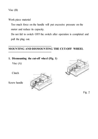
- Proper mounting and dismounting of the cutting wheel requires loosening and tightening a bolt using the provided wrench.


![56
wish to check the data traffic on the busses between the processor cores, which requires very low-
level debugging, at signal/bus level, with a logic analyzer, for instance.
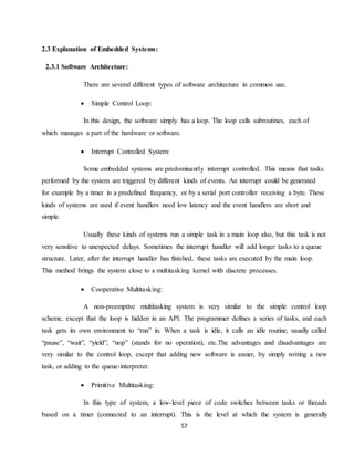
2.2.2 Reliability:
Embedded systems often reside in machines that are expected to run continuously for
years without errors and in some cases recover by themselves if an error occurs. Therefore the
software is usually developed and tested more carefully than that for personal computers, and
unreliable mechanical moving parts such as disk drives, switches or buttons are avoided.
Specific reliability issues may include:
The system cannot safely be shut down for repair, or it is too inaccessible to repair. Examples
include space systems, undersea cables, navigational beacons, bore-hole systems, and
automobiles.
The system must be kept running for safety reasons. "Limp modes" are less tolerable. Often
backups are selected by an operator. Examples include aircraft navigation, reactor control
systems, safety-critical chemical factory controls, train signals, engines on single-engine
aircraft.
The system will lose large amounts of money when shut down: Telephone switches, factory
controls, bridge and elevator controls, funds transfer and market making, automated sales and
service.
A variety of techniques are used, sometimes in combination, to recover from errors—
both software bugs such as memory leaks, and also soft errors in the hardware:
Watchdog timer that resets the computer unless the software periodically notifies the
watchdog
Subsystems with redundant spares that can be switched over to
software "limp modes" that provide partial function
Designing with a Trusted Computing Base (TCB) architecture[6] ensures a highly secure &
reliable system environment
An Embedded Hypervisor is able to provide secure encapsulation for any subsystem
component, so that a compromised software component cannot interfere with other
subsystems, or privileged-level system software. This encapsulation keeps faults from
propagating from one subsystem to another, improving reliability. This may also allow a
subsystem to be automatically shut down and restarted on fault detection.
Immunity Aware Programming](https://image.slidesharecdn.com/360degreesteering-220510035238-9006cc4a/85/360-degree-steering-doc-56-320.jpg)


![95
3.5 BLUE TOOTH Module:
‘Bluetooth’, the short-range radio link technology designed to "connect" an array of devices
including mobile phones, PC’s, and PDA’s, and the strategic decisions that Motorola should make in
incorporating this nascent technology into its product portfolio. The purpose of this paper will be to
provide a high-level overview of the technology to the head of Motorola's Communications
Enterprise, and prepare this corporate officer to be strategically and functionally conversant in the
technology with subordinates that have direct responsibility for integrating Bluetooth into Motorola's
product lines. The first sections of the paper detail the background of the Bluetooth technology and its
associated Special-Interest Group, or SIG, (a conglomeration of firms that has sought to reduce
market uncertainty, thereby expediting the diffusion of Bluetooth devices). Bluetooth’s perceived
strengths over other wireless connectivity technologies are also discussed and some macro-level
threats that may impede Bluetooth diffusion are outlined. The remainder of the paper details potential
Bluetooth markets (in terms of consumer and corporate applications) and examines Motorola's current
Bluetooth product offerings (a cell phone battery and computer PCMCIA card each enabled with a
Bluetooth chip). Finally, the paper provides guidance for Motorola's Bluetooth application
development strategies regarding the applications outlined in the SIG's specifications, namely
emphasizing those applications that leverage existing complementary assets, and those that are critical
to Bluetooth adoption regardless of prior expertise.
Bluetooth is a wireless technology standard for exchanging data over short distances (using
short-wavelength UHF radio waves in the ISM band from 2.4 to 2.485 GHz) from fixed and mobile
devices, and building personal area networks (PANs). Invented by telecom vendorEricsson in 1994 it
was originally conceived as a wireless alternative to RS-232 data cables. It can connect several
devices, overcoming problems of synchronization. Bluetooth is managed by the Bluetooth Special
Interest Group (SIG), which has more than 20,000 member companies in the areas of
telecommunication, computing, networking, and consumer electronics.[5] Bluetooth was standardized
as IEEE 802.15.1, but the standard is no longer maintained. The SIG oversees the development of the](https://image.slidesharecdn.com/360degreesteering-220510035238-9006cc4a/85/360-degree-steering-doc-95-320.jpg)
![96
specification, manages the qualification program, and protects the trademarks. To be marketed as a
Bluetooth device, it must be qualified to standards defined by the SIG. A network of patents is
required to implement the technology, which is licensed only for that qualifying device.
Communication and connection
A master Bluetooth device can communicate with a maximum of seven devices in a piconet
(an ad-hoc computer network using Bluetooth technology), though not all devices reach this
maximum. The devices can switch roles, by agreement, and the slave can become the master (for
example, a headset initiating a connection to a phone will necessarily begin as master, as initiator of
the connection; but may subsequently prefer to be slave).
The Bluetooth Core Specification provides for the connection of two or more piconets to form
a scatternet, in which certain devices simultaneously play the master role in one piconet and the slave
role in another.
At any given time, data can be transferred between the master and one other device (except for
the little-used broadcast mode. The master chooses which slave device to address; typically, it
switches rapidly from one device to another in a round-robin fashion. Since it is the master that
chooses which slave to address, whereas a slave is (in theory) supposed to listen in each receive slot,
being a master is a lighter burden than being a slave. Being a master of seven slaves is possible; being
a slave of more than one master is difficult. The specification is vague as to required behavior in
scatternets. Many USB Bluetooth adapters or "dongles" are available, some of which also include
an IrDAadapter
Specifications and features
The Bluetooth specification was developed as a cable replacement, initiated by Nils Rydbeck
in 1994, first specification written by Tord Wingren and developed by Jaap Haartsen and Sven
Mattisson, who were working for Ericsson in Lund, Sweden. The specification is based on frequency-
hopping spread spectrum technology.
The specifications were formalized by the Bluetooth Special Interest Group (SIG). The SIG was
formally announced on 20 May 1998. Today it has a membership of over 20,000 companies
worldwide.[36] It was established by Ericsson, IBM, Intel, Toshiba and Nokia, and later joined by
many other companies.
All versions of the Bluetooth standards are designed for downward compatibility. That lets the latest
standard cover all older versions.
The Bluetooth Core Specification Working Group (CSWG) produces mainly 4 kinds of specifications
The Bluetooth Core Specification, release cycle is typically a few years in between](https://image.slidesharecdn.com/360degreesteering-220510035238-9006cc4a/85/360-degree-steering-doc-96-320.jpg)
![97
Core Specification Addendum (CSA), release cycle can be as tight as a few times per year
Core Specification Supplements (CSS), can be released very quickly
Errata
Bluetooth v1.0 and v1.0B[
Versions 1.0 and 1.0B had many problems, and manufacturers had difficulty making their products
interoperable. Versions 1.0 and 1.0B also included mandatory Bluetooth hardware device address
(BD_ADDR) transmission in the Connecting process (rendering anonymity impossible at the protocol
level), which was a major setback for certain services planned for use in Bluetooth environments.
Bluetooth v1.1
Ratified as IEEE Standard 802.15.1–2002[37]
Many errors found in the 1.0B specifications were fixed.
Added possibility of non-encrypted channels.
Received Signal Strength Indicator (RSSI).
Bluetooth v1.2
Major enhancements include the following:
Faster Connection and Discovery
Adaptive frequency-hopping spread spectrum (AFH), which improves resistance to radio
frequency interference by avoiding the use of crowded frequencies in the hopping sequence.
Higher transmission speeds in practice, up to 721 kbit/s,[38] than in v1.1.
Extended Synchronous Connections (eSCO), which improve voice quality of audio links by
allowing retransmissions of corrupted packets, and may optionally increase audio latency to provide
better concurrent data transfer.
Host Controller Interface (HCI) operation with three-wire UART.
Ratified as IEEE Standard 802.15.1–2005[39]
Introduced Flow Control and Retransmission Modes for L2CAP.
Bluetooth v2.0 + EDR
This version of the Bluetooth Core Specification was released in 2004. The main difference is the
introduction of an Enhanced Data Rate (EDR) for faster data transfer. The nominal rate of EDR is
about 3 Mbit/s, although the practical data transfer rate is 2.1 Mbit/s. EDR uses a combination
of GFSK and Phase Shift Keying modulation (PSK) with two variants, π/4-DQPSKand
8DPSK.[40] EDR can provide lower power consumption through a reduced duty cycle.
The specification is published as "Bluetooth v2.0 + EDR" which implies that EDR is an optional
feature. Aside from EDR, there are other minor improvements to the 2.0 specification, and products](https://image.slidesharecdn.com/360degreesteering-220510035238-9006cc4a/85/360-degree-steering-doc-97-320.jpg)
![98
may claim compliance to "Bluetooth v2.0" without supporting the higher data rate. At least one
commercial device states "Bluetooth v2.0 without EDR" on its data sheet.
Bluetooth v2.1 + EDR
Bluetooth Core Specification Version 2.1 + EDR was adopted by the Bluetooth SIG on 26 July 2007.
The headline feature of 2.1 is secure simple pairing (SSP): this improves the pairing experience for
Bluetooth devices, while increasing the use and strength of security. See the section on Pairing below
for more details
2.1 allows various other improvements, including "Extended inquiry response" (EIR), which provides
more information during the inquiry procedure to allow better filtering of devices before connection;
and sniff subrating, which reduces the power consumption in low-power mode.
Bluetooth v3.0 + HS
Version 3.0 + HS of the Bluetooth Core Specification were adopted by the Bluetooth SIG on 21 April
2009. Bluetooth 3.0+HS provide theoretical data transfer speeds of up to 24 Mbit/s, though not over
the Bluetooth link itself. Instead, the Bluetooth link is used for negotiation and establishment, and the
high data rate traffic is carried over a collocated 802.11 link.
The main new feature is AMP (Alternative MAC/PHY), the addition of 802.11 as a high speed
transport. The High-Speed part of the specification is not mandatory, and hence only devices sporting
the "+HS" will actually support the Bluetooth over 802.11 high-speed data transfer. A Bluetooth 3.0
device without the "+HS" suffix will not support High Speed, and needs to only support a feature
introduced in Core Specification Version 3.0 or earlier Core Specification Addendum 1.
Uses
Class
Max. permitted power
Typ. range[14]
(m)
(mW) (dBm)
1 100 20 ~100
2 2.5 4 ~10
3 1 0 ~1
Bluetooth is a standard wire-replacement communications protocol primarily designed for low-power
consumption, with a short range based on low-cost transceiver microchips in each device. Because the](https://image.slidesharecdn.com/360degreesteering-220510035238-9006cc4a/85/360-degree-steering-doc-98-320.jpg)
![99
devices use a radio (broadcast) communications system, they do not have to be in visual line of sight
of each other, however a quasi optical wireless path must be viable.[5]Range is power-class-
dependent, but effective ranges vary in practice; see the table on the right.
Version Data rate Max. application throughput
1.2 1 Mbit/s >80 kbit/s
2.0 + EDR 3 Mbit/s >80 kbit/s
3.0 + HS 24 Mbit/s See Version 3.0 + HS
4.0 24 Mbit/s See Version 4.0 LE
The effective range varies due to propagation conditions, material coverage, production sample
variations, antenna configurations and battery conditions. Most Bluetooth applications are in indoor
conditions, where attenuation of walls and signal fading due to signal reflections will cause the range
to be far lower than the specified line-of-sight ranges of the Bluetooth products. Most Bluetooth
applications are battery powered Class 2 devices, with little difference in range whether the other end
of the link is a Class 1 or Class 2 device as the lower powered device tends to set the range limit. In
some cases the effective range of the data link can be extended when a Class 2 devices is connecting
to a Class 1 transceiver with both higher sensitivity and transmission power than a typical Class 2
device. Mostly however the Class 1 devices have a similar sensitivity to Class 2 devices. Connecting
two Class 1 devices with both high sensitivity and high power can allow ranges far in excess of the
typical 100m, depending on the throughput required by the application. Some such devices allow
open field ranges of up to 1 km and beyond between two similar devices without exceeding legal
emission limits.
While the Bluetooth Core Specification does mandate minimal for range, the range of the technology
is application-specific and not limited. Manufacturers may tune their implementations to the range
needed for individual use cases.
Bluetooth protocol stack](https://image.slidesharecdn.com/360degreesteering-220510035238-9006cc4a/85/360-degree-steering-doc-99-320.jpg)

![101
Replacement of previous wired RS-232 serial communications in test equipment, GPS
receivers, medical equipment, bar code scanners, and traffic control devices.
For controls where infrared was often used.
For low bandwidth applications where higher USB bandwidth is not required and cable-free
connection desired.
Sending small advertisements from Bluetooth-enabled advertising hoardings to other,
discoverable, Bluetooth devices.
Wireless bridge between two Industrial Ethernet (e.g., PROFINET) networks.
Three seventh and eighth generation game consoles, Nintendo's Wii and Sony’s PlayStation,
use Bluetooth for their respective wireless controllers.
Dial-up internet access on personal computers or PDAs using a data-capable mobile phone as
a wireless modem.
Short range transmission of health sensor data from medical devices to mobile phone, set-top
box or dedicated tele health devices.
Allowing a DECT phone to ring and answer calls on behalf of a nearby mobile phone.
Real-time location systems (RTLS), are used to track and identify the location of objects in
real-time using “Nodes” or “tags” attached to, or embedded in the objects tracked, and “Readers” that
receive and process the wireless signals from these tags to determine their locations.[25]
Personal security application on mobile phones for prevention of theft or loss of items. The
protected item has a Bluetooth marker (e.g., a tag) that is in constant communication with the phone.
If the connection is broken (the marker is out of range of the phone) then an alarm is raised. This can
also be used as a man overboard alarm. A product using this technology has been available since
2009.[26]
Calgary, Alberta, Canada's Roads Traffic division uses data collected from travelers' Bluetooth
devices to predict travel times and road congestion for motorists.[27]
Wireless transmission of audio, (a more reliable alternative to FM transmitters)
3.5.1 History
Bluetooth is a worldwide initiative spearheaded by some of the leading powerhouses in the
electronics industry, chiefly Ericsson, Intel, IBM, Nokia, and Toshiba. Following initial development
by Ericsson, these firms started the Bluetooth special-interest group in 1998 with the intent of
developing a worldwide technology for wireless communication among diverse devices. Bluetooth
enables wireless data and voice communication via a short-range radio to provide a low-cost solution](https://image.slidesharecdn.com/360degreesteering-220510035238-9006cc4a/85/360-degree-steering-doc-101-320.jpg)


![122
fixed; hence they have to be pre-calculated and stored by the controller. This dictates that the control
of four-wheel steering systems be very precise, and consequently, complex. This is another reason
why manufacturers have not preferred the use of such systems in their vehicles, even with recent
advances in technology. The cost of such systems can be high, and a good amount of research &
development is required upfront.[2]
Fig. Front wheel steering.[2]
Shorter Radius Turning:
To minimize the turning radius for the fixed-wheel, differential-drive configuration, the fixed-drive
wheels must be located as close as possible to the geometric center of the chair. For fixed front-wheel-
drive chairs, the drive wheels are moved rearward, and for fixed rear-wheel-drive chairs, the rear
wheels are moved forward. Another benefit of locating the drive wheels close to the geometric center
of the chair is that a larger portion of the total weight of the wheelchair is borne by the drive wheels
and less by the caster wheels. The greater the weight borne by the caster wheels, the more difficult it
is to change directions when caster wheels must reverse directions and rotate through 180°. The
approach, however, causes the designer to take extraordinary steps to provide stability. Typically,
stability is achieved by counterbalancing the user's mass over and in front of the main drive wheels
with the mass of the batteries behind the main drive wheels. It may be necessary to provide caster or
sprung wheels in the rear of the chair to avoid tipping backward while accelerating forward. The
addition of these extra wheels, if small, may also compromise the chair's ability to climb low
obstacles. An alternate approach to minimizing the turning radius is to steer all four wheels; this
avoids the problems associated with caster wheels, yet retains minimum turning radius and maximizes
stability. Added benefits of four-wheel steering are the tracking of front and rear wheels along the
same path and enhanced obstacle climbing capability. The challenge in designing a mechanical four-
wheel steering mechanism is to design a device with the ability to turn each wheel through 180° while
minimizing Ackerman errors (misalignment of the wheels). Ackerman steering linkages, such as those
used in automobiles, owe their simple design to the relatively small turning angles required by that
type of vehicle. For highly maneuverable wheelchairs, the range of steering angle is much greater, and
the wheels must maintain proper alignment over that entire range to avoid undesirable scrubbing
when the wheelchair moves. Scrubbing results in excessive tire wear, wrinkling of carpets, and/or
undesirable tire noise.[2]](https://image.slidesharecdn.com/360degreesteering-220510035238-9006cc4a/85/360-degree-steering-doc-122-320.jpg)
![123
Fig. Shorter radius turning.[2]
Parallel Parking:
Zero steer can be significantly easy for the parking process, due to its extremely short turning
footprint. This is exemplified by the parallel parking scenario, which is common in foreign countries
and is pretty relevant to our cities. Here, a car has to park between two other cars parked on the
service lane. This maneuver requires a three-way movement of the vehicle and consequently heavy
steering inputs. Moreover, to successfully park the vehicle without incurring any damage, at least 1.75
times the length of the car must be available for parking for a two-wheel steered car. The car requires
just about the same length as itself to park in the spot in the case of parallel parking. The vehicle will
slide to the parking line at a specific angle to the wheels. Also the rear wheels will be parallel to the
front wheels.[2]
Fig: Parallel Parking[2]](https://image.slidesharecdn.com/360degreesteering-220510035238-9006cc4a/85/360-degree-steering-doc-123-320.jpg)
![124
Zero Degree Rotation:
This vehicle has all the four modes of steering described above, though it sports a truly complex
drive-train and steering layout with two transfer cases to drive the left and right wheels separately.
The four wheels have fully independent steering and need to turn in an unconventional direction to
ensure that the vehicle turns around on its own axis. Such a system requires precise calculation to
make certain that all three steering modes function perfectly. The 360 degree rotation mode of 4WS is
applied by chain movement which helps in movement of wheels in the required position. The
movement of wheels are in a way that the vehicle will move or turn in 360 degree. Also since the 360
degree mode does not require steering inputs the driver can virtually park the vehicle without even
touching the steering wheel. All he has to do give throttle and brake inputs and even they can be
automated in modern cars. Hence such a system can even lead to vehicles that can drive and park by
themselves.[2]
Fig. Zero Degree Rotation[2]](https://image.slidesharecdn.com/360degreesteering-220510035238-9006cc4a/85/360-degree-steering-doc-124-320.jpg)
![125
2.4 4-BAR LINK MECHANISM:
A four-bar linkage, also called a four-bar, is the simplest movable closed chain linkage. It consists
of four bodies, called bars or links, connected in a loop by four joints. Generally, the joints are
configured so the links move in parallel planes, and the assembly is called a planar four-bar
linkage.[1]
If the linkage has four hinged joints with axes angled to intersect in a single point, then the links move
on concentric spheres and the assembly is called a spherical four-bar linkage. Bennett's linkage is a
spatial four-bar linkage with hinged joints that have their axes angled in a particular way that makes
the system movable.[2][3]
Planar four-bar linkage
Planar four-bar linkages are constructed from four links connected in a loop by four one degree of
freedom joints. A joint may be either a revolute, that is a hinged joint, denoted by R, or a prismatic, as
sliding joint, denoted by P.
A link connected to ground by a hinged joint is usually called a crank. A link connected to ground by
a prismatic joint is called a slider. Sliders are sometimes considered to be cranks that have a hinged
pivot at an extremely long distance away perpendicular to the travel of the slider.
The link that connects two cranks is called a floating link or coupler. A coupler that connects a crank
and a slider, it is often called a connecting rod.
There are three basic types of planar four-bar linkage depending on the use of revolute or prismatic
joints:
1. Four revolute joints: The planar quadrilateral linkage is formed by four links and
four revolute joints, denoted RRRR. It consists of two cranks connected by a coupler.
2. Three revolute joints and a prismatic joint: The slider-crank linkage is constructed from four
links connected by three revolute and one prismatic joint, or RRRP. It can be constructed with
crank and a slider connected by the connecting rod. Or it can be constructed as a two cranks
with the slider acting as the coupler, known as an inverted slider-crank.
3. Two revolute joints and two prismatic joints: The double slider is a PRRP linkage.[3] This
linkage is constructed by connecting two sliders with a coupler link. If the directions of
movement of the two sliders are perpendicular then the trajectories of the points in the coupler
are ellipses and the linkage is known as an elliptical trammel, or the Trammel of Archimedes.](https://image.slidesharecdn.com/360degreesteering-220510035238-9006cc4a/85/360-degree-steering-doc-125-320.jpg)
![126
Planar four-bar linkages are important mechanisms found in machines.
The kinematics and dynamics of planar four-bar linkages are important topics in mechanical
engineering.
Planar four-bar linkages can be designed to guide a wide variety of movements.
Planar one degree-of-freedom linkages[edit]
The mobility formula provides a way to determine the number of links and joints in a planar linkage
that yields a one degree-of-freedom linkage. If we require the mobility of a planar linkage to be M=1
and fi=1, the result is
or
This formula shows that the linkage must have an even number of links, so we have
N=2, j=1: this is a two-bar linkage known as the lever;
N=4, j=4: this is the four-bar linkage;
N=6, j=7: this is a six-bar linkage [ it has two links that have three joints, called ternary
links, and there are two topologies of this linkage depending how these links are
connected. In the Watt topology, the two ternary links are connected by a joint. In the
Stephenson topology the two ternary links are connected by binary links;[15]
N=8, j=10: the eight-bar linkage has 16 different topologies;
N=10, j=13: the 10-bar linkage has 230 different topologies,
N=12, j=16: the 12-bar has 6856 topologies.
See Sunkari and Schmidt[16] for the number of 14- and 16-bar topologies, as well as the
number of linkages that have two, three and four degrees-of-freedom.
The planar four-bar linkage is probably the simplest and most common linkage. It is a one
degree-of-freedom system that transforms an input crank rotation or slider displacement into
an output rotation or slide.](https://image.slidesharecdn.com/360degreesteering-220510035238-9006cc4a/85/360-degree-steering-doc-126-320.jpg)
![127
Types of four-bar linkages, s = shortest link, l = longest link
Examples of four-bar linkages are:
the crank-rocker, in which the input crank fully rotates and the output link rocks back and
forth;
the slider-crank, in which the input crank rotates and the output slide moves back and
forth;
drag-link mechanisms, in which the input crank fully rotates and drags the output crank in
a fully rotational movement.
Planar quadrilateral linkage
Planar quadrilateral linkage, RRRR or 4R linkages have four rotating joints. One link of the chain is
usually fixed, and is called the ground link, fixed link, or the frame. The two links connected to the
frame are called the grounded links and are generally the input and output links of the system,
sometimes called the input link and output link. The last link is the floating link, which is also called
a coupler or connecting rod because it connects an input to the output.
Assuming the frame is horizontal there are four possibilities for the input and output links:[3]
A crank: can rotate a full 360 degrees
A rocker: can rotate through a limited range of angles which does not include 0° or 180°
A 0-rocker: can rotate through a limited range of angles which includes 0° but not 180°
A π-rocker: can rotate through a limited range of angles which includes 180° but not 0°
Some authors do not distinguish between the types of rocker
Grashof condition
The Grashof condition for a four-bar linkage states: If the sum of the shortest and longest link of a
planar quadrilateral linkage is less than or equal to the sum of the remaining two links, then the](https://image.slidesharecdn.com/360degreesteering-220510035238-9006cc4a/85/360-degree-steering-doc-127-320.jpg)
![128
shortest link can rotate fully with respect to a neighboring link. In other words, the condition is
satisfied if S+L ≤ P+Q where S is the shortest link, L is the longest, and P and Q are the other links.
Design of four bar mechanisms
The synthesis, or design, of four bar mechanisms is important when aiming to produce a desired
output motion for a specific input motion. In order to minimize cost and maximize efficiency, a
designer will choose the simplest mechanism possible to accomplish the desired motion. When
selecting a mechanism type to be designed, link lengths must be determined by a process called
dimensional synthesis. Dimensional synthesis involves an iterate-and-analyze methodology which in
certain circumstances can be an inefficient process; however, in unique scenarios, exact and detailed
procedures to design an accurate mechanism may not exist.[6]
Time ratio[edit]
The time ratio (Q) of a four bar mechanism is a measure of its quick return and is defined as
follows:[6]
With four bar mechanisms there are two strokes, the forward and return, which when added together
create a cycle. Each stroke may be identical or have different average speeds. The time ratio
numerically defines how fast the forward stroke is compared to the quicker return stroke. The total
cycle time (Δtcycle) for a mechanism is:[6]
Most four bar mechanisms are driven by a rotational actuator, or crank, that requires a specific
constant speed. This required speed (ωcrank)is related to the cycle time as follows:[6]
Some mechanisms that produce reciprocating, or repeating, motion are designed to produce
symmetrical motion. That is, the forward stroke of the machine moves at the same pace as the return
stroke. These mechanisms, which are often referred to as in-line design, usually do work in both
directions, as they exert the same force in both directions.[6]
Examples of symmetrical motion mechanisms include:](https://image.slidesharecdn.com/360degreesteering-220510035238-9006cc4a/85/360-degree-steering-doc-128-320.jpg)
![129
Windshield wipers
Engine mechanisms or pistons
Automobile window crank
Other applications require that the mechanism-to-be-designed has a faster average speed in one
direction than the other. This category of mechanism is most desired for design when work is only
required to operate in one direction. The speed at which this one stroke operates is also very important
in certain machine applications. In general, the return and work-non-intensive stroke should be
accomplished as fast as possible. This is so the majority of time in each cycle is allotted for the work-
intensive stroke. These quick-return mechanisms are often referred to as offset.[6]
Examples of offset mechanisms include:
Cutting machines
Package-moving devices
With offset mechanisms, it is very important to understand how and to what degree the offset affects
the time ratio. To relate the geometry of a specific linkage to the timing of the stroke, an imbalance
angle (β) is used. This angle is related to the time ratio, Q, as follows:[6]
Through simple algebraic rearrangement, this equation can be rewritten to solve for β:[6]
Timing charts[edit]
Timing charts are often used to synchronize the motion between two or more mechanisms. They
graphically display information showing where and when each mechanism is stationary or performing
its forward and return strokes. Timing charts allow designers to qualitatively describe the
required kinematic behavior of a mechanism.[6]
These charts are also used to estimate the velocities and accelerations of certain four bar links. The
velocity of a link is the time rate at which its position is changing, while the link's acceleration is the
time rate at which its velocity is changing. Both velocity and acceleration are vector quantities, in that
they have both magnitude and direction; however, only their magnitudes are used in timing charts.
When used with two mechanisms, timing charts assume constant acceleration. This assumption](https://image.slidesharecdn.com/360degreesteering-220510035238-9006cc4a/85/360-degree-steering-doc-129-320.jpg)
![130
produces polynomial equations for velocity as a function of time. Constant acceleration allows for the
velocity vs. time graph to appear as straight lines, thus designating a relationship
between displacement (ΔR), maximum velocity (vpeak), acceleration (a), and time(Δt). The following
equations show this.[6][7]
ΔR = vpeakΔt
ΔR = a(Δt)^2
Given the displacement and time, both the maximum velocity and acceleration of each
mechanism in a given pair can be calculated.[6]
A planar four-bar linkage consists of four rigid rods in the plane connected by pin joints. We call the
rods:
Ground link gg: fixed to anchor pivots AA and BB.
Input link aa: driven by input angle αα.
Output link bb: gives output angle ββ.
Floating link ff: connects the two moving pins CC and DD.
We often think of a four-bar linkage as being driven at the input angle αα, resulting in the output
angle ββ. We only need one input, because the system has exactly NDOF=1NDOF=1 degree of
freedom. We can count the DOF as 9 free variables (three moving rigid bodies with three variables
each) minus 8 constraints (four pin joints with two constraints each).](https://image.slidesharecdn.com/360degreesteering-220510035238-9006cc4a/85/360-degree-steering-doc-130-320.jpg)


![134
Chapter 5
5.1 Result:
The project “FOUR WHEEL STEERING SYSTEM” was designed such that the
robot can be operated using a battery, Microcontroller, Bluetooth, dc motors and L293D drivers
5.2 Conclusion:
Four wheel steering is a relatively new technology, that imposes maneuverability in
cars, trucks and trailers .in standard two wheels steering vehicles, the rear set of wheels are always
directed forward therefore and do not play an active role in controlling the steering in four wheel
steering system the rear wheel can turn left and right . To keep the driving controls as simple as
possible. The aim of 4 Wheel Steering system is a better stability during overtaking manoeuvres,
reduction of vehicle oscillation around its vertical axis, reduced sensibility to lateral wind, neutral
behaviour during cornering, etc., i.e. improvement of active safety
References
[1] Unknown, Four wheel steering report, http://www.scribd.com/doc/34677964/FourWheel-Steering-report,
Retrived on 13th Sep 2012.
[2] Unknown, Four wheel steering, http://www.wisegeek.com/what-is-four-wheelsteering.htm, Retrived on
13th Sep 2012.
[3] Unknown, Four wheel steering, http://what-whenhow.com/automobile/four-wheel-steering-4wsautomobile/,
Retrived on 14th Sep 2012.
[4] “Honda Prelude Si 4WS: It Will Never Steer You Wrong,” Car and Driver, Vol. 33, No. 2, pps. 40- 45,
August 1987.
[5] Sano s et al, “Operational and design features of the steer angle dependent four wheel steering system.”
11th International conference on Experimental safety vehicles, Washington D C 1988, 5P.
[6] Jack Erjavec., Automotive Technology, A System Approach, 5th Edition, 2010.](https://image.slidesharecdn.com/360degreesteering-220510035238-9006cc4a/85/360-degree-steering-doc-134-320.jpg)
![135
[7] Farrokhi, Four wheel steering, http://www.iust.ac.ir/files/ee/farrokhi_0a5f0/journa l_papers/j13.pdf,
Retrived on 20th Oct 2012.
[8] M. Abe, "Vehicle Dynamics and Control for Improving Handling and Active Safety: From Four-Wheel-
Steering to Direct Yaw Moment Control," in Proc. Institution of Mechanical Engineers, Part K, Journal of
Milti-body Dynamics, vol. 213, no. 4, 1999.
[9] Lee, A.Y., “Vehicle Stability Augmentation Systems Designs for Four Wheel Steering Vehicles,” ASME
Journal of Dynamical Systems, Measurements and Control, Vol. 112, No. 3, pps. 489-495, September 1990.
[10] four wheel steering system for future - International Journals tjprc.org/download.php?fname=2-
23...5...%20FOUR%20%20...
[11] Nalecz A G and Bindemann A C, “ Analysis of the dynamic response of four wheel steering vehicles at
high speed.” International journal of vehicle design, Vol 9, No 2, 1988, pp. 179-202.
[12] Unkown, Maruti Suzuki, http://www.carfolio/maruti-suzuki-800.htm, Retrived on 4th Nov 2012.
[13] Reza.N.Jazar., Vehicle Dynamics, Theory and applications, 2008.](https://image.slidesharecdn.com/360degreesteering-220510035238-9006cc4a/85/360-degree-steering-doc-135-320.jpg)


