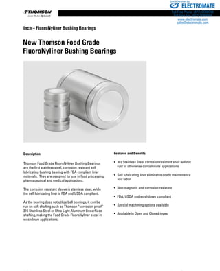
Download to read offline


![96 www.thomsonlinear.com
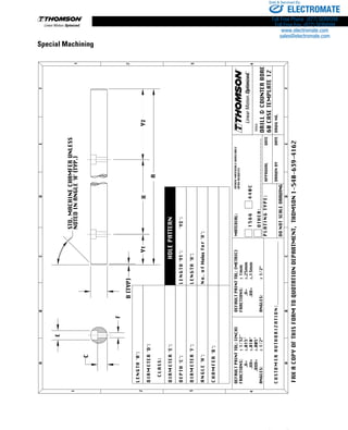
Inch – XR Ball Bushing Bearings
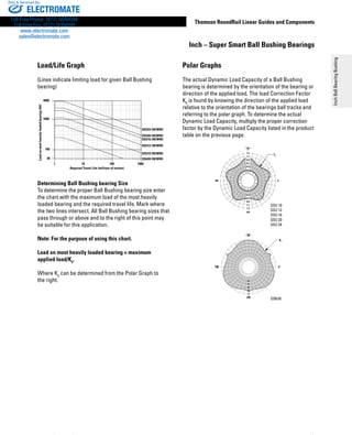
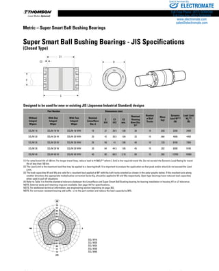
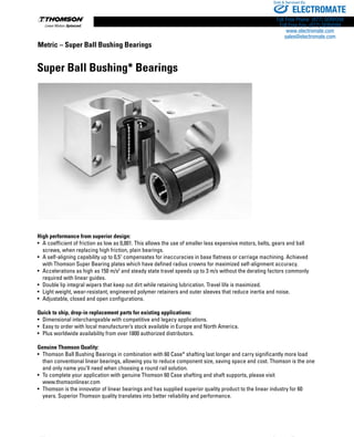
X-Y-Z System
Objective
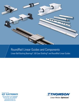
Build a rigid X-Y-Z System designed to perform welding and flame cutting tasks.
Solution
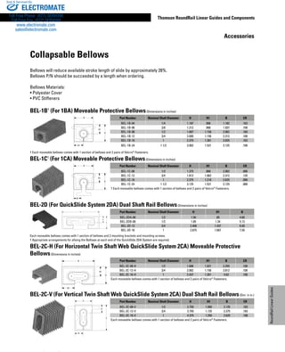
Extra Rigid Ball Bushing Bearings will be used on the X-axis to minimize deflection of the cantilevered Y-axis. Self-
aligning Super Smart Ball Bushing Bearings are used on the Y and Z axis to simplify the assembly.
Products Specified
X-axis
4 - XR-32-OPN (XR Ball Bushing Bearing)
2 - XSRA-32 x 108 in (60 Case LinearRace Support Rail Assembly)
Y-axis
4 - SSU-12-OPN (Super Smart Ball Bushing Bearing [Open Type])
2 - LSR-12-PD x 48 in (Low Profile 60 Case LinearRace Support Rail)
2 - 3/4 L PD CTL x 48 in (60 Case LinearRace)
Z-axis
4 - SSU-12 (Super Smart Ball Bushing Bearing)
2 - 3/4 L CTL x 36 in (60 Case LinearRace)
Benefits
The high load capacity, rigidity and RoundRail Advantage of the Super Smart and XR Ball Bushing Bearings provided an
easy to assemble system with a repeatability of ±.005 in.
SSU-12
XR-32-OPN
SSU-12-OPN
ELECTROMATE
Toll Free Phone (877) SERVO98
Toll Free Fax (877) SERV099
www.electromate.com
sales@electromate.com
Sold Serviced By:](https://image.slidesharecdn.com/thomsonroundraillinearguidescatalog-170503181353/85/Thomson-RoundRail-Linear-Guides-96-320.jpg)


![279
Thomson RoundRail Linear Guides and Components
Engineering
www.thomsonlinear.com
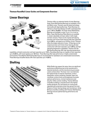
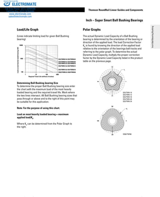
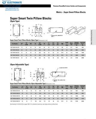
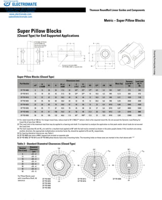
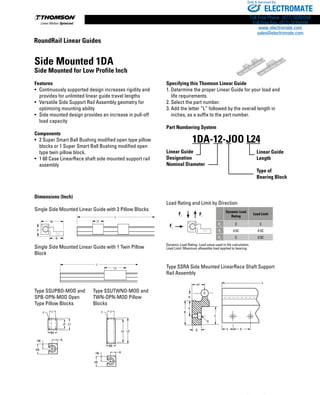
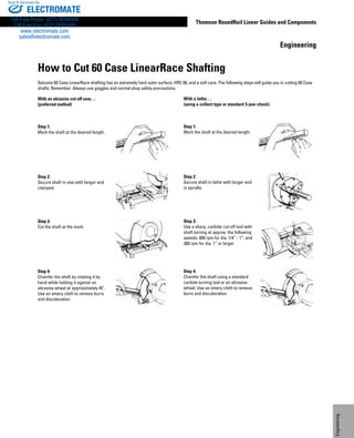
Installation Guidelines
Thomson Ball Bushing bearings are manufactured to exceptionally close tolerances and offer
smooth, virtually friction-free motion. The performance features of the bearings will only be
realized, however, if care is taken during
their installation.
Two areas of primary importance are the bearings alignment and the shaft parallelism. Two
bearings are normally used on each shaft to assure smooth operation. The housing should be
carefully aligned using the method given below. If a single twin-type housing is used, these
procedures are not necessary. It is also necessary to assure that the height from the housing
mounting surface to the shaft is consistent within .001 inch. Shimming may be necessary
depending on the accuracy of the mounting surfaces to which the housings are bolted.
The housing can be mounted to the plate using the following procedure:
a. Prepare the carriage plate with one side having an abutting surface.
b. Mount two housings with the reference edges located against the abutting surface and
tighten the hold down bolts. Figure #1
c. Mount the second pair of housings on the opposite side of the carriage and tighten the bolts
finger tight.
d. Insert a location shaft of correct diameter and tolerance (h6) through these two housings and
reference the distance from the abutting surface in [b] above, to this locating shaft. Figure #2
e. After appropriate alignment of this pair of housings, tighten bolts to secure housings to
carriage.
After the carriage is properly prepared, the shafts must be mounted to the surface. To achieve
smooth, accurate motion, the shafts must be mounted parallel within .001 inch over the length of
the stroke. This can be done by using the following procedure:
a. Mount one shaft (either end-supported or fully supported) to the surface with mounting bolts
finger tight.
b. Using an aligning device such as a laser, auto-collimator or other optics, sight the shaft
straight and secure to mounting surface.
c. After this first shaft is fixed, the second shaft can be positioned and held down with bolts
finger tight.
d. The carriage is then mounted and its movement will pull this second shaft parallel to the first.
Figures #3 and #4
e. If the second shaft is then secured into position, the procedure is complete. Note that for fully
supported systems, this securing should be done when the carriage is close to the bolts. For
end supported systems, the securing should be done when the carriage is at the ends of the
shafts. Figure #5
f. An additional check can be done at this time to assure that the carriage is tracking correctly
(i.e., that the carriage edge is moving parallel to the shaft). An indicator touching the carriage
edge should not vary, as the carriage is moved along the shafts. Figure #6
Figure 1
Figure 2
Figure 3
Figure 4
Figure 5
Figure 6
Engineering
ELECTROMATE
Toll Free Phone (877) SERVO98
Toll Free Fax (877) SERV099
www.electromate.com
sales@electromate.com
Sold Serviced By:](https://image.slidesharecdn.com/thomsonroundraillinearguidescatalog-170503181353/85/Thomson-RoundRail-Linear-Guides-279-320.jpg)


This document provides an overview of Thomson RoundRail Linear Guides and Components. It describes Thomson's linear bearing products including Super Smart Ball Bushing Bearings, Pillow Blocks, Precision Steel Ball Bushing Bearings, XR Extra Rigid Ball Bushing Bearings, RoundWay Linear Roller Bearings, and FluoroNyliner Bushing Bearings. It also discusses 60 Case LinearRace shafting and RoundRail Linear Guides. The document is an overview of Thomson's extensive product line of linear motion components.


