Download to read offline
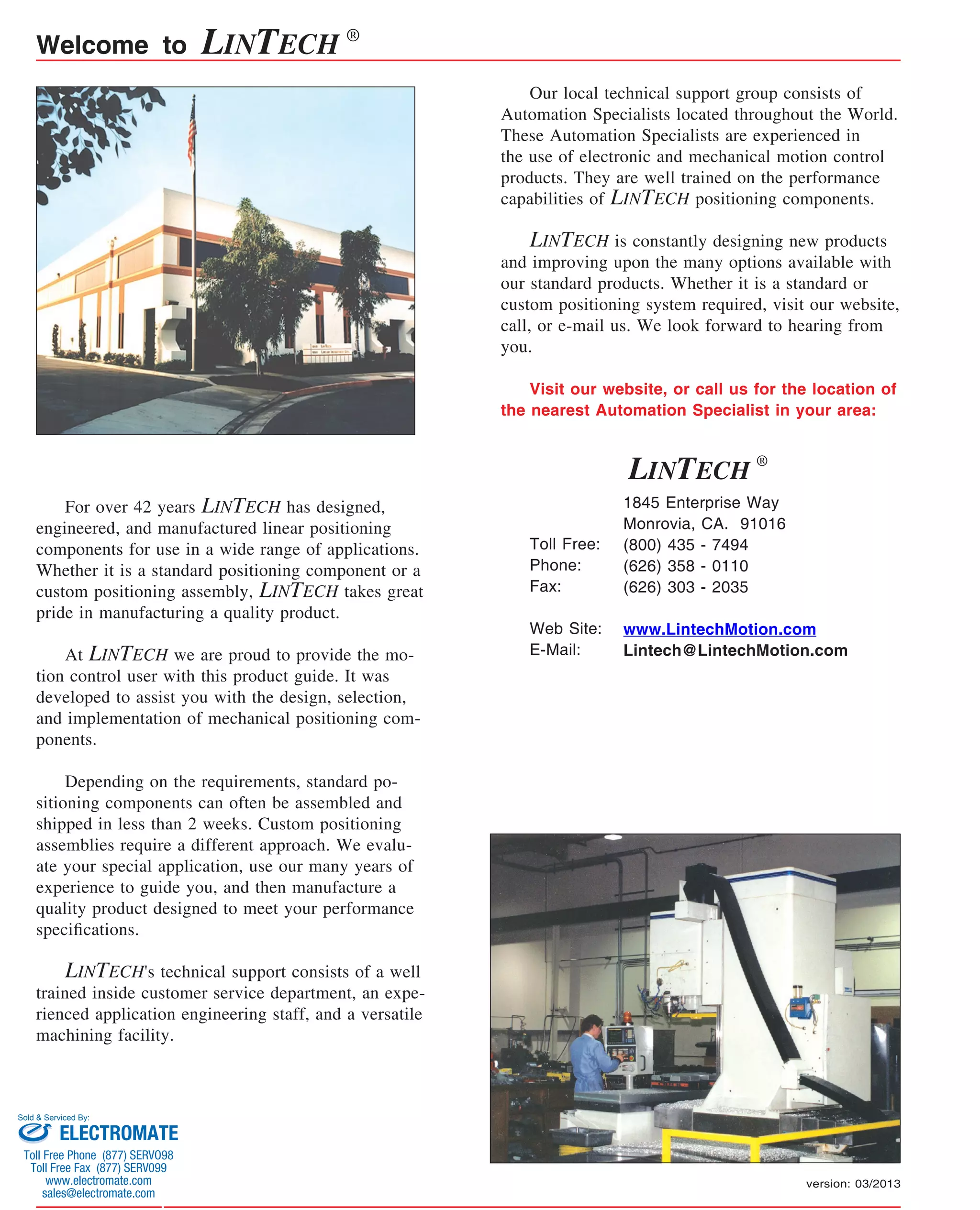

LINTECH has over 42 years of experience designing and manufacturing linear positioning components. They produce both standard and custom positioning systems using their technical expertise. LINTECH prides itself on producing high quality products with short lead times on standard components. They support customers with application engineering and local technical specialists.


