The Codex of Business Writing Software for Real-World Solutions 2.pptx
Lintech 170series specsheet
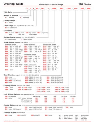
1. Ordering Guide Screw Drive - 6 inch Carriage 170 Series
170 Series Ordering
Guide
Table Series
Number of Bearings
2 - 2 bearings 4 - 4 bearings
Carriage Length
6 - 6 inches
06 - 3 to 60 inches
Cover Plate
17 2 6 06 - CP1
CP0 - no cover
plates
CP1- top cover
plate only
CP2 - top & side
Screw Options (see pages E-30 to E-35)
cover plates
Rolled ball screws
S007 - .625 x .200 NPL(T)
S008 - .625 x .200 PL(T) S020 - .750 x .500 PL(T)
S009 -
S010 -
.625 x 1.000 NPL
.625 x 1.000 PL
S011 - .625 x 1.000 NPL(T)
Rolled ball screws
Ground ball screws
S213 - .625 x .500 PL
Rolled acme screws
S301 -
S012 - .625 x 1.000 PL(T)
M00 - none
M01 - hand crank
M03 - NEMA 23 mount (M)
Coupling Options (see pages E-66 to E-67)
Limit & Home Switches (see pages E-63 to E-65)
EOT & home switches
EOT switches only
L00 - no switches
home switch only
Encoder Options (see page E-71)
E00 - none
E01 - rotary (500 lines/rev)
Power-off Brakes (see page E-70)
Specifications subject to change without notice
- 1 - - M02 - C155 - L01 - E00 - B00
Precision ball screws
S114
S115
S116
S119
S122
S123
S124
M06 - NEMA 23 (RH) wrap
M08 - NEMA 34 (RH) wrap
Mechanical Reed Hall
L01
L02
L03
E02 - rotary (1000 lines/rev)
E03 - rotary (1270 lines/rev)
L04
L05
L06
Prox (NPN)
Prox (PNP)
E10 - linear (2500 lines/inch) E99 - other
B00 - none B01 - 24 VDC B02 - 90 VDC B99 - other
L07
L08
L09
L10
L11
L12
L99 - other
E11 - linear (125 lines/mm)
Motor Mount (see pages E-11, E-13, E-15, E-17, E-68 & E-69)
(E) - English Interface
(LH) - Left Hand
(M) - Metric Interface
(NPL) - Non Preloaded
(PL) - Preloaded
(RH) - Right Hand
(T) - Turcite Nut
S005
L13
L14
L15
Travel Length (see pages E-10, E-12, E-14 & E-16)
Carriage Inserts (see pages E-11, E-13, E-15 & E-17)
WC1 - waycovers
1 - English mount 2 - Metric mount
S005 - .625 x .200 NPL
S006 -
S013 -
S014 -
.625 x .200 PL
.750 x .200 NPL
.750 x .200 PL
S015 - .750 x .200 NPL(T)
S999 - other
S017 -
S018 -
.750 x .500 NPL
.750 x .500 PL
S019 - .750 x .500 NPL(T)
- .625 x .200 NPL
-
-
-
-
-
.625 x .200 PL
16 x 5 NPL
16 x 5 PL
16 x 10 NPL
16 x 10 PL
-
16 x 16 NPL
-
16 x 16 PL
S117
S118
S120
S121
- .750 x .200 NPL
-
.750 x .200 PL
-
20 x 5 NPL
-
20 x 5 PL
-
20 x 20 NPL
-
20 x 20 PL
S125
S128
S129
- .625 x .200 PL
-
-
16 x 5 PL
16 x 16 PL
.625 x .100 NPL
.625 x .100 PL
.625 x .200 NPL
.625 x .200 PL
S212
S214
S215
-
-
-
S300
S302
S303
S016 - .750 x .200 PL(T)
other
M02 - NEMA 23 mount (E)
M04 - NEMA 34 mount (E)
M07 -
M09 -
NEMA 23 (LH) wrap
M99 - NEMA 34 (LH) wrap
M05 - NEMA 34 mount (M)
M20 to M98 - see Website
C000 - none C025 to C030 - C100
C048 to C069 - C125
C130 to C136 - H100
C155 to C184 - H131
C407 to C415 - G100
C999 - other C435 to C464 - G126
C197 to C199 - H163 C470 to C480 - G158
2. Technical Reference Screw Drive - 6 inch Carriage 170 Series
Load Capacities Two (2) Bearing Carriage Four (4) Bearing Carriage
7,780 lbs
2,090 lbs
11,660 lbs
1,025 ft-lbs
275 ft-lbs
1,830 ft-lbs
930 ft-lbs
250 ft-lbs
1,670 ft-lbs
1,945 lbs
525 lbs ( 238 kgf) 525 lbs ( 238 kgf)
lbs
895 lbs
( 3530
137 ( 185
( 948
( 5290
240 lbs ( 109 kgf) 240 lbs ( 109 kgf)
772 in/sec2
kgf)
kgf)
kgf)
N-m)
N-m)
( 2480 N-m)
( 1260 N-m)
( 339 N-m)
( 2260 N-m)
( 882 kgf)
( 1320 kgf)
( 406 kgf)
( 19,6 m/sec2)
d1 Center to center distance (spread) between the two rails 3.660 in ( 92,96 mm) 3.660 in mm)
( 92,96
( 83,57
Table Material Base, Carriage, End Plates, & Cover Plate option - 6061 anodized aluminum
Linear Rail Material
Case Hardened Steel
Acme Screw - Stainless Steel
Rolled Ball, Precision Ball, & Ground Ball - Case Hardened Steel
(<
(<
4,06
4,06
microns/25mm)
microns/25mm)
Screw Material (see pages E-30 to E-35)
Orthogonality (multi-axis systems) < 30 arc-seconds
Friction Coefficient < 0.01
Motor Mount NEMA 23 & 34 Mounts, Metric Mounts, Motor Wraps, and Hand Crank Option
Coupling Three (3) different styles available
Specifications subject to change without notice
Specifications
Dynamic Horizontal 2 million inches (50 km) of travel
Dynamic Horizontal 50 million inches (1270 km) of travel
Static Horizontal
Dynamic Roll Moment 2 million inches (50 km) of travel
Dynamic Roll Moment 50 million inches (1270 km) of travel
Static Roll Moment
Dyn. Pitch & Yaw Moment 2 million inches (50 km) of travel
Dyn. Pitch & Yaw Moment 50 million inches (1270 km) of travel
Static Pitch & Yaw Moment
Each Bearing Dyn. Capacity 2 m illion inches (50 km) of travel
Each Bearing Dyn. Capacity 5 0 million inches (1270 km) of travel
Each Bearing Static Load Capacity
Thrust Force Capacity 10 million screw revolutions
Thrust Force Capacity 500 million screw revolutions
Maximum Acceleration
d2 Center to center distance (spacing) of the bearings on a single rail
dr Center distance of the bearing to top of carriage plate surface
3,890 lbs ( 1765 kgf)
1,045 lbs kgf)
5,830 lbs kgf)
510 ft-lbs ( 690 N-m)
ft-lbs N-m)
915 ft-lbs N-m)
71 ft-lbs ( 96 N-m)
19 ft-lbs ( 26 N-m)
126 ft-lbs ( 170 N-m)
1,945 lbs ( 882 kgf)
2,910 lbs ( 1320 kgf)
895 lbs ( 406 kgf)
386 in/sec2
( 9,8 m/sec2)
1.320 in mm)
( 474
( 2645
( 1240
( 1390
1.320 in ( 33,53 mm)
( 370
2,910
- 3.290 in mm)
( 33,53
For Two (2) & Four (4) Bearing Carriages
Other
Screw Material (see pages E-30 to E-35)
Straightness < 0.00016 in/in
Flatness < 0.00016 in/in
Waycover Material Hypilon Polyester Bellows mounted to carriage & end plates
Sold & Serviced By:
ELECTROMATE
Toll Free Phone (877) SERVO98
Toll Free Fax (877) SERV099
www.electromate.com
sales@electromate.com
3. Technical Reference Screw Drive - 6 inch Carriage 170-CP0 Series
Dimensions & Specifications
Travel
Length
Table Dimensions
Model
Number lbs
17x648-CP0 48
(1215)
17x654-CP0 54
(1370)
Sold & Serviced By:
Specifications subject to change without notice
(kgf)
inches
(mm)
C
inches
(mm)
Mounting Dimensions
17x606-CP0
inches
(mm)
A
B
16.688
(423,9)
Screw
Length
inches
(mm)
Table
Weight
12.125
(308,0)
18.125
(460,4)
24.125
(612,8)
30.125
(765,2)
36.125
(917,6)
42.125
(1070,0)
48.125
(1222,4)
54.125
(1374,8)
60.125
(1527,1)
66.125
(1679,6)
58.688
(1490,7) 17 36 26.8
(12,2)
64.688
(1643,0)
19 40 (1625) 28.6
(13,0)
x = 2; Carriage has 2 bearings; Carriage weight = 2.5 lbs. (1,13 kg)
x = 4; Carriage has 4 bearings; Carriage weight = 3.3 lbs. (1,50 kg)
(1)
17x612-CP0
6
(150)
12
(300)
17x618-CP0 18
(455)
17x624-CP0 24
(605)
17x630-CP0 30
(760)
17x636-CP0 36
(910)
17x642-CP0 42
(1060)
17x660-CP0 60
(1520)
- Without Cover Plates -
M
3 8
22.688
(576,3) 5 12
28.688
(728,7) 7 16
34.688
(881,1) 9 20
40.688
(1033,5) 11 24
46.688
(1185,9) 13 28
52.688
(1338,3) 15 32
70.688
(1795,5) 21 44
14.2
(6,4)
16.0
(7,3)
17.8
(8,1)
19.6
(8,9)
21.4
(9,7)
23.2
(10,5)
25.0
(11,3)
30.4
(13,8)
16.00
(406)
22.00
(559)
28.00
(711)
34.00
(864)
40.00
(1016)
46.00
(1168)
52.00
(1321)
58.00
(1473)
64.00
70.00
(1778)
Footnotes:
(1) Weight shown is with a 0.625 inch (16 mm) diameter screw, a NEMA 23 motor mount [0.42 lbs (0,19 kg)], a C100 style [0.09 lbs (0,04 kg)] coupling,
and a 2 bearing carriage. When using a 0.750 inch (20 mm) diameter screw add 0.042 lbs per inch (0,00075 kg per mm) of screw length for a given
model number. When using a 4 bearing carriage add 0.8 lbs (0,36 kg) to each value.
version: 01/2014
ELECTROMATE
Toll Free Phone (877) SERVO98
Toll Free Fax (877) SERV099
www.electromate.com
sales@electromate.com
4. Technical Reference Screw Drive - 6 inch Carriage 170-CP0 Series
Dimensions - Without Cover Plates -
5.500
(139,70)
(2) This value is center to center distance (spacing) of the bearings on a single rail (d2).
Optional NEMA 23 Motor Mount Shown:
(4) Holes on 2.625 (66,68) Bolt Circle Dia.
English Mount (M02): #10-24 thd.
Metric Mount (M03): M5 thd.
Note: Any 160, 170, or 180 series table can be mounted on top of a second 160, 170 or 180 series table, in order to create X-Y multiple axis configurations. See page
E-72 for optional carriage adapter plate information or contact LINTECH for details.
Specifications subject to change without notice
A
B
FOUR bearing carriage shown.
TWO bearing carriage will have
bearings centered on the carriage.
(3)
6.000
(152,40)
EOT & HOME
Switch Cable Egress
3.500
(88,90)
1.250 TYP
(31,75) TYP
3.660
(92,96)
.250 TYP
(6,35) TYP
.625
(15,87)
.500
(12,70)
1.320
(33,53)
3.290
(83,57)
1.188
(30,17)
2.953
(75,00)
2.562
(65,07)
1.375
(34,92)
inches
(mm)
.375
(9,52)
(2)
o
Threaded Stainless Steel Inserts:
English Inserts (-1): (4) 1/4-20 x .50 inch deep TYP
Metric Inserts (-2): (4) M6 thd. x 10 mm deep TYP
4.500
(114,30)
1.563
(39,70)
.375
(9,52)
o
.531 (13,49)
303 Woodruff
Keyway
2.875
(73,02)
C # of spaces
(3) This value is center distance of the bearing to top of carriage plate surface (dr).
M # of Holes
1.250 TYP
(31,75) TYP
2.000
(50,80)
2.250
(57,15)
3.000
(76,20)
(1) This value is center to center distance (spread) between the two rails (d1).
6.000
(152,40)
3.000
(76,20)
3.000
(76,20)
1.000
(25,40)
(1)
1.502 (38,15) Pilot Dia. TYP
.228 (5,79) Dia. Holes,
C' Bored Opposite Side
.389 (9,88) Dia. x .23 (5,84) Deep
For optional coupling
info see pages E-66
& E-67. Also, coupling
cover included on
top of optional motor
mounts.
Optional Carriage Adapter Plate
(see page E-72)
.551
(14,00)
Sold & Serviced By:
ELECTROMATE
Toll Free Phone (877) SERVO98
Toll Free Fax (877) SERV099
www.electromate.com
sales@electromate.com
5. Technical Reference Screw Drive - 6 inch Carriage 170-CP1 Series
Dimensions & Specifications
Travel
Length
Table Dimensions
Model
Number lbs
17x648-CP1 48
(1215)
17x654-CP1 54
(1370)
Sold & Serviced By:
Specifications subject to change without notice
(kg)
inches
(mm)
C
inches
(mm)
Mounting Dimensions
17x606-CP1
inches
(mm)
A
B
16.688
(423,9)
Screw
Length
inches
(mm)
Table
Weight
12.125
(308,0)
18.125
(460,4)
24.125
(612,8)
30.125
(765,2)
36.125
(917,6)
42.125
(1070,0)
48.125
(1222,4)
54.125
(1374,8)
60.125
(1527,1)
66.125
(1679,6)
58.688
(1490,7) 17 36 30.4
(13,8)
64.688
(1643,0)
19 40 (1625) 32.6
(14,8)
x = 2; Carriage has 2 bearings; Carriage weight = 2.5 lbs. (1,13 kg)
(1)
17x612-CP1
6
(150)
12
(300)
17x618-CP1 18
(455)
17x624-CP1 24
(605)
17x630-CP1 30
(760)
17x636-CP1 36
(910)
17x642-CP1 42
(1060)
17x660-CP1 60
(1520)
- With Top Cover Plate Only -
M
3 8
22.688
(576,3) 5 12
28.688
(728,7) 7 16
34.688
(881,1) 9 20
40.688
(1033,5) 11 24
46.688
(1185,9) 13 28
52.688
(1338,3) 15 32
70.688
(1795,5) 21 44
x = 4; Carriage has 4 bearings; Carriage weight = 3.3 lbs. (1,50 kg)
15.0
(6,8)
17.2
(7,8)
19.4
(8,8)
21.6
(9,8)
23.8
(10,8)
26.0
(11,8)
28.2
(12,8)
34.8
(15,8)
16.00
(406)
22.00
(559)
28.00
(711)
34.00
(864)
40.00
(1016)
46.00
(1168)
52.00
(1321)
58.00
(1473)
64.00
70.00
(1778)
Footnotes:
(1) Weight shown is with a 0.625 inch (16 mm) diameter screw, a NEMA 23 motor mount [0.42 lbs (0,19 kg)], a C100 style [0.09 lbs (0,04 kg)] coupling, and
a 2 bearing carriage. When using a 0.750 inch (20 mm) diameter screw add 0.042 lbs per inch (0,00075 kg per mm) of screw length for a given model
number. When using a 4 bearing carriage add 0.8 lbs (0,36 kg) to each value.
ELECTROMATE
Toll Free Phone (877) SERVO98
Toll Free Fax (877) SERV099
www.electromate.com
sales@electromate.com
6. Technical Reference Screw Drive - 6 inch Carriage 170-CP1 Series
Dimensions - With Top Cover Plate Only -
5.500
(139,70)
.551
(14,00)
(2) This value is center to center distance (spacing) of the bearings on a single rail (d2).
For optional coupling
info see pages E-66
& E-67. Also, coupling
cover included on
top of optional motor
mounts.
Optional NEMA 23 Motor Mount Shown:
(4) Holes on 2.625 (66,68) Bolt Circle Dia.
English Mount (M02): #10-24 thd.
Metric Mount (M03): M5 thd.
Note: Any 160, 170, or 180 series table can be mounted on top of a second 160, 170 or 180 series table, in order to create X-Y multiple axis configurations. See page
E-72 for optional carriage adapter plate information or contact LINTECH for details.
Specifications subject to change without notice
A
B
FOUR bearing carriage shown.
TWO bearing carriage will have
bearings centered on the carriage.
(3)
6.000
(152,40)
EOT & HOME
Switch Cable Egress
3.500
(88,90)
1.250 TYP
(31,75) TYP
3.660
(92,96)
.250 TYP
(6,35) TYP
.625
(15,87)
.500
(12,70)
1.320
(33,53)
3.290
(83,57)
1.188
(30,17)
2.953
(75,00)
2.562
(65,07)
1.375
(34,92)
inches
(mm)
.375
(9,52)
(2)
o
Threaded Stainless Steel Inserts:
English Inserts (-1): (4) 1/4-20 x .50 inch deep TYP
Metric Inserts (-2): (4) M6 thd. x 10 mm deep TYP
4.500
(114,30)
1.563
(39,70)
.375
(9,52)
o
.531 (13,49)
303 Woodruff
Keyway
2.875
(73,02)
C # of spaces
(3) This value is center distance of the bearing to top of carriage plate surface (dr).
M # of Holes
1.250 TYP
(31,75) TYP
2.000
(50,80)
2.250
(57,15)
3.000
(76,20)
(1) This value is center to center distance (spread) between the two rails (d1).
6.000
(152,40)
3.000
(76,20)
3.000
(76,20)
1.000
(25,40)
(1)
.228 (5,79) Dia. Holes,
C'Bored Opposite Side
.389 (9,88) Dia. x .23 (5,84) Deep
1.502 (38,15) Pilot Dia. TYP
Optional Carriage Adapter Plate
.030 (see page E-72)
(0,80)
Sold & Serviced By:
ELECTROMATE
Toll Free Phone (877) SERVO98
Toll Free Fax (877) SERV099
www.electromate.com
sales@electromate.com
7. Technical Reference Screw Drive - 6 inch Carriage 170-CP2 Series
Dimensions & Specifications
Travel
Length
Table Dimensions
Model
Number lbs
17x654-CP2 54
(1370)
Sold & Serviced By:
Specifications subject to change without notice
(kg)
inches
(mm)
C
inches
(mm)
Mounting Dimensions
17x606-CP2
inches
(mm)
A
B
16.688
(423,9)
Screw
Length
inches
(mm)
Table
Weight
12.125
(308,0)
18.125
(460,4)
24.125
(612,8)
30.125
(765,2)
36.125
(917,6)
42.125
(1070,0)
48.125
(1222,4)
54.125
(1374,8)
60.125
(1527,1)
66.125
(1679,6)
64.688
(1643,0)
19 40 (1625) 37.1
(16,8)
x = 2; Carriage has 2 bearings; Carriage weight = 2.5 lbs. (1,13 kg)
(1)
17x612-CP2
6
(150)
12
(300)
17x618-CP2 18
(455)
17x624-CP2 24
(605)
17x630-CP2 30
(760)
17x636-CP2 36
(910)
17x642-CP2 42
(1060)
17x648-CP2 48
(1215)
17x660-CP2 60
(1520)
- With Top & Side Cover Plates -
M
3 8
22.688
(576,3) 5 12
28.688
(728,7) 7 16
34.688
(881,1) 9 20
40.688
(1033,5) 11 24
46.688
(1185,9) 13 28
52.688
(1338,3) 15 32
58.688
(1490,7) 17 36
70.688
(1795,5) 21 44
x = 4; Carriage has 4 bearings; Carriage weight = 3.3 lbs. (1,50 kg)
16.6
(7,5)
19.1
(8,7)
21.7
(9,8)
24.3
(11,0)
26.8
(12,2)
29.4
(13,3)
32.0
(14,5)
34.5
(15,6)
39.6
(17,9)
16.00
(406)
22.00
(559)
28.00
(711)
34.00
(864)
40.00
(1016)
46.00
(1168)
52.00
(1321)
58.00
(1473)
64.00
70.00
(1778)
Footnotes:
(1) Weight shown is with a 0.625 inch (16 mm) diameter screw, a NEMA 23 motor mount [0.42 lbs (0,19 kg)], a C100 style [0.09 lbs (0,04 kg)] coupling, and
a 2 bearing carriage. When using a 0.750 inch (20 mm) diameter screw add 0.042 lbs per inch (0,00075 kg per mm) of screw length for a given model
number. When using a 4 bearing carriage add 0.8 lbs (0,36 kg) to each value.
ELECTROMATE
Toll Free Phone (877) SERVO98
Toll Free Fax (877) SERV099
www.electromate.com
sales@electromate.com
8. Technical Reference Screw Drive - 6 inch Carriage 170-CP2 Series
Dimensions - With Top & Side Cover Plates -
5.500
(139,70)
.551
(14,00)
(2) This value is center to center distance (spacing) of the bearings on a single rail (d2).
For optional coupling
info see pages E-66
& E-67. Also, coupling
cover included on top of
optional motor mounts.
6.444
(163,68)
Optional NEMA 23 Motor Mount Shown:
(4) Holes on 2.625 (66,68) Bolt Circle Dia.
English Mount (M02): #10-24 thd.
Metric Mount (M03): M5 thd.
.080
(2,0)
Note: Any 160, 170, or 180 series table can be mounted on top of a second 160, 170 or 180 series table, in order to create X-Y multiple axis configurations. See page
E-72 for optional carriage adapter plate information or contact LINTECH for details.
Specifications subject to change without notice
A
B
FOUR bearing carriage shown.
TWO bearing carriage will have
bearings centered on the carriage.
(3)
6.000
(152,40)
EOT & HOME
Switch Cable Egress
3.500
(88,90)
1.250 TYP
(31,75) TYP
3.660
(92,96)
.250 TYP
(6,35) TYP
.625
(15,87)
.500
(12,70)
1.320
(33,53)
3.290
(83,57)
1.188
(30,17)
2.953
(75,00)
2.562
(65,07)
1.375
(34,92)
inches
(mm)
.375
(9,52)
(2)
o
Threaded Stainless Steel Inserts:
English Inserts (-1): (4) 1/4-20 x .50 inch deep TYP
Metric Inserts (-2): (4) M6 thd. x 10 mm deep TYP
4.500
(114,30)
1.563
(39,70)
.375
(9,52)
o
.531 (13,49)
303 Woodruff
Keyway
2.875
(73,02)
C # of spaces
(3) This value is center distance of the bearing to top of carriage plate surface (dr).
M # of Holes
1.250 TYP
(31,75) TYP
2.000
(50,80)
2.250
(57,15)
3.000
(76,20)
(1) This value is center to center distance (spread) between the two rails (d1).
6.000
(152,40)
3.000
(76,20)
3.000
(76,20)
1.000
(25,40)
(1)
.228 (5,79) Dia. Holes, C' Bored Opposite
Side .389 (9,88) Dia. x .23 (5,84) Deep
1.502 (38,15) Pilot Dia. TYP
Optional Carriage Adapter Plate
.030 (see page E-72)
(0,80)
Sold & Serviced By:
ELECTROMATE
Toll Free Phone (877) SERVO98
Toll Free Fax (877) SERV099
www.electromate.com
sales@electromate.com
9. Technical Reference Screw Drive - 6 inch Carriage 170-WC1 Series
Dimensions & Specifications
Travel
Length
Table Dimensions
Model
Number lbs
17x641-WC1 41.5
(1050)
Sold & Serviced By:
Specifications subject to change without notice
(kg)
inches
(mm)
C
inches
(mm)
Mounting Dimensions
17x603-WC1
inches
(mm)
A
B
16.688
(423,9)
Screw
Length
inches
(mm)
Table
Weight
12.125
(308,0)
18.125
(460,4)
24.125
(612,8)
30.125
(765,2)
36.125
(917,6)
42.125
(1070,0)
48.125
(1222,4)
54.125
(1374,8)
60.125
(1527,1)
66.125
(1679,6)
64.688
(1643,0)
19 40 (1625) 30.8
(14,0)
x = 2; Carriage has 2 bearings; Carriage weight = 2.5 lbs. (1,13 kg)
(1)
17x608-WC1
3.7
(94)
8.0
(203)
17x612-WC1 12.8
(325)
17x617-WC1 17.5
(444)
17x622-WC1 22.0
(555)
17x628-WC1 28.0
(710)
17x632-WC1 32.5
(825)
17x637-WC1 37.0
(935)
17x647-WC1 47.5
(1205)
- With Waycovers -
M
3 8
22.688
(576,3) 5 12
28.688
(728,7) 7 16
34.688
(881,1) 9 20
40.688
(1033,5) 11 24
46.688
(1185,9) 13 28
52.688
(1338,3) 15 32
58.688
(1490,7) 17 36
70.688
(1795,5) 21 44
x = 4; Carriage has 4 bearings; Carriage weight = 3.3 lbs. (1,50 kg)
14.8
(6,7)
16.8
(7,6)
18.8
(8,5)
20.9
(9,5)
22.7
(10,3)
24.7
(11,2)
26.7
(12,1)
28.7
(13,0)
33.0
(15,0)
16.00
(406)
22.00
(559)
28.00
(711)
34.00
(864)
40.00
(1016)
46.00
(1168)
52.00
(1321)
58.00
(1473)
64.00
70.00
(1778)
Footnotes:
(1) Weight shown is with a 0.625 inch (16 mm) diameter screw, a NEMA 23 motor mount [0.42 lbs (0,19 kg)], a C100 style [0.09 lbs (0,04 kg)] coupling, and
a 2 bearing carriage. When using a 0.750 inch (20 mm) diameter screw add 0.042 lbs per inch (0,00075 kg per mm) of screw length for a given model
number. When using a 4 bearing carriage add 0.8 lbs (0,36 kg) to each value.
ELECTROMATE
Toll Free Phone (877) SERVO98
Toll Free Fax (877) SERV099
www.electromate.com
sales@electromate.com
10. Technical Reference Screw Drive - 6 inch Carriage 170-WC1 Series
6.000
(152,40)
For optional coupling
info see pages E-66
& E-67. Also, coupling
cover included on
top of optional motor
mounts.
Optional NEMA 23 Motor Mount Shown:
(4) Holes on 2.625 (66,68) Bolt Circle Dia.
English Mount (M02): #10-24 thd.
Metric Mount (M03): M5 thd.
1.502 (38,15) Pilot Dia. TYP
Optional Carriage Adapter Plate
(see page E-72)
EOT & HOME
Switch Cable Egress
2.562
(65,07)
1.375
(34,92)
Specifications subject to change without notice
Dimensions - With Waycovers -
6.000
(152,40)
3.500
(88,90)
1.250 TYP
(31,75) TYP
FOUR bearing carriage shown.
TWO bearing carriage will have
bearings centered on the carriage.
(2)
3.290
(83,57)
A
B
(3)
inches
(mm)
5.500
(139,70)
(1)
3.660
(92,96)
.250 TYP
(6,35) TYP
.625
(15,87)
.500
(12,70)
1.320
(33,53)
Threaded Stainless Steel Inserts:
English Inserts (-1): (4) 1/4-20 x .50 inch deep TYP
Metric Inserts (-2): (4) M6 thd. x 10 mm deep TYP
1.188
(30,17)
4.500
(114,30)
.375
(9,52)
.551
(14,00)
2.953
(75,00)
.375
(9,52)
o
1.563
(39,70)
o
.531 (13,49)
303 Woodruff
Keyway
2.875
(73,02)
3.000
(76,20)
C # of spaces
1.250 TYP
(31,75) TYP
2.000
(50,80)
2.250
(57,15)
3.000
(76,20)
3.000
(76,20)
.228 (5,79) Dia. Holes,
C' Bored Opposite Side
.389 (9,88) Dia. x .23 (5,84) Deep
(1) This value is center to center distance (spread) between the two rails (d1).
(2) This value is center to center distance (spacing) of the bearings on a single rail (d2).
(3) This value is center distance of the bearing to top of carriage plate surface (dr).
1.000
(25,40)
M # of Holes
Note: Any 160, 170, or 180 series table can be mounted on top of a second 160, 170 or 180 series table, in order to create X-Y multiple axis configurations. See page
E-72 for optional carriage adapter plate information or contact LINTECH for details.
Sold & Serviced By:
ELECTROMATE
Toll Free Phone (877) SERVO98
Toll Free Fax (877) SERV099
www.electromate.com
sales@electromate.com
11. Ordering Guide Screw Drive - 12 inch Carriage 170 Series
170 Series Ordering
Guide
Table Series
Number of Bearings
Carriage Length
12 - 12 inches
06 - 3 to 54 inches
Cover Plate
CP1- top cover
plate only
CP2 - top & side
Screw Options (see pages E-30 to E-35)
Rolled ball screws
S007 - .625 x .200 NPL(T)
S008 - .625 x .200 PL(T) S020 - .750 x .500 PL(T)
S009 -
S010 -
.625 x 1.000 NPL
.625 x 1.000 PL
S011 - .625 x 1.000 NPL(T)
S012 - .625 x 1.000 PL(T)
other
cover plates
Rolled ball screws
Ground ball screws
S213 - .625 x .500 PL
Rolled acme screws
S301 -
M03 - NEMA 23 mount (M)
Coupling Options (see pages E-66 to E-67)
C000 - none
C025 to C030 - C100
C048 to C069 - C125
Limit & Home Switches (see pages E-63 to E-65)
EOT & home switches
Encoder Options (see page E-71)
E00 - none
E01 - rotary (500 lines/rev)
Power-off Brakes (see page E-70)
Specifications subject to change without notice
- 1 - - M02 - C155 - L01 - E00 - B00
Precision ball screws
M06 - NEMA 23 (RH) wrap
M08 - NEMA 34 (RH) wrap
S114
S115
S116
S119
S122
S123
S124
C130 to C136 - H100
C155 to C184 - H131
E02 - rotary (1000 lines/rev)
E03 - rotary (1270 lines/rev)
Prox (NPN)
Prox (PNP)
E10 - linear (2500 lines/inch) E99 - other
B00 - none B01 - 24 VDC B02 - 90 VDC B99 - other
C407 to C415 - G100
C999 - other C435 to C464 - G126
EOT switches only
L00 - no switches
home switch only
Mechanical Reed Hall
L01
L02
L03
L04
L05
L06
L07
L08
L09
L10
L11
L12
L99 - other
E11 - linear (250 lines/mm)
Motor Mount (see pages E-21, E-23, E-25, E-27, E-68 & E-69)
M00 - none
M01 - hand crank
M02 - NEMA 23 mount (E)
M04 - NEMA 34 mount (E)
M07 -
M09 -
NEMA 23 (LH) wrap
M99 - M05 - NEMA 34 mount (M)
NEMA 34 (LH) wrap
(E) - English Interface
(LH) - Left Hand
(M) - Metric Interface
(NPL) - Non Preloaded
(PL) - Preloaded
(RH) - Right Hand
(T) - Turcite Nut
S005
L13
L14
L15
Travel Length (see pages E-20, E-22, E-24 & E-26)
Carriage Inserts (see pages E-21, E-23, E-25 & E-27)
06 - CP1
4 - 4 bearings 6 - 6 bearings
CP0 - no cover
plates
WC1 - waycovers
C470 to C480 - G158
1 - English mount 2 - Metric mount
S005 - .625 x .200 NPL
S006 -
S013 -
S014 -
.625 x .200 PL
.750 x .200 NPL
.750 x .200 PL
S015 - .750 x .200 NPL(T)
S999 - other
S017 -
S018 -
.750 x .500 NPL
.750 x .500 PL
S019 - .750 x .500 NPL(T)
- .625 x .200 NPL
-
-
-
-
-
.625 x .200 PL
16 x 5 NPL
16 x 5 PL
16 x 10 NPL
16 x 10 PL
-
16 x 16 NPL
-
16 x 16 PL
S117
S118
S120
S121
- .750 x .200 NPL
-
.750 x .200 PL
-
20 x 5 NPL
-
20 x 5 PL
-
20 x 20 NPL
-
20 x 20 PL
S125
S128
S129
- .625 x .200 PL
-
-
16 x 5 PL
16 x 16 PL
.625 x .100 NPL
.625 x .100 PL
.625 x .200 NPL
.625 x .200 PL
S212
S214
S215
-
-
-
S300
S302
S303
S016 - .750 x .200 PL(T)
17 6 12
C197 to C199 - H163
M20 to M98 - see Website
12. Technical Reference Screw Drive - 12 inch Carriage 170 Series
Load Capacities Four (4) Bearing Carriage Six (6) Bearing Carriage
Specifications
Dynamic Horizontal 2 million inches (50 km) of travel
Dynamic Horizontal 50 million inches (1270 km) of travel
Static Horizontal
Dynamic Roll Moment 2 million inches (50 km) of travel
Dynamic Roll Moment 50 million inches (1270 km) of travel
Static Roll Moment
Dyn. Pitch & Yaw Moment 2 million inches (50 km) of travel
Dyn. Pitch & Yaw Moment 50 million inches (1270 km) of travel
Static Pitch & Yaw Moment
Each Bearing Dyn. Capacity 2 m illion inches (50 km) of travel
Each Bearing Dyn. Capacity 5 0 million inches (1270 km) of travel
Each Bearing Static Load Capacity
Thrust Force Capacity 10 million screw revolutions
Thrust Force Capacity 500 million screw revolutions
Maximum Acceleration
d1 Center to center distance (spread) between the two rails 3.660 in ( 92,96 mm) 3.660 in mm)
d2 Center to center distance (spacing) of the bearings on a single rail
dr Center distance of the bearing to top of carriage plate surface
7,780 lbs ( 3530 kgf)
2,090 lbs kgf)
11,660 lbs kgf)
1,025 ft-lbs ( 1390 N-m)
275 ( 370
ft-lbs N-m)
1,830 ft-lbs N-m)
2,160 ft-lbs ( 2925 N-m)
580 ft-lbs ( 785 N-m)
3,860 ft-lbs ( 5230 N-m)
1,945 lbs ( 882 kgf)
525 lbs ( 238 kgf) 525 lbs ( 238 kgf)
2,910 lbs ( 1320 kgf)
895 lbs ( 406 kgf)
( 5280
( 1420
( 7930
240 lbs ( 109 kgf) 240 lbs ( 109 kgf)
772 in/sec2
( 19,6 m/sec2)
11,660 lbs
3,135 lbs
17,500 lbs
1,540 ft-lbs
410 ft-lbs
2,750 ft-lbs
2,235 ft-lbs
600 ft-lbs
3,980 ft-lbs
1,945 lbs
lbs
895 lbs
772 in/sec2
kgf)
kgf)
kgf)
N-m)
N-m)
( 3725 N-m)
( 3030 N-m)
( 810 N-m)
( 5395 N-m)
( 882 kgf)
( 1320 kgf)
( 406 kgf)
( 92,96
9.290 in ( 235,97 mm) ( 117,98
1.320 in mm)
Table Material Base, Carriage, End Plates, & Cover Plate option - 6061 anodized aluminum
Linear Rail Material
Case Hardened Steel
Acme Screw - Stainless Steel
Rolled Ball, Precision Ball, & Ground Ball - Case Hardened Steel
(<
(<
4,06
4,06
microns/25mm)
microns/25mm)
Screw Material (see pages E-30 to E-35)
Orthogonality (multi-axis systems) < 30 arc-seconds
Friction Coefficient < 0.01
Motor Mount NEMA 23 & 34 Mounts, Metric Mounts, Motor Wraps, and Hand Crank Option
Coupling Three (3) different styles available
Specifications subject to change without notice
For Four (4) & Six (6) Bearing Carriages
Other
Screw Material (see pages E-30 to E-35)
Straightness < 0.00016 in/in
Flatness < 0.00016 in/in
Waycover Material Hypilon Polyester Bellows mounted to carriage & end plates
( 19,6 m/sec2)
( 948
( 5290
( 2480
( 2085
1.320 in ( 33,53 mm)
( 555
2,910
4.645 in mm)
( 33,53
Sold & Serviced By:
ELECTROMATE
Toll Free Phone (877) SERVO98
Toll Free Fax (877) SERV099
www.electromate.com
sales@electromate.com
13. Technical Reference Screw Drive - 12 inch Carriage 170-CP0 Series
Dimensions & Specifications
Travel
Length
Table Dimensions
Model
Number lbs
17x1248-CP0 48
22.00
(559)
28.00
(711)
34.00
(864)
40.00
(1016)
46.00
(1168)
52.00
(1321)
58.00
(1473)
18.125
(460,4)
24.125
(612,8)
30.125
(765,2)
36.125
(917,6)
42.125
(1070,0)
48.125
(1222,4)
54.125
(1374,8)
64.688
(1643,1)
64.00
(1626)
60.125
(1527,2)
(1215) 19 40 31.2
(14,2)
17x1254-CP0 54
(1370)
70.688
21 44 70.00
33.0
(1795,5) (1778)
(15,0)
66.125
(1679,6)
Sold & Serviced By:
Specifications subject to change without notice
(kgf)
inches
(mm)
C
inches
(mm)
Mounting Dimensions
17x1206-CP0
inches
(mm)
A
B
Screw
Length
inches
(mm)
Table
Weight
x = 4; Carriage has 4 bearings; Carriage weight = 5.0 lbs. (2,27 kg)
x = 6; Carriage has 6 bearings; Carriage weight = 5.8 lbs. (2,63 kg)
(1)
17x1212-CP0
6
(150)
17x1218-CP0
12
(300)
17x1224-CP0
18
(455)
17x1230-CP0
24
(605)
17x1236-CP0
30
(760)
17x1242-CP0
36
(910)
42
(1060)
- Without Cover Plates -
M
22.688
(576,3) 5 12
28.688
(728,7) 7 16
34.688
(881,1) 9 20
40.688
(1033,5) 11 24
46.688
(1185,9) 13 28
52.688
(1338,3) 15 32
58.688
(1490,7) 17 36
18.5
(8,4)
20.3
(9,2)
22.1
(10,2)
23.9
(10,8)
25.7
(11,7)
27.5
(12,5)
29.3
(13,3)
Footnotes:
(1) Weight shown is with a 0.625 inch (16 mm) diameter screw, a NEMA 23 motor mount [0.42 lbs (0,19 kg)], a C100 style [0.09 lbs (0,04 kg)] coupling, and
a 4 bearing carriage. When using a 0.750 inch (20 mm) diameter screw add 0.042 lbs per inch (0,00075 kg per mm) of screw length for a given model
number. When using a 6 bearing carriage add 0.8 lbs (0,36 kg) to each value.
ELECTROMATE
Toll Free Phone (877) SERVO98
Toll Free Fax (877) SERV099
www.electromate.com
sales@electromate.com
14. Technical Reference Screw Drive - 12 inch Carriage 170-CP0 Series
Dimensions - Without Cover Plates -
5.500
(139,70)
(2) This value is center to center distance (spacing) of the bearings on a single rail (d2).
Optional NEMA 23 Motor Mount Shown:
(4) Holes on 2.625 (66,68) Bolt Circle Dia.
English Mount (M02): #10-24 thd.
Metric Mount (M03): M5 thd.
Note: Any 160, 170, or 180 series table can be mounted on top of a second 160, 170 or 180 series table, in order to create X-Y multiple axis configurations. See page
E-72 for optional carriage adapter plate information or contact LINTECH for details.
Specifications subject to change without notice
12.000
(304,80)
A
B
FOUR bearing carriage shown.
SIX bearing carriage will have 2 bearings
added to the middle of the carriage.
(3)
3.500
(88,90)
EOT & HOME
Switch Cable Egress
3.660
(92,96)
.250 TYP
(6,35) TYP
.625
(15,87)
.500
(12,70)
1.320
(33,53)
9.290
(235,97)
1.188
(30,17)
2.953
(75,00)
2.562
(65,07)
1.375
(34,92)
inches
(mm)
.375
(9,52)
(2)
o
Threaded Stainless Steel Inserts:
English Inserts (-1): (8) 1/4-20 x .50 inch deep TYP
Metric Inserts (-2): (8) M6 thd. x 10 mm deep TYP
4.500
(114,30)
1.563
(39,70)
.375
(9,52)
o
.531 (13,49)
303 Woodruff
Keyway
2.875
(73,02)
(3) This value is center distance of the bearing to top of carriage plate surface (dr).
M # of Holes
1.250 TYP
(31,75) TYP
2.000
(50,80)
2.250
(57,15)
3.000
(76,20)
(1) This value is center to center distance (spread) between the two rails (d1).
6.000
(152,40)
3.000
(76,20)
3.000
(76,20)
1.000
(25,40)
(1)
1.502 (38,15) Pilot Dia. TYP
.228 (5,79) Dia. Holes,
C' Bored Opposite Side
.389 (9,88) Dia. x .23 (5,84) Deep
For optional coupling
info see pages E-66
& E-67. Also, coupling
cover included on
top of optional motor
mounts.
Optional Carriage Adapter Plate
(see page E-72)
.551
(14,00)
3.000
(76,20)
3.000
(76,20)
C # of spaces
Sold & Serviced By:
ELECTROMATE
Toll Free Phone (877) SERVO98
Toll Free Fax (877) SERV099
www.electromate.com
sales@electromate.com
15. Technical Reference Screw Drive - 12 inch Carriage 170-CP1 Series
Mounting Dimensions
inches
(mm)
Dimensions & Specifications
Table Dimensions
inches
(mm)
Travel
Length
Screw
Length
inches
(mm)
Table
Weight
Model
Number lbs
inches
(mm)
6
(150)
12
(300)
18
(455)
24
(605)
30
(760)
17x1206-CP1
17x1212-CP1
17x1218-CP1
17x1224-CP1
17x1230-CP1
17x1236-CP1
17x1242-CP1
36
(910)
42
(1060)
17x1248-CP1 48
C
A
B
M
22.688
(576,3) 5 12
28.688
(728,7) 7 16
34.688
(881,1) 9 20
40.688
(1033,5) 11 24
46.688
(1185,9) 13 28
52.688
(1338,3) 15 32
58.688
(1490,7) 17 36
18.125
(460,4)
24.125
(612,8)
30.125
(765,2)
36.125
(917,6)
42.125
(1070,0)
48.125
(1222,4)
54.125
(1374,8)
64.688
(1643,1)
60.125
(1527,2)
(1215) 19 40
17x1254-CP1 54
(1370)
x = 4; Carriage has 4 bearings; Carriage weight = 5.0 lbs. (2,27 kg)
x = 6; Carriage has 6 bearings; Carriage weight = 5.8 lbs. (2,63 kg)
Sold & Serviced By:
Specifications subject to change without notice
- With Top Cover Plate Only -
(kgf)
19.7
(8,9)
21.9
(9,9)
24.1
(10,9)
26.3
(11,9)
28.5
(12,9)
30.7
(13,9)
32.9
(14,9)
35.1
(15,9)
22.00
(559)
28.00
(711)
34.00
(864)
40.00
(1016)
46.00
(1168)
52.00
(1321)
58.00
(1473)
64.00
(1626)
70.688
(1795,5) 21 44 70.00
(1778)
66.125
(1679,6)
(1)
37.3
(16,9)
Footnotes:
(1) Weight shown is with a 0.625 inch (16 mm) diameter screw, a NEMA 23 motor mount [0.42 lbs (0,19 kg)], a C100 style [0.09 lbs (0,04 kg)] coupling, and
a 4 bearing carriage. When using a 0.750 inch (20 mm) diameter screw add 0.042 lbs per inch (0,00075 kg per mm) of screw length for a given model
number. When using a 6 bearing carriage add 0.8 lbs (0,36 kg) to each value.
ELECTROMATE
Toll Free Phone (877) SERVO98
Toll Free Fax (877) SERV099
www.electromate.com
sales@electromate.com
16. Technical Reference Screw Drive - 12 inch Carriage 170-CP1 Series
Dimensions - With Top Cover Plate Only -
12.000
(304,80)
3.500
(88,90)
5.500
(139,70)
3.660
(92,96)
.250 TYP
(6,35) TYP
C # of spaces
(1) This value is center to center distance (spread) between the two rails (d1).
(2) This value is center to center distance (spacing) of the bearings on a single rail (d2).
Optional NEMA 23 Motor Mount Shown:
(4) Holes on 2.625 (66,68) Bolt Circle Dia.
English Mount (M02): #10-24 thd.
Metric Mount (M03): M5 thd.
Note: Any 160, 170, or 180 series table can be mounted on top of a second 160, 170 or 180 series table, in order to create X-Y multiple axis configurations. See page
E-72 for optional carriage adapter plate information or contact LINTECH for details.
Specifications subject to change without notice
inches
(mm)
(3) This value is center distance of the bearing to top of carriage plate surface (dr).
Threaded Stainless Steel Inserts:
English Inserts (-1): (8) 1/4-20 x .50 inch deep TYP
Metric Inserts (-2): (8) M6 thd. x 10 mm deep TYP
4.500
(114,30)
1.563
(39,70)
.375
(9,52)
o
.531 (13,49)
303 Woodruff
Keyway
6.000
(152,40)
(1)
For optional coupling
info see pages E-66
& E-67. Also, coupling
cover included on
top of optional motor
mounts.
3.000
(76,20)
3.000
(76,20)
A
B
FOUR bearing carriage shown.
SIX bearing carriage will have 2 bearings
added to the middle of the carriage.
(3)
.625
(15,87)
.500
(12,70)
1.320
(33,53)
9.290
(235,97)
1.188
(30,17)
.375
(9,52)
(2)
o
2.875
(73,02)
M # of Holes
1.250 TYP
(31,75) TYP
2.000
(50,80)
2.250
(57,15)
3.000
(76,20)
3.000
(76,20)
3.000
(76,20)
1.000
(25,40)
.228 (5,79) Dia. Holes,
C' Bored Opposite Side
.389 (9,88) Dia. x .23 (5,84) Deep
EOT & HOME
Switch Cable Egress
2.953
(75,00)
2.562
(65,07)
1.375
(34,92)
1.502 (38,15) Pilot Dia. TYP
.551
(14,00)
Optional Carriage Adapter Plate
.030 (see page E-72)
(0,80)
Sold & Serviced By:
ELECTROMATE
Toll Free Phone (877) SERVO98
Toll Free Fax (877) SERV099
www.electromate.com
sales@electromate.com
17. Technical Reference Screw Drive - 12 inch Carriage 170-CP2 Series
Mounting Dimensions
inches
(mm)
Dimensions & Specifications
Table Dimensions
inches
(mm)
Travel
Length
Screw
Length
inches
(mm)
Table
Weight
Model
Number lbs
17x1206-CP2
inches
(mm)
17x1212-CP2
6
(150)
17x1218-CP2
12
(300)
17x1224-CP2
18
(455)
17x1230-CP2
24
(605)
17x1236-CP2
30
(760)
17x1242-CP2
36
(910)
42
(1060)
17x1248-CP2 48
C
A
B
M
22.688
(576,3) 5 12
28.688
(728,7) 7 16
34.688
(881,1) 9 20
40.688
(1033,5) 11 24
46.688
(1185,9) 13 28
52.688
(1338,3) 15 32
58.688
(1490,7) 17 36
18.125
(460,4)
24.125
(612,8)
30.125
(765,2)
36.125
(917,6)
42.125
(1070,0)
48.125
(1222,4)
54.125
(1374,8)
64.688
(1643,1)
60.125
(1527,2)
(1215) 19 40
17x1254-CP2 54
(1370)
x = 4; Carriage has 4 bearings; Carriage weight = 5.0 lbs. (2,27 kg)
x = 6; Carriage has 6 bearings; Carriage weight = 5.8 lbs. (2,63 kg)
Sold & Serviced By:
Specifications subject to change without notice
- With Top & Side Cover Plates -
(kgf)
21.6
(9,8)
24.2
(11,0)
26.1
(11,8)
28.7
(13,1)
31.3
(14,2)
34.5
(15,7)
37.0
(16,8)
39.6
(18,0)
22.00
(559)
28.00
(711)
34.00
(864)
40.00
(1016)
46.00
(1168)
52.00
(1321)
58.00
(1473)
64.00
(1626)
70.688
(1795,5) 21 44 70.00
(1778)
66.125
(1679,6)
(1)
42.1
(19,1)
Footnotes:
(1) Weight shown is with a 0.625 inch (16 mm) diameter screw, a NEMA 23 motor mount [0.42 lbs (0,19 kg)], a C100 style [0.09 lbs (0,04 kg)] coupling, and
a 4 bearing carriage. When using a 0.750 inch (20 mm) diameter screw add 0.042 lbs per inch (0,00075 kg per mm) of screw length for a given model
number. When using a 6 bearing carriage add 0.8 lbs (0,36 kg) to each value.
ELECTROMATE
Toll Free Phone (877) SERVO98
Toll Free Fax (877) SERV099
www.electromate.com
sales@electromate.com
18. Technical Reference Screw Drive - 12 inch Carriage 170-CP2 Series
Dimensions - With Top & Side Cover Plates -
inches
(mm)
12.000
(304,80)
3.500
(88,90)
5.500
(139,70)
3.660
(92,96)
.250 TYP
(6,35) TYP
C # of spaces
(1) This value is center to center distance (spread) between the two rails (d1).
(2) This value is center to center distance (spacing) of the bearings on a single rail (d2).
Optional NEMA 23 Motor Mount Shown:
(4) Holes on 2.625 (66,68) Bolt Circle Dia.
English Mount (M02): #10-24 thd.
Metric Mount (M03): M5 thd.
Note: Any 160, 170, or 180 series table can be mounted on top of a second 160, 170 or 180 series table, in order to create X-Y multiple axis configurations. See page
E-72 for optional carriage adapter plate information or contact LINTECH for details.
Specifications subject to change without notice
(3) This value is center distance of the bearing to top of carriage plate surface (dr).
Threaded Stainless Steel Inserts:
English Inserts (-1): (8) 1/4-20 x .50 inch deep TYP
Metric Inserts (-2): (8) M6 thd. x 10 mm deep TYP
4.500
(114,30)
1.563
(39,70)
.375
(9,52)
o
.531 (13,49)
303 Woodruff
Keyway
6.000
(152,40)
(1)
For optional coupling
info see pages E-66
& E-67. Also, coupling
cover included on top
of optional motor
mounts.
3.000
(76,20)
3.000
(76,20)
6.444
(163,68)
.080
(2,00)
EOT & HOME
Switch Cable Egress
2.953
(75,00)
2.562
(65,07)
1.375
(34,92)
1.502 (38,15) Pilot Dia. TYP
.551
(14,00)
Optional Carriage Adapter Plate
(see page E-72)
A
B
FOUR bearing carriage shown.
SIX bearing carriage will have 2 bearings
added to the middle of the carriage.
(3)
.625
(15,87)
.500
(12,70)
1.320
(33,53)
9.290
(235,97)
1.188
(30,17)
.375
(9,52)
(2)
o
2.875
(73,02)
.030
(0,80)
M # of Holes
1.250 TYP
(31,75) TYP
2.000
(50,80)
2.250
(57,15)
3.000
(76,20)
3.000
(76,20)
3.000
(76,20)
1.000
(25,40)
.228 (5,79) Dia. Holes,
C' Bored Opposite Side
.389 (9,88) Dia. x .23 (5,84) Deep
Sold & Serviced By:
ELECTROMATE
Toll Free Phone (877) SERVO98
Toll Free Fax (877) SERV099
www.electromate.com
sales@electromate.com
19. Technical Reference Screw Drive - 12 inch Carriage 170-WC1 Series
Travel
Length
Table Dimensions
Model
Number lbs
17x1203-WC1 3.7
(94)
17x1208-WC1 8.0
(203)
17x1212-WC1 12.8
(444)
17x1217-WC1 17.5
(597)
17x1222-WC1 22.0
(555)
17x1228-WC1 28.0
(710)
17x1232-WC1 32.5
(825)
17x1237-WC1 37.0
(935)
17x1241-WC1 41.5
(1050)
64.688
(1643,1) 21 44 30.9
(14,0)
60.125
(1527,2)
x = 4; Carriage has 4 bearings; Carriage weight = 5.0 lbs. (2,27 kg)
x = 6; Carriage has 6 bearings; Carriage weight = 5.8 lbs. (2,63 kg)
Sold & Serviced By:
Specifications subject to change without notice
(kg)
inches
(mm)
C
inches
(mm)
Mounting Dimensions
inches
(mm)
A
B
Screw
Length
inches
(mm)
Table
Weight
(1)
Dimensions & Specifications - With Waycovers -
M
22.688
(576,3) 5 12
28.688
(728,7) 7 16
34.688
(881,1) 9 20
40.688
(1033,5) 11 24
46.688
(1185,9) 13 28
52.688
(1338,3) 15 32
58.688
(1490,7) 17 36
70.688
(1795,5) 21 44
16.8
(7,6)
18.8
(8,5)
20.9
(9,5)
22.7
(10,3)
24.7
(11,2)
26.7
(12,1)
28.7
(13,0)
33.0
(15,0)
22.00
(559)
28.00
(711)
34.00
(864)
40.00
(1016)
46.00
(1168)
52.00
(1321)
58.00
(1473)
64.00
(1626)
70.00
(1778)
18.125
(460,4)
24.125
(612,8)
30.125
(765,2)
36.125
(917,6)
42.125
(1070,0)
48.125
(1222,4)
54.125
(1374,8)
66.125
(1679,6)
Footnotes:
(1) Weight shown is with a 0.625 inch (16 mm) diameter screw, a NEMA 23 motor mount [0.42 lbs (0,19 kg)], a C100 style [0.09 lbs (0,04 kg)] coupling, and
a 2 bearing carriage. When using a 0.750 inch (20 mm) diameter screw add 0.042 lbs per inch (0,00075 kg per mm) of screw length for a given model
number. When using a 4 bearing carriage add 0.8 lbs (0,36 kg) to each value.
ELECTROMATE
Toll Free Phone (877) SERVO98
Toll Free Fax (877) SERV099
www.electromate.com
sales@electromate.com
20. Technical Reference Screw Drive - 12 inch Carriage 170-WC1 Series
Threaded Stainless Steel Inserts:
English Inserts (-1): (8) 1/4-20 x .50 inch deep TYP
Metric Inserts (-2): (8) M6 thd. x 10 mm deep TYP
6.000
(152,40)
For optional coupling
info see pages E-66
& E-67. Also, coupling
cover included on
top of optional motor
mounts.
Optional NEMA 23 Motor Mount Shown:
(4) Holes on 2.625 (66,68) Bolt Circle Dia.
English Mount (M02): #10-24 thd.
Metric Mount (M03): M5 thd.
1.502 (38,15) Pilot Dia. TYP
Optional Carriage Adapter Plate
(see page E-72)
EOT & HOME
Switch Cable Egress
2.562
(65,07)
1.375
(34,92)
Specifications subject to change without notice
Dimensions - With Waycovers -
inches
(mm)
12.000
(304,80)
3.500
(88,90)
5.500
(139,70)
(1)
3.660
(92,96)
.250 TYP
(6,35) TYP
3.000
(76,20)
3.000
(76,20)
FOUR bearing carriage shown.
SIX bearing carriage will have 2 bearings
added to the middle of the carriage.
(2)
9.290
(235,97)
A
B
(3)
.625
(15,87)
.500
(12,70)
1.320
(33,53)
.375
(9,52)
o
1.250 TYP
(31,75) TYP
2.000
(50,80)
2.250
(57,15)
3.000
(76,20)
3.000
(76,20)
3.000
(76,20)
C # of spaces
.228 (5,79) D ia. Holes,
C'Bored Opposite Side
.389 (9,88) Dia. x .23 (5,84) Deep
(1) This value is center to center distance (spread) between the two rails (d1).
.531 (13,49)
303 Woodruff
(2) This value is center to center distance (spacing) of the bearings on a single rail (d2).
(3) This value is center distance of the bearing to top of carriage plate surface (dr).
4.500
(114,30)
1.563
(39,70)
.375
(9,52)
o
Keyway
1.188
(30,17)
2.875
(73,02)
.551
(14,00)
2.953
(75,00)
1.000
(25,40)
M # of Holes
Note: Any 160, 170, or 180 series table can be mounted on top of a second 160, 170 or 180 series table, in order to create X-Y multiple axis configurations. See page
E-72 for optional carriage adapter plate information or contact LINTECH for details.
Sold & Serviced By:
ELECTROMATE
Toll Free Phone (877) SERVO98
Toll Free Fax (877) SERV099
www.electromate.com
sales@electromate.com