Designing IA for AI - Information Architecture Conference 2024
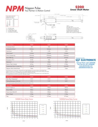
Npm s200 specsheet
1. Nippon Pulse
Your Partner in Motion Control NPM S200
Linear Shaft Motor
L = See Shaft Length
L1 = Usable Stroke + A
L2 = See Shaft Support Length
A = See Moving Coil Length
P = See Moving Coil Screw Pitch
Motor Cable
Length
Electrical Specs S200D S200T S200Q
Continuous Force1 18N 28N 38N
Continuous Current1 0.6Arms 0.6Arms 0.6Arms
Peak Force2 72N 112N 152N
Peak Current2 2.4Arms 2.4Arms 2.4Arms
Force Constant (Kf) 31N/Arms 47N/Arms 64N/Arms
Back EMF (Ke) 10V/m/s 16V/m/s 21V/m/s
Resistance 25°C,3 28.7Ω 43Ω 56Ω
Inductance3 19.3mH 29mH 39mH
Electric Time Constant 0.67ms 0.67ms 0.70ms
Fundemental Motor Constant (Km) 5.70N√W 7.24N√W 8.61N√W
Magnetic Pitch (North-North) 72mm 72mm 72mm
All specifications are for reference only. Specifications may change depending on servo driver selected. Consult Nippon Pulse.
1) Based on a temp rise of coil surface of 110°K over 25°C ambient temperature stalled forcer, and no external cooling or heat sinking
Addition of 25 cm x 25 cm x 2.5 cm aluminum heat sink increases continuous force by 20%
2) Can be maintained for a maximum of 40 seconds, higher forces and current possible for short periods of time, consult Nippon Pulse
3) All winding parameters listed are measured line-to-line (phase-to-phase)
Thermal Specs S200D S200T S200Q
Max Phase Temperature4 135°C 135°C 135°C
Thermal Resistance (Coil) (Kq) 11°C 7.3°C 5.6°C
4) The standard temperature difference between the coil and the forcer surface is 15°C
Forcer Specs S200D S200T S200Q
Forcer Length (A) 94mm 130mm 166mm
Forcer Width 40mm 40mm 40mm
Forcer Screw Pitch (P) 84mm 120mm 156mm
Forcer Weight 0.30kg 0.50kg 0.70kg
Force - Duty Curve
Gap S 200D
0.75mm 0.75mm 0.75mm
Force - Duty Curve
S 200Q
Sold & Serviced By:
S200D Force Duty Curve S200Q Force Duty Curve
Unless Otherwise Specified:
Dimensions are in mm
Tolerances are as follows:
Dimension (mm)
- 6
7 - 30
31 - 120
121 - 315
316 - 1000
1001 - 2000
2000 -
Serial Number
Gap
Bore
Label Mounting Surface
Total Length
Movable Range
Forcer Length
Forcer Screw Pitch
Support Length
Stroke Length
dep
Setting Pitch
Bending Radius
Reference End
Yellow Mark
Tolerance (mm)
±0.1
±0.2
±0.3
±0.5
±0.8
±1.2
±1.5
160
140
120
100
80
60
40
20
0
0 10 20 30 40 50 60 70 80 90 100
Force (N)
Duty(%)
2 0 °C
4 0 °C
6 0 °C
8 0 °C
1 1 0 °C
350
300
250
200
150
100
50
0
0 10 20 30 40 50 60 70 80 90 100
Force (N)
Duty(%)
2 0 °C
4 0 °C
6 0 °C
8 0 °C
1 1 0 °C
* Note 1
Cable length 300mm
The bending radius of the motor cable
should be 26.4 mm (wire diameter 4.4 * 6)
as suggested by the wire manufacturer.
This radius should be maintained. Use
supplied connector to attach the proper
high flex cable as required by your application.
ELECTROMATE
Toll Free Phone (877) SERVO98
Toll Free Fax (877) SERV099
www.electromate.com
sales@electromate.com
2. Shaft Length (mm) Shaft Mass (kg)
Stroke S200D S200T S200Q
100 244 280 316
150 294 330 366
200 344 380 416
250 394 430 466
300 444 480 516
350 524 560 596
400 574 610 646
450 624 660 696
500 674 710 746
550 724 760 796
600 774 810 846
650 824 860 896
700 874 910 946
750 964 1000 1036
800 1014 1050 1086
850 1064 1100 1136
900 1114 1150 1186
950 1164 1200 1236
1000 1214 1250 1286
1050 1264 1300 1336
1100 1314 1350 1386
1150 1364 1400 1436
1200 1414 1450 1486
1250 1464 1500 1536
1300 1514 1550 1586
1350 1564 1600 1636
1400 1614 1650 1686
1450 1664 1700 1736
1500 1714 1750 1786
1550 1764 1800 1836
1600 1814 1850 1886
1650 1864 1900 1936
1700 1914 1950 1986
1750 1964 2000 2036
1800 2014 2050 2086
1850 2064 2100 2136
1900 2114 2150 2186
1950 2164 2200 2236
2000 2214 2250 2286
Lead Wire
Wire Type UL 2464
Wire AWG 24
U Phase Orange
V Phase White
W Phase Gray
300mm lead wire bare leads
The bending radius of the motor ca-ble
should be 26.4mm as suggested
by the wire manufacturer.
CE Type Motor Cable
Support and Bending
S200
Linear Shaft Motor
Connector (Motor Cable)
Hall Effect Cable
Stroke Support Length Max. bending
0~300 25mm 0.00mm
301~700 40mm 0.30mm
701~1000 50mm 0.70mm
1001~max 50mm 0.90mm
Shaft Diameter (D) - 16mm ±0.1
Total Length (L)=Stroke (S)+Forcer Length (A)+(Support Length (L2)x2)
Forcer Spacing Distance
Forcer Spacing Distance
Stroke S200D S200T S200Q
100 0.5 0.6 0.6
150 0.6 0.7 0.7
200 0.7 0.8 0.9
250 0.8 0.9 1
300 0.9 1 1.1
350 1.1 1.1 1.2
400 1.2 1.2 1.3
450 1.3 1.4 1.4
500 1.4 1.5 1.5
550 1.5 1.6 1.6
600 1.6 1.7 1.8
650 1.7 1.8 1.9
700 1.8 1.9 2
750 2 2 2.1
800 2.1 2.2 2.2
850 2.2 2.3 2.3
900 2.3 2.4 2.5
950 2.4 2.5 2.6
1000 2.5 2.6 2.7
1050 2.6 2.7 2.8
1100 2.7 2.8 2.9
1150 2.8 2.9 3
1200 3 3 3.1
1250 3.1 3.1 3.2
1300 3.2 3.3 3.3
1350 3.3 3.4 3.4
1400 3.4 3.5 3.6
1450 3.5 3.6 3.7
1500 3.6 3.7 3.8
1550 3.7 3.8 3.9
1600 3.8 3.9 4
1650 3.8 4 4.1
1700 4.1 4.1 4.2
1750 4.2 4.2 4.3
1800 4.3 4.4 4.4
1850 4.4 4.5 4.5
1900 4.5 4.6 4.7
1950 4.6 4.7 4.8
2000 4.7 4.8 4.9
Sensor Cable Specs
Shaft Size (D) Forcer Size (A) Usable Stroke Options Options
S X XXXX XX XX
Receptacle Housing XMR-03V
Plug Housing XMP-03V
Retainer XMS-03V
Pin Contact SXM-001T-P0.6
Socket Contact SXA-001T-P0.6
To be installed by the user
Spec S200T S200Q
Forcer Spacing Distance 14mm 14mm
Pole (N/S) Distance 36mm 36mm
Forcer Length 130mm 166mm
Flip Forcers No Yes
— — — — —
D: Double (2) windings
T: Triple (3) windings
Q: Quadruple (4) windings
100-2000mm ST: Standard
WP: Waterproof
DA: Digital Hall Effect
CE: CE type motor
Blank: Standard
FO: Forcer Only
SO: Shaft Only
XX: Two digit for custom motor
Part Numbering System
Wire Type UL 1330
Wire AWG 24
U Phase Red
V Phase White
W Phase Black
Ground Wire UL 1330
Wire AWG 20
Frame Ground Green/Yellow
300mm lead wire bare leads
The bending radius of the motor cable
should be 16.96mm as suggested by the wire
manufacturer.
* Note 1
The bending radius of the motor cable should be R27.6mm (wire diameter 4.6 * 6) as suggested by the
wire manufacturer. This radius should be maintained. Use supplied connector to attach the proper
high flex cable as required by your application.
Wire Type UL 758
Wire AWG 28
VCC White/Red
GND White/Black
Sensor 1 Orange/Red
Sensor 2 Orange/Black
Sensor 3 Gray/Red
No Connec. Gray/Black
400mm lead wire bare leads
The bending radius of the motor ca-ble
should be 27.6mm as suggested
by the wire manufacturer.
Tandem Forcer
Hall Effect Specs
Wire Type UL 758
Wire AWG 28
VCC White/Red
GND White/Black
Sensor 1 Orange/Red
Sensor 2 Orange/Black
Sensor 3 Gray/Red
The bending radius of the sensor cable
should be R26.4mm (wire diameter 4.4
* 6) as suggested by the wire manufac-turer.
This radius should be maintained.
Attach the proper high flex cable as re-quired
by your application.
200
Stroke lengths available up to 2700mm. Contact Nippon Pulse for more
information.
Sold & Serviced By:
ELECTROMATE
Toll Free Phone (877) SERVO98
Toll Free Fax (877) SERV099
www.electromate.com
sales@electromate.com