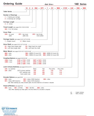
1. Ordering Guide - Belt Drive - 140 Series
120 Series Ordering
Table Series
Carriage Length
4 - 4 inches
Travel Length (see pages B-24, B-26 & B-28)
004 - 4 to 120 inches
Drive Shaft (see pages B-25, B-27 & B-29)
D1 - Right Hand single shaft
D3 - Right Hand thru shaft
D2
-
Motor Mount (see pages B-25, B-27, B-29 & B-42)
M00 - none M02 -
M99 - other
Coupling Options (see pages B-38 & B-39)
C000 - none
C999 - none
L00 - no switches
C130 to C134 - H100
C155 to C164 - H131
EOT & home switches
E00 - none
E01 - rotary (500 lines/rev)
E02 - rotary (1000 lines/rev)
E03 - rotary (1270 lines/rev)
- D1 - M02 - C155 - L04 - E00 - B00
M04 -
NEMA 34 mount (E)
M05 - NEMA 34 mount (M)
Prox (NPN)
E99 - other
B00 - none B01 - 24 VDC B02 - 90 VDC B99 - other
Sold & Serviced By:
Specifications subject to change without notice
NEMA 23 mount (E)
M03 - NEMA 23 mount (M)
Limit & Home Switches (see pages B-35 to B-37)
Encoder Options (see page B-45)
Power-off Brakes (see page B-44)
C407 to C413 - G100
C435 to C444 - G126
C470 to C480 - G158
L99 - other
note: When selecting any rotary encoder option, the Drive Shaft D3 or D4 above is required.
note: When selecting any brake option, the Drive Shaft D3 or D4 above is required.
(E) - English Interface
(M) - Metric Interface
Left Hand single shaft D4 -
Left Hand thru shaft
EOT switches only
home switch only
Reed Hall
L04
L07
L05
L08
L06
L09
L10
L11
L12
Prox (PNP)
L13
L14
L15
14 2 4 - CP1 - 1
Number of Bearings
1 - 1 bearing per carriage
2 - 2 bearings per carriage
004
Cover Plate
CP1 - top cover
plate only
CP0 - no cover
plate
Carriage Inserts (see pages B-25, B-27 & B-29)
1 - English mount 2 - Metric mount
C190 to C200 - H163
Guide
CP2 - top & side
cover plates
ELECTROMATE
Toll Free Phone (877) SERVO98
Toll Free Fax (877) SERV099
www.electromate.com
sales@electromate.com
2. Technical Reference - Belt Drive - 140 Series
( 90 kg)
( 30 kg)
( 180 kg)
( 22 N-m)
( 7 N-m)
( 38 N-m)
( 20 N-m)
( 7 N-m)
( 40 N-m)
( 45 kg)
( 4
34 lbs ( 15 kg) 34 lbs ( 15 kg)
Each Bearing Static Load Capacity 200 lbs ( 90 kg) 200 lbs ( 90 kg)
( 113 kg)
100 lbs ( 45 kg)
34 lbs ( 15 kg)
200 lbs ( 90 kg)
8 ft-lbs ( 11 N-m)
3 ft-lbs N-m)
14 ft-lbs ( 19 N-m)
4 ft-lbs ( 5,4 N-m)
1 ft-lbs ( 1,9 N-m)
8 ft-lbs ( 10 N-m)
100 lbs ( 45 kg)
200 lbs
68 lbs
400 lbs
16 ft-lbs
5 ft-lbs
28 ft-lbs
15 ft-lbs
5 ft-lbs
30 ft-lbs
100 lbs
250
Maximum Carriage Thrust Force 115 lbs ( 52 kg) 115 lbs ( 52 kg)
Maximum Speed 78 in/sec ( 2 m/sec ) 78 in/sec ( 2 m/sec )
dCenter to center distance (spacing) of each bearing on a single rail
- 2.088 in ( 53,0 mm)
2 dCenter distance of the bearing to top of carriage plate surface 1.375 in ( 34,9 mm) 1.375 in ( 34,9 mm)
r Table Material Base, Carriage, End Plates, & Cover Plate - 6061 anodized aluminum
Linear Rail Material Stainless Steel
Sold & Serviced By:
ELECTROMATE
Toll Free Phone (877) SERVO98
Toll Free Fax (877) SERV099
www.electromate.com
sales@electromate.com
Specifications subject to change without notice
Each Bearing Dyn. Capacity 2 m illion inches (50 km) of travel
Maximum Belt Tensile Force 250 lbs ( 113 kg)
Maximum Acceleration 193 in/sec2 ( 4,9 m/sec2)
For One (1) & Two (2) Bearing Carriages
Belt Properties Black, 16 mm wide, Polyurethane, Steel reinforced belt
Drive Pulley Weight 0.21 lbs 0,10 kg)
Drive Pulley Diameter 1.128 in 28,65 mm)
Drive Lead 3.543 in ( 90,00 mm)
Belt Stretch - x Load (lbs or N) 0.00025 in/ft per lbs 0,00476 mm/m per N)
Unidirectional Repeatability +/- 0.001 in
(+/- 0,0254 mm)
Bidirectional Repeatability
0.004 in 0,1016 mm)
Other
One (1) Bearing Carriage Two (2) Bearing Carriage
Specifications
Load Capacities
Dynamic Horizontal 2 million inches (50 km) of travel
Dynamic Horizontal 50 million inches (1270 km) of travel
Static Horizontal
Dynamic Roll Moment 2 million inches (50 km) of travel
Dynamic Roll Moment 50 million inches (1270 km) of travel
Static Roll Moment
Dyn. Pitch & Yaw Moment 2 million inches (50 km) of travel
Dyn. Pitch & Yaw Moment 50 million inches (1270 km) of travel
Static Pitch & Yaw Moment
(1)
Position Accuracy (Belt) < 0.010 in/ft (< 0,254 mm/300mm)
Friction Coefficient < 0.01
Motor Mount
Coupling
lbs
386 in/sec2 ( 9,8 m/sec2)
+/- (+/-
Footnotes:
NEMA 23 & 34 Mounts, Metric Mounts, and Gearheads
Two (2) different styles available
Each Bearing Dyn. Capacity 5 0 million inches (1270 km) of travel
(
(
(
Orthogonality (multi-axis systems) < 30 arc-seconds
Breakaway Torque < 40 oz-in (0,282 N-m)
(1) Position accuracy varies based on belt stretch. The given rating is based upon a carriage speed of 5 inches/sec (127 mm/sec) and a no load condition.
4. Technical Reference - Belt Drive - 140-CP0 Series
Optional Carriage Adapter Plate
Thru Shaft Option
Specifications subject to change without notice
Dimensions
Optional NEMA 23 Motor Mount Shown:
C
3.500
(88,90)
FOUR bearing carriage shown.
TWO bearing carriage will have
bearings centered on the carriage.
E # of spaces
C
(1)
A
B
This value is center to center distance (spacing) of the bearings on a single rail (d2).
This value is center distance of the bearing to top of carriage plate surface (dr(2) ).
Threaded Stainless Steel Inserts:
English Inserts (-1): (4) #8-32 x .25 inch deep TYP
Metric Inserts (-2): (4) M4 thd. x 8 mm deep TYP
4.000
(101,60)
.193 (4,90) Dia.Thru Holes M # of Holes
C' Bored Opposite Side .312
(7,92) Dia. x .190 (4,83) Deep
2.500
(63,50)
4.545
(115,43)
2.500
(63,50)
1.375
(34,92)
2.088
(53,03)
.156 TYP
(3,96) TYP
inches
(mm)
0.250 TYP
(6,35) TYP
.187 TYP
(4,75) TYP
1.875
(47,63)
1.875
(47,63)
.375
(9,52)
o
3.125
(79,37)
(1)
.250 TYP
(6,35) TYP
(see page B-34)
(2)
1.058
(26,87)
.375 (9,53)
304 Woodruff
Keyway
2.875
(73,03)
.375
(9.52)
1.875
(47,63)
(4) Holes on 2.625 (66,68) Bolt Circle Dia.
English Mount (M02): #10-24 thd.
Metric Mount (M03): M5 thd.
Single Screw Belt
Tension Adjustment
Rubber Bumpers
(both ends)
1.502 (38,15)
Pilot Dia. TYP
- Without Cover Plates -
Right Hand Single Shaft
Configuration Shown (D1 option)
For optional coupling info see
pages B-38 & B-39. Also, coupling
cover included on top of optional
motor mounts.
D3 & D4 (D3 shown)
.375
(9,52)
o
.313 (7,95)
303 Woodruff
Keyway .625
(15,88)
1.375
(34,93)
1.875
(47,62)
.250
(6,35)
3.000
(76,20)
1.128
(28,65)
1.456
(36,98)
.193 (4,90) Dia. Thru Holes
2.188
(55,57)
1.875
(47,63)
1.875
(47,63)
Note: Any 130 or 140 series table can be mounted on top of a second 130 or 140 series table, in order to create X-Y multiple axis configurations. LINTECH recom-mends
that a 2 bearing carriage be used for the bottom axis, and that the top axis should never extend out more than 18 inches in either direction, from the bottom axis
carriage edge, without the use of a support bearing system on the outer edges of the top axis. The 130-CP1, 130-CP2 or 140 series requires a Carriage Adapter Plate
option. The carriage's threaded stainless steel insert hole pattern exactly matches the base mounting hole pattern on each table, therefore no adapter bracket or extra
machining is required. However a precision square tool, or micrometer depth gauge, is required in order to obtain an orthogonality between the two tables of < 30 arc-seconds.
The table base, carriage top & carriage sides are all precision machined. LINTECH's 100 or 120 series tables should be used for the bottom axis in a mutiple
axes application for better system rigidity, performance, and life.
5. Technical Reference - Belt Drive - 140-CP1 Series
Dimensions & Specifications
Travel
Length
Table Dimensions
Model
Number lbs
1.188
(30,2) 3 8 4
(100)
14x4006-CP1 1.5
1.438
(36,5) 23 48 42
(1060)
0.688
(17,5) 27 56 48
(1215)
1.813
(46,1) 29 60 54
(1370)
1.063
(27,0) 33 68 60
(1520)
Sold & Serviced By:
Specifications subject to change without notice
- With Top Cover Plate Only -
14x4004-CP1
Belt
Weight
ounces
(gm)
1.3
(36,8)
0.313
(8,0) 5 12 6
(150)
1.313
(33,4) 5 12 8
(200)
1.438
(36,5) 7 16 12
(300)
1.563
(39,7) 9 20 16
(405)
1.688
(42,9) 11 24 20
(505)
1.813
(46,1) 13 28 24
(605)
1.063
(27,0) 17 36 30
(760)
0.313
(8,0) 21 44 36
(910)
x = 1; Carriage has 1 bearing; Carriage weight = 1.4 lbs. (0,64 kg)
x = 2; Carriage has 2 bearings; Carriage weight = 1.5 lbs. (0,68 kg)
(42,5)
14x4008-CP1 1.7
(48,2)
14x4012-CP1 2.1
(59,5)
14x4016-CP1 2.5
(70,9)
14x4020-CP1 2.9
(82,2)
14x4024-CP1 3.3
(93,6)
14x4030-CP1 3.9
(110,6)
14x4036-CP1 4.5
(127,6)
14x4042-CP1 5.1
(144,6)
14x4048-CP1 5.7
(161,6)
14x4054-CP1 6.3
(178,6)
14x4060-CP1 6.9
(195,6)
(kg)
inches
(mm)
C
inches
(mm)
Mounting Dimensions
4.8
(2,2)
inches
(mm)
A
B E M
Table
Weight
(1)
5.3
(2,4)
8.0
(203,2)
14.0
(355,6)
5.8
(2,6)
10.0
(254,0)
16.0
(406,4)
6.3
(2,9)
12.0
(304,8)
18.0
(457,2)
7.3
(3,3)
16.0
(406,4)
22.0
(558,8)
8.3
(3,8)
20.0
(508,0)
26.0
(660,4)
9.3
(4,2)
24.0
(609,6)
30.0
(762,0)
10.3
(4,7)
28.0
(711.2)
34.0
(863,6)
11.8
(5,4)
34.0
(863,6)
40.0
(1016,0)
13.3
(6,0)
40.0
(1016,0)
46.0
(1168,4)
14.8
(6,7)
46.0
(1168,4)
52.0
(1320,8)
16.3
(7,4)
52.0
(1320,8)
58.0
(1473,2)
17.8
(8,1)
58.0
(1473,2)
64.0
(1625,6)
64.0
(1625,6)
70.0
(1778,0)
Footnotes:
(1) Weight shown is with a 1 bearing carriage [1.4 lbs (0,64 kg)], a NEMA 23 motor mount [0.34 lbs (0,16 kg)], and a H100 style [0.08 lbs (0,04 kg)] coupling.
When using a 2 bearing carriage add 0.1 lbs (0,04 kg) to each value.
ELECTROMATE
Toll Free Phone (877) SERVO98
Toll Free Fax (877) SERV099
www.electromate.com
sales@electromate.com
6. Technical Reference - Belt Drive - 140-CP1 Series
Right Hand Single Shaft
Configuration Shown (D1 option)
Optional Carriage Adapter Plate
Thru Shaft Option
Specifications subject to change without notice
Dimensions
- With Top Cover Plate Only -
inches
(mm)
1.875
(47,63)
FOUR bearing carriage shown.
TWO bearing carriage will have
bearings centered on the carriage.
(1)
A
B
1.875
(47,63)
1.875
(47,63)
.193 (4,90) Dia. Thru Holes
1.875
(47,63)
1.875
(47,63)
.193 (4,90) Dia.Thru Holes M # of Holes
C' Bored Opposite Side .312
(7,92) Dia. x .190 (4,83) Deep
.156 TYP
(3,96) TYP
2.188
(55,57)
This value is center to center distance (spacing) of the bearings on a single rail (d2).
(1)
Optional NEMA 23 Motor Mount Shown:
Note: Any 130 or 140 series table can be mounted on top of a second 130 or 140 series table, in order to create X-Y multiple axis configurations. LINTECH recom-mends
that a 2 bearing carriage be used for the bottom axis, and that the top axis should never extend out more than 18 inches in either direction, from the bottom axis
carriage edge, without the use of a support bearing system on the outer edges of the top axis. The 130-CP1, 130-CP2 or 140 series requires a Carriage Adapter Plate
option. The carriage's threaded stainless steel insert hole pattern exactly matches the base mounting hole pattern on each table, therefore no adapter bracket or extra
machining is required. However a precision square tool, or micrometer depth gauge, is required in order to obtain an orthogonality between the two tables of < 30 arc-seconds.
The table base, carriage top & carriage sides are all precision machined. LINTECH's 100 or 120 series tables should be used for the bottom axis in a mutiple
axes application for better system rigidity, performance, and life.
D3 & D4 (D3 shown)
.375
(9,52)
o
.313 (7,95)
303 Woodruff
Keyway .625
(15,88)
1.375
(34,93)
1.875
(47,62)
C
E # of spaces
C
This value is center distance of the bearing to top of carriage plate surface (dr(2) ).
Threaded Stainless Steel Inserts:
English Inserts (-1): (4) #8-32 x .25 inch deep TYP
Metric Inserts (-2): (4) M4 thd. x 8 mm deep TYP
4.000
(101,60)
3.500
(88,90)
2.500
(63,50)
4.545
(115,43)
2.500
(63,50)
1.375
(34,92)
2.088
(53,03)
0.250 TYP
(6,35) TYP
.187 TYP
(4,75) TYP
.375
(9,52)
o
3.125
(79,37) .250 TYP
(6,35) TYP
(see page B-34)
(2)
1.058
(26,87)
.375 (9,53)
304 Woodruff
Keyway
2.875
(73,03)
.375
(9.52)
(4) Holes on 2.625 (66,68) Bolt Circle Dia.
English Mount (M02): #10-24 thd.
Metric Mount (M03): M5 thd.
Single Screw Belt
Tension Adjustment
Rubber Bumpers
(both ends)
1.502 (38,15)
Pilot Dia. TYP
For optional coupling info see
pages B-38 & B-39. Also, coupling
cover included on top of optional
motor mounts.
.250
(6,35)
3.000
(76,20)
1.128
(28,65)
1.456
(36,98)
7. Technical Reference - Belt Drive - 140-CP2 Series
Dimensions & Specifications - With Top Cover Plate Only -
Travel
Length
Table Dimensions
Model
Number lbs
14x4004-CP2
1.188
(30,2) 3 8 4
(100)
14x4006-CP2 1.5
1.438
(36,5) 23 48 42
(1060)
0.688
(17,5) 27 56 48
(1215)
1.813
(46,1) 29 60 54
(1370)
1.063
(27,0) 33 68 60
(1520)
Sold & Serviced By:
Specifications subject to change without notice
Belt
Weight
ounces
(gm)
1.3
(36,8)
0.313
(8,0) 5 12 6
(150)
1.313
(33,4) 5 12 8
(200)
1.438
(36,5) 7 16 12
(300)
1.563
(39,7) 9 20 16
(405)
1.688
(42,9) 11 24 20
(505)
1.813
(46,1) 13 28 24
(605)
1.063
(27,0) 17 36 30
(760)
0.313
(8,0) 21 44 36
(910)
x = 1; Carriage has 1 bearing; Carriage weight = 1.4 lbs. (0,64 kg)
x = 2; Carriage has 2 bearings; Carriage weight = 1.5 lbs. (0,68 kg)
(42,5)
14x4008-CP2 1.7
(48,2)
14x4012-CP2 2.1
(59,5)
14x4016-CP2 2.5
(70,9)
14x4020-CP2 2.9
(82,2)
14x4024-CP2 3.3
(93,6)
14x4030-CP2 3.9
(110,6)
14x4036-CP2 4.5
(127,6)
14x4042-CP2 5.1
(144,6)
14x4048-CP2 5.7
(161,6)
14x4054-CP2 6.3
(178,6)
14x4060-CP2 6.9
(195,6)
(kg)
inches
(mm)
C
inches
(mm)
Mounting Dimensions
5.0
(2,3)
inches
(mm)
A
B E M
Table
Weight
(1)
5.5
(2,5)
8.0
(203,2)
14.0
(355,6)
6.0
(2,7)
10.0
(254,0)
16.0
(406,4)
6.6
(3,0)
12.0
(304,8)
18.0
(457,2)
7.7
(3,5)
16.0
(406,4)
22.0
(558,8)
8.7
(3,9)
20.0
(508,0)
26.0
(660,4)
9.8
(4,5)
24.0
(609,6)
30.0
(762,0)
10.9
(5,0)
28.0
(711.2)
34.0
(863,6)
12.5
(5,7)
34.0
(863,6)
40.0
(1016,0)
14.0
(6,4)
40.0
(1016,0)
46.0
(1168,4)
15.6
(7,1)
46.0
(1168,4)
52.0
(1320,8)
17.2
(7,8)
52.0
(1320,8)
58.0
(1473,2)
18.8
(8,5)
58.0
(1473,2)
64.0
(1625,6)
64.0
(1625,6)
70.0
(1778,0)
Footnotes:
(1) Weight shown is with a 1 bearing carriage [1.4 lbs (0,64 kg)], a NEMA 23 motor mount [0.34 lbs (0,16 kg)], and a H100 style [0.08 lbs (0,04 kg)] coupling.
When using a 2 bearing carriage add 0.1 lbs (0,04 kg) to each value.
ELECTROMATE
Toll Free Phone (877) SERVO98
Toll Free Fax (877) SERV099
www.electromate.com
sales@electromate.com
8. Technical Reference - Belt Drive - 140-CP2 Series
Thru Shaft Option
Specifications subject to change without notice
Dimensions - With Top Cover Plate Only -
inches
(mm)
3.225
(81,92)
FOUR bearing carriage shown.
TWO bearing carriage will have
bearings centered on the carriage.
This value is center to center distance (spacing) of the bearings on a single rail (d2(1) ).
This value is center distance of the bearing to top of carriage plate surface (dr(2) ).
Optional NEMA 23 Motor Mount Shown:
1.456
(36,98)
Note: Any 130 or 140 series table can be mounted on top of a second 130 or 140 series table, in order to create X-Y multiple axis configurations. LINTECH recom-mends
that a 2 bearing carriage be used for the bottom axis, and that the top axis should never extend out more than 18 inches in either direction, from the bottom axis
carriage edge, without the use of a support bearing system on the outer edges of the top axis. The 130-CP1, 130-CP2 or 140 series requires a Carriage Adapter Plate
option. The carriage's threaded stainless steel insert hole pattern exactly matches the base mounting hole pattern on each table, therefore no adapter bracket or extra
machining is required. However a precision square tool, or micrometer depth gauge, is required in order to obtain an orthogonality between the two tables of < 30 arc-seconds.
The table base, carriage top & carriage sides are all precision machined. LINTECH's 100 or 120 series tables should be used for the bottom axis in a mutiple
axes application for better system rigidity, performance, and life.
D3 & D4 (D3 shown)
.375
(9,52)
o
.313 (7,95)
303 Woodruff
Keyway .625
(15,88)
1.375
(34,93)
1.875
(47,62)
C
E # of spaces
C
.193 (4,90) Dia.Thru Holes M # of Holes
C' Bored Opposite Side .312
(7,92) Dia. x .190 (4,83) Deep
.156 TYP
(3,96) TYP
1.875
(47,63)
1.875
(47,63)
1.875
(47,63)
.193 (4,90) Dia. Thru Holes
2.188
(55,57)
1.875
(47,63)
1.875
(47,63)
(1)
A
B
2.500
(63,50)
1.375
(34,92)
2.088
(53,03)
3.125
(79,37)
(2)
.375
(9.52)
(4) Holes on 2.625 (66,68) Bolt Circle Dia.
English Mount (M02): #10-24 thd.
Metric Mount (M03): M5 thd.
Single Screw Belt
Tension Adjustment
Rubber Bumpers
(both ends)
1.502 (38,15)
Pilot Dia. TYP
Optional Carriage Adapter Plate
(see page B-34)
2.875
(73,03)
.250
(6,35)
3.000
(76,20)
Threaded Stainless Steel Inserts:
English Inserts (-1): (4) #8-32 x .25 inch deep TYP
Metric Inserts (-2): (4) M4 thd. x 8 mm deep TYP
4.000
(101,60)
3.500
(88,90)
2.500
(63,50)
4.545
(115,43)
0.250 TYP
(6,35) TYP
.187 TYP
(4,75) TYP
.375
(9,52)
o
1.058
(26,87)
.375 (9,53)
304 Woodruff
Keyway
Right Hand Single Shaft
Configuration Shown (D1 option)
For optional coupling info see
pages B-38 & B-39. Also, coupling
cover included on top of optional
motor mounts.
1.128
(28,65)