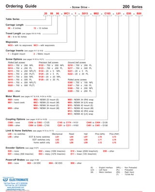
1. Ordering Guide - Screw Drive - 200 Series
Table Series
6 inches
Travel Length (see pages H-6 & H-8)
06 - 6 to 55 inches
Waycovers
WC0 - with no waycovers
Screw Options (see pages H-18 to H-21)
Rolled ball screws
S013 -
S014 -
.750 x .200 NPL
.750 x .200 PL
other
S122
S123
S124
Coupling Options (see pages H-22 to H-23)
C000 - none
C056 to C063 - C125
C084 to C090 - C150
Limit & Home Switches (see pages H-15 to H-17)
EOT & home switches
Encoder Options (see page H-27)
E00 - none
E01 - rotary (500 lines/rev)
Power-off Brakes (see page H-26)
Sold & Serviced By:
Specifications subject to change without notice
06 - WC1 - 1 - - M02 - C165 - L01 - E00 - B00
Ground ball screws
S217 - .750 x .500 PL
Rolled acme screws
S307 -
M08 - NEMA 34 (RH) wrap
M09 -
C165 to C174 - H131
C201 to C211 - H163
E02 - rotary (1000 lines/rev)
E03 - rotary (1270 lines/rev)
Prox (NPN)
Prox (PNP)
E10 - linear (2500 lines/inch) E99 - other
B00 - none B03 - 24 VDC B04 - 90 VDC B99 - other
C445 to C454 - G126
C999 - other C481 to C491 - G158
EOT switches only
L00 - no switches
home switch only
Mechanical Reed Hall
L01
L02
L03
L04
L05
L06
L07
L08
L09
L10
L11
L12
L99 - other
E11 - linear (125 lines/mm)
1 - English mount 2 - Metric mount
S015 - .750 x .200 NPL(T)
- .750 x .200 PL
-
-
20 x 5 PL
20 x 20 PL
.750 x .100 NPL
.750 x .100 PL
.750 x .200 NPL
.750 x .200 PL
Motor Mount (see pages H-7 & H-9, H-24 to H-25)
M00 - none
M01 - hand crank
M02 - NEMA 23 mount (E)
M04 - NEMA 34 mount (E)
M13 -
NEMA 42 (LH) wrap
M99 -
NEMA 34 (LH) wrap
M12 - NEMA 42 (RH) wrap
M03 - NEMA 23 mount (M)
M05 - NEMA 34 mount (M)
S999 - other
(E) - English Interface
(LH) - Left Hand
(M) - Metric Interface
(NPL) - Non Preloaded
(PL) - Preloaded
(RH) - Right Hand
(T) - Turcite Nut
S216
S221
S222
-
-
-
S306
S308
S309
S013
L13
L14
L15
06
06 - 12 - 12 inches
WC1 - with waycovers
S017 -
S018 -
.750 x .500 NPL
.750 x .500 PL
S019 - .750 x .500 NPL(T)
Precision ball screws
- .750 x .200 NPL
-
.750 x .200 PL
-
20 x 5 NPL
-
20 x 5 PL
-
20 x 20 NPL
-
20 x 20 PL
S125
S128
S129
Carriage Length
Carriage Inserts (see pages H-7 & H-9)
20
M10 - NEMA 42 mount (E)
M11 - NEMA 42 mount (M)
S016 - .750 x .200 PL(T)
S020 - .750 x .500 PL(T)
ELECTROMATE
Toll Free Phone (877) SERVO98
Toll Free Fax (877) SERV099
www.electromate.com
sales@electromate.com
2. Technical Reference - Screw Drive - 200 Series
Load Capacities 6 inch (2 bearing) Carriage 12 inch (4 bearing) Carriage
8,800 lbs
3,000 lbs
15,200 lbs
1,580 ft-lbs
540 ft-lbs
2,730 ft-lbs
2,485 ft-lbs
845 ft-lbs
4,300 ft-lbs
2,200 lbs
750 lbs ( 340 kg) 750 lbs ( 340 kg)
lbs
1,050 lbs
( 3992
270 ( 366
( 1360
( 6895
270 lbs ( 122 kg) 270 lbs ( 122 kg)
772 in/sec2
kg)
kg)
kg)
N-m)
N-m)
( 3701 N-m)
( 3369 N-m)
( 1146 N-m)
( 5830 N-m)
( 998 kg)
( 1724 kg)
( 476 kg)
( 19,6 m/sec2)
d1 Center to center distance (spread) between the two rails 5.280 in (134,1 mm) 5.280 in (134,1 mm)
Table Material Base, Carriage, End Plates, & Cover Plate option - 6061 anodized aluminum
Linear Rail Material
Case Hardened Steel
Acme Screw - Stainless Steel
Rolled Ball, Precision Ball, & Ground Ball - Case Hardened Steel
(<
(<
1,02
1,02
microns/25mm)
microns/25mm)
Screw Material (see pages H-18 to H-21)
Orthogonality (multi-axis systems) < 15 arc-seconds
Friction Coefficient < 0.01
Motor Mount NEMA 23 & 34 Mounts, Metric Mounts, Motor Wraps, and Hand Crank Option
Coupling Three (3) different styles available
Specifications subject to change without notice
Specifications
Dynamic Horizontal 2 million inches (50 km) of travel
Dynamic Horizontal 50 million inches (1270 km) of travel
Static Horizontal
Dynamic Roll Moment 2 million inches (50 km) of travel
Dynamic Roll Moment 50 million inches (1270 km) of travel
Static Roll Moment
Dyn. Pitch & Yaw Moment 2 million inches (50 km) of travel
Dyn. Pitch & Yaw Moment 50 million inches (1270 km) of travel
Static Pitch & Yaw Moment
Each Bearing Dyn. Capacity 2 m illion inches (50 km) of travel
Each Bearing Dyn. Capacity 5 0 million inches (1270 km) of travel
Each Bearing Static Load Capacity
Thrust Force Capacity 10 million screw revolutions
Thrust Force Capacity 500 million screw revolutions
Maximum Acceleration
d2 Center to center distance (spacing) of the bearings on a single rail
dr Center distance of the bearing to top of carriage plate surface
4,400 lbs ( 1996 kg)
1,500 lbs kg)
7,600 lbs kg)
790 ft-lbs ( 1071 N-m)
ft-lbs N-m)
1,365 ft-lbs N-m)
175 ft-lbs ( 237 N-m)
58 ft-lbs ( 79 N-m)
300 ft-lbs ( 407 N-m)
2,200 lbs ( 998 kg)
3,800 lbs ( 1724 kg)
1,050 lbs ( 476 kg)
386 in/sec2
( 9,8 m/sec2)
1.900 in ( 48,3 mm)
( 680
( 3447
( 1851
( 2142
1.900 in ( 48,3 mm)
( 732
3,800
- 7.870 in (199,9 mm)
For 6 inch (2 bearing) & 12 inch (4 bearing) Carriages
Other
Screw Material (see pages H-18 to H-21)
Straightness < 0.00004 in/in
Flatness < 0.00004 in/in
Waycover Material Hypilon Polyester Bellows firmly mounted to carriage & end plates
Sold & Serviced By:
ELECTROMATE
Toll Free Phone (877) SERVO98
Toll Free Fax (877) SERV099
www.electromate.com
sales@electromate.com
4. Technical Reference - Screw Drive - 200-WC0 Series
Optional NEMA 23 Motor Mount Shown:
(4) Holes on 2.625 (66,68) Bolt Circle Dia.
English Mount (M02): #10-24 thd.
Metric Mount (M03): M5 thd.
1.502 (38,15) Pilot Dia. TYP
Specifications subject to change without notice
Dimensions - Without Waycovers -
12 inch (304,8 mm) FOUR bearing carriage shown.
6 inch (152,4 mm) TWO bearing carriage will have
bearings centered on the carriage.
(2)
7.870
(199,90)
A
B
inches
(mm)
.625
(15,87)
.625
(15,87)
.375
(9,53)
4 Holes; 6 inch (152,4 mm) carriage
(1) This value is center to center distance (spread) between the two rails (d1).
6 Holes; 12 inch (304,8 mm) carriage
(2) This value is center to center distance (spacing) of the bearings on a single rail (d2).
(3) This value is center distance of the bearing to top of carriage plate surface (dr).
Note: M # of Holes
o
3.750
(95,25)
Any 200 series table can be mounted on top of any second 200 series, in order to create X-Y multiple axis configurations. The carriage's threaded stainless steel
insert hole pattern DOES NOT exactly match the base mounting hole pattern on each table, therefore machining of the bottom axis carriage plate is required.
Contact LINTECH.
2.875
(73,02)
6.000
(152,4)
4.375
(111,12)
1.750
(44,45)
o
2.500
(63,50)
4.750
(120,65)
5.375
(136,52)
5.280
(134,11)
7.500
(190,50) 8.500
(215,90)
0.625 TYP
(15,87) TYP
1.000
(25,40)
.500
(12,70)
.375 (9,53)
404 Woodruff Keyway
(1)
0.500
(12,70)
.625
(15,87)
(3)
EOT & HOME
Switch Cable Egress
.343 (8,71) Dia.Thru Holes,
C'Bored Opposite Side
.500 (12,70) Dia. x .340 (8,64) Deep
1.900
(48,26)
1.250 TYP
(31,75) TYP
Threaded Stainless Steel Inserts:
English Inserts (-1): 5/16 -24 x .75 inch deep TYP
Metric Inserts (-2): M8 thd. x 19 mm deep TYP
C
D # of spaces
C 3.500
(88,90)
3.500
(88,90)
3.500
(88,90)
Bearing Lube Fittings
0.375
(9,53)
For optional coupling info
see pages H-22 & H-23.
Also, coupling cover in-cluded
on top of optional
motor mounts.
Sold & Serviced By:
ELECTROMATE
Toll Free Phone (877) SERVO98
Toll Free Fax (877) SERV099
www.electromate.com
sales@electromate.com
6. Technical Reference - Screw Drive - 200-WC1 Series
0.625 TYP
(15,87) TYP
4 Holes; 6 inch (152,4 mm) carriage
6 Holes; 12 inch (304,8 mm) carriage
Threaded Stainless Steel Inserts:
English Inserts (-1): 5/16 -24 x .75 inch deep TYP
Metric Inserts (-2): M8 thd. x 19 mm deep TYP
o
.500
(12,70)
(1)
7.500
(190,50) 8.500
(215,90)
For optional coupling info
see pages H-22 & H-23.
Also, coupling cover in-cluded
on top of optional
motor mounts.
Optional NEMA 23 Motor Mount Shown:
(4) Holes on 2.625 (66,68) Bolt Circle Dia.
English Mount (M02): #10-24 thd.
Metric Mount (M03): M5 thd.
1.502 (38,15) Pilot Dia. TYP
2.875
(73,02)
1.750
(44,45)
Specifications subject to change without notice
Dimensions - With Waycovers -
4.750
(120,65)
0.375
(9,53)
12 inch (304,8 mm) FOUR bearing carriage shown.
6 inch (152,4 mm) TWO bearing carriage will have
bearings centered on the carriage.
(2)
7.870
(199,90)
A
B
inches
(mm)
5.280
(134,11)
0.500
(12,70)
.625
(15,87)
.625
(15,87)
.375
(9,53)
o
1.250 TYP
(31,75) TYP
6.000
(152,4)
4.375
(111,12)
5.375
(136,52)
(3)
3.500
(88,90)
D # of spaces
C 3.500
(88,90)
3.500
(88,90)
.343 (8,71) Dia.Thru Holes,
C'Bored Opposite Side
.500 (12,70) Dia. x .340 (8,64) Deep
1.900
(48,26)
(1) This value is center to center distance (spread) between the two rails (d1).
1.000
(25,40)
Bearing Lube Fittings
(2) This value is center to center distance (spacing) of the bearings on a single rail (d2).
(3) This value is center distance of the bearing to top of carriage plate surface (dr).
.375 (9,53)
404 Woodruff Keyway
EOT & HOME
Switch Cable Egress
.625
(15,87)
C
M # of Holes
3.750
(95,25)
2.500
(63,50)
Note: Any 200 series table can be mounted on top of any second 200 series, in order to create X-Y multiple axis configurations. The carriage's threaded stainless steel
insert hole pattern DOES NOT exactly match the base mounting hole pattern on each table, therefore machining of the bottom axis carriage plate is required.
Contact LINTECH.
Sold & Serviced By:
ELECTROMATE
Toll Free Phone (877) SERVO98
Toll Free Fax (877) SERV099
www.electromate.com
sales@electromate.com