Downloaded 428 times


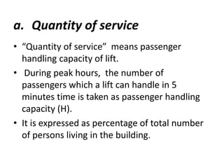


The document discusses lifts, including their components, types, space requirements, and design considerations. Lifts are installed in multi-storey buildings to avoid fatigue from using stairs and allow for quick vertical circulation. A lift shaft extends from below the ground floor to house equipment and buffers, and a machine room located at the top of the shaft houses additional equipment. Design considerations for lifts include quantity of service, expressed as passenger handling capacity, and quality of service, expressed as waiting time.


