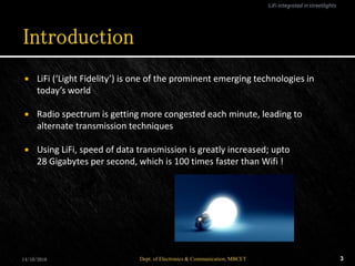
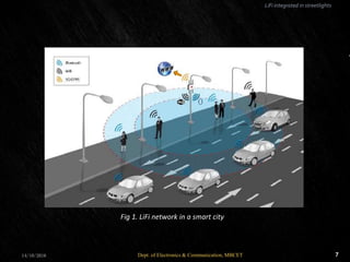
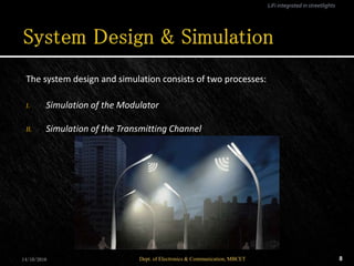
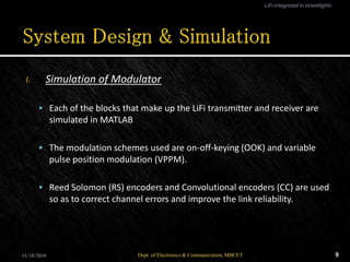
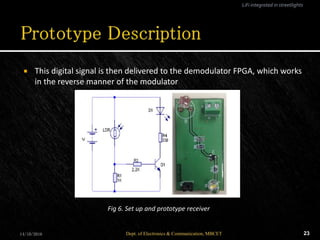
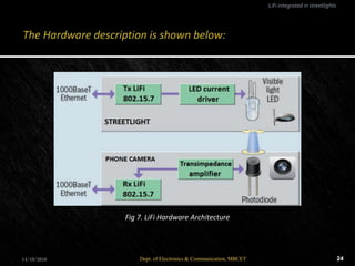
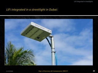
Presented by
Nikhil K. Kuriakose
MBCET,
Trivandrum.
 Introduction
 LiFi in Streetlights
 System Design & Simulation
 Prototype Description
 Advantages & Applications
 Conclusion
 References
14/10/2016 Dept. of Electronics & Communication, MBCET 2
LiFi integrated in streetlights
 LiFi (‘Light Fidelity’) is one of the prominent emerging technologies in
today’s world
 Radio spectrum is getting more congested each minute, leading to
alternate transmission techniques
 Using LiFi, speed of data transmission is greatly increased; upto
28 Gigabytes per second, which is 100 times faster than Wifi !
14/10/2016 3Dept. of Electronics & Communication, MBCET
LiFi integrated in streetlights
 Light based WiFi
 Light is used instead of radio waves to transmit information
 Transmitter fitted with LED lamps act like WiFi modems
 Provides illumination as well as data communication
14/10/2016 4Dept. of Electronics & Communication, MBCET
LiFi integrated in streetlights
 Capacity
Spectrum is 10,000 times greater than that of radio frequency
 Efficiency
Highly efficient since LED consumes less energy
 Availability
Light waves available everywhere
 Security
Cannot penetrate through walls, hence data cannot be intercepted
14/10/2016 5Dept. of Electronics & Communication, MBCET
LiFi integrated in streetlights
 Formed by streetlight as transmitter and mobile phone camera as
receiver.
 Streetlights receive data via PLC & modulate the information through LED
bulb
 The light is received by the smartphone through a photodiode integrated
in it’s camera
 Uplink is via Bluetooth, ZigBee or WiFi
14/10/2016 6Dept. of Electronics & Communication, MBCET
LiFi integrated in streetlights
714/10/2016 Dept. of Electronics & Communication, MBCET
LiFi integrated in streetlights
Fig 1. LiFi network in a smart city
The system design and simulation consists of two processes:
I. Simulation of the Modulator
II. Simulation of the Transmitting Channel
14/10/2016 8Dept. of Electronics & Communication, MBCET
LiFi integrated in streetlights
I. Simulation of Modulator
 Each of the blocks that make up the LiFi transmitter and receiver are
simulated in MATLAB
 The modulation schemes used are on-off-keying (OOK) and variable
pulse position modulation (VPPM).
 Reed Solomon (RS) encoders and Convolutional encoders (CC) are used
so as to correct channel errors and improve the link reliability.
14/10/2016 9Dept. of Electronics & Communication, MBCET
LiFi integrated in streetlights
 An interleaver is included to avoid burst errors
 RLL (Run Length Limited) encoders are used to balance the DC level of
the output
 The RLL encoders used here are Manchester and 4B6B encoders
14/10/2016 10Dept. of Electronics & Communication, MBCET
LiFi integrated in streetlights
14/10/2016 11Dept. of Electronics & Communication, MBCET
LiFi integrated in streetlights
Fig 2. Block diagram of Modulator
 The bit error rate (BER) is plotted after addition of AWGN (Additive White
Gaussian Noise).
 It is observed that the operating mode that has the lowest data rate
presents the best performance because of the high protection.
 SNR = 10 dB is chosen to illustrate the effect on an image transmission
using our simulated LiFi system.
 Also, if a SNR = 15 dB is chosen, a level of BER and image quality are
acceptable for all modes of operation.
14/10/2016 Dept. of Electronics & Communication, MBCET 12
LiFi integrated in streetlights
14/10/2016 13Dept. of Electronics & Communication, MBCET
LiFi integrated in streetlights
Fig 3. Performance plot (BER vs. SNR)
14/10/2016 14Dept. of Electronics & Communication, MBCET
LiFi integrated in streetlights
Fig 4. The quality of the image clearly shows the effect of coding
II. Simulation of Transmitting Channel
 The transmitting medium (in this case, air), is an essential factor that
affects the LiFi reception
 Some of the factors that affect reception include ambient light, Line Of
Sight (LOS), Field Of View (FOV), height of the streetlight, etc
 Analysis is carried out by taking the impulse response of the channel,
which is then used to analyze and combat the effects of channel
distortions
14/10/2016 15Dept. of Electronics & Communication, MBCET
LiFi integrated in streetlights
 For analysis, the link is considered to have LOS between the streetlight
and mobile phone
 There may be scattering effects due to reflections from objects. These
reflections are considered in the simulation process
 The channel response is given by
h(t; S, R) = h(k) (t; S, R)
where
S, R  position of transmitter and receiver respectively
k  reflection order
14/10/2016 16Dept. of Electronics & Communication, MBCET
LiFi integrated in streetlights
 To calculate the kth reflection, we use the formula:
h (k) (t; S, R) = h (0) (t; S, {r, n, π/ 2, dr 2 }) ⊗ h k−1 (t; {r, n, 1}, R)
where
h (0)  channel response for zeroth order reflection
n  mode number, which specifies directionality of the source
14/10/2016 17Dept. of Electronics & Communication, MBCET
LiFi integrated in streetlights
14/10/2016 18Dept. of Electronics & Communication, MBCET
LiFi integrated in streetlights
Fig 5. Channel response h(t; S, R)
 From the graph, it is observed that the reflections do not create any
problems for detection because the direct beam is much stronger than
others
 The predominance of LOS beam between transmitter and receiver is
clearly observed
14/10/2016 19Dept. of Electronics & Communication, MBCET
LiFi integrated in streetlights
I. Transmitter
 Transmitter and receiver have been implemented on two separate
FPGAs
 The transmitter front-end, (the streetlight), is comprised of a Spartan
3E-xc3s500E FPGA, acting as the LiFi modulator
 It also includes the LED driver circuit and a commercial high power
white LED as the light emitting source
14/10/2016 20Dept. of Electronics & Communication, MBCET
LiFi integrated in streetlights
 The data stream received from PLC is delivered via an Ethernet port to the
FPGA and encoded
 Then the modulated signal is fed to the LED driver circuit, which acts in
switching mode, varying the current of the streetlight LED
14/10/2016 21Dept. of Electronics & Communication, MBCET
LiFi integrated in streetlights
II. Receiver
 The FPGA used in the receiver has a larger memory, in order to store
the performance measurements
 The receiver front-end, at the phone’s camera, is equipped with a
Spartan 6-xc6slx16 FPGA
 An external circuit has been designed and implemented to capture the
signal using an LDR (light-dependent resistor)
14/10/2016 22Dept. of Electronics & Communication, MBCET
LiFi integrated in streetlights
 This digital signal is then delivered to the demodulator FPGA, which works
in the reverse manner of the modulator
14/10/2016 23Dept. of Electronics & Communication, MBCET
LiFi integrated in streetlights
Fig 6. Set up and prototype receiver
14/10/2016 24Dept. of Electronics & Communication, MBCET
LiFi integrated in streetlights
Fig 7. LiFi Hardware Architecture
14/10/2016 25Dept. of Electronics & Communication, MBCET
LiFi integrated in streetlights
 Data rate greater than 28 Gigabytes per second; theoretically allowing HD
movies to be downloaded in 10 seconds
 LiFi is expected to be ten times cheaper than Wi-Fi
 Useful in electromagnetic sensitive areas such as in aircraft cabins,
hospitals and nuclear power plants without causing electromagnetic
interference
 Potential downsides are short range, low reliability and high installation
costs
14/10/2016 26Dept. of Electronics & Communication, MBCET
LiFi integrated in streetlights
 LED lightbulbs, or in this case our streetlamps, can be potentially
converted into a wireless router just by adding a small microchip.
 It’s even more secure than WiFi, because light can’t permeate walls –
meaning potential hackers are unable to access your session.
 The latest crop of smartphones are LiFi enabled, and can connect through
the use of their camera sensors. Older models and non-LiFi enabled
products will have to use a dongle until LiFi connectivity comes pre-
equipped in devices.
 The LiFi industry is estimated to be worth around Rs. 5 Lakh Crores by
2021.
14/10/2016 27Dept. of Electronics & Communication, MBCET
LiFi integrated in streetlights
14/10/2016 Dept. of Electronics & Communication, MBCET 28
1. D.V. Gibson, G. Kozmetsky and R.W Smilor, "The technopolis Phenomenon: Smart
Cities Fast SystemsGlobal Networks", Rowman and Little-field, 1992.
2. A. Zanella, N. Bui,A. Castellani, L.Vangelista and M. Zorzi, "Internet ofThings for
Smart Cities", IEEEJournal Internet ofThings, vol. 1, pp. 22-32, Feb. 2014.
3. C. Doukas and F. Antonelli, "A full end-to-end as a service for smart city
applications", IEEE 10th International Conference onWireless and Mobile Computing
Networking and Communications (WiMob), pp. 181-186.
4. J.Vucic and K.D. Langer, "High-SpeedVisible Light Communications: State-of-
art", Optical Fiber Communication Conference (OFC' 12).
References
14/10/2016 Dept. of Electronics & Communication, MBCET 30

LiFi in streetlights

  • 1.
    Presented by Nikhil K.Kuriakose MBCET, Trivandrum.
  • 2.
     Introduction  LiFiin Streetlights  System Design & Simulation  Prototype Description  Advantages & Applications  Conclusion  References 14/10/2016 Dept. of Electronics & Communication, MBCET 2 LiFi integrated in streetlights
  • 3.
     LiFi (‘LightFidelity’) is one of the prominent emerging technologies in today’s world  Radio spectrum is getting more congested each minute, leading to alternate transmission techniques  Using LiFi, speed of data transmission is greatly increased; upto 28 Gigabytes per second, which is 100 times faster than Wifi ! 14/10/2016 3Dept. of Electronics & Communication, MBCET LiFi integrated in streetlights
  • 4.
     Light basedWiFi  Light is used instead of radio waves to transmit information  Transmitter fitted with LED lamps act like WiFi modems  Provides illumination as well as data communication 14/10/2016 4Dept. of Electronics & Communication, MBCET LiFi integrated in streetlights
  • 5.
     Capacity Spectrum is10,000 times greater than that of radio frequency  Efficiency Highly efficient since LED consumes less energy  Availability Light waves available everywhere  Security Cannot penetrate through walls, hence data cannot be intercepted 14/10/2016 5Dept. of Electronics & Communication, MBCET LiFi integrated in streetlights
  • 6.
     Formed bystreetlight as transmitter and mobile phone camera as receiver.  Streetlights receive data via PLC & modulate the information through LED bulb  The light is received by the smartphone through a photodiode integrated in it’s camera  Uplink is via Bluetooth, ZigBee or WiFi 14/10/2016 6Dept. of Electronics & Communication, MBCET LiFi integrated in streetlights
  • 7.
    714/10/2016 Dept. ofElectronics & Communication, MBCET LiFi integrated in streetlights Fig 1. LiFi network in a smart city
  • 8.
    The system designand simulation consists of two processes: I. Simulation of the Modulator II. Simulation of the Transmitting Channel 14/10/2016 8Dept. of Electronics & Communication, MBCET LiFi integrated in streetlights
  • 9.
    I. Simulation ofModulator  Each of the blocks that make up the LiFi transmitter and receiver are simulated in MATLAB  The modulation schemes used are on-off-keying (OOK) and variable pulse position modulation (VPPM).  Reed Solomon (RS) encoders and Convolutional encoders (CC) are used so as to correct channel errors and improve the link reliability. 14/10/2016 9Dept. of Electronics & Communication, MBCET LiFi integrated in streetlights
  • 10.
     An interleaveris included to avoid burst errors  RLL (Run Length Limited) encoders are used to balance the DC level of the output  The RLL encoders used here are Manchester and 4B6B encoders 14/10/2016 10Dept. of Electronics & Communication, MBCET LiFi integrated in streetlights
  • 11.
    14/10/2016 11Dept. ofElectronics & Communication, MBCET LiFi integrated in streetlights Fig 2. Block diagram of Modulator
  • 12.
     The biterror rate (BER) is plotted after addition of AWGN (Additive White Gaussian Noise).  It is observed that the operating mode that has the lowest data rate presents the best performance because of the high protection.  SNR = 10 dB is chosen to illustrate the effect on an image transmission using our simulated LiFi system.  Also, if a SNR = 15 dB is chosen, a level of BER and image quality are acceptable for all modes of operation. 14/10/2016 Dept. of Electronics & Communication, MBCET 12 LiFi integrated in streetlights
  • 13.
    14/10/2016 13Dept. ofElectronics & Communication, MBCET LiFi integrated in streetlights Fig 3. Performance plot (BER vs. SNR)
  • 14.
    14/10/2016 14Dept. ofElectronics & Communication, MBCET LiFi integrated in streetlights Fig 4. The quality of the image clearly shows the effect of coding
  • 15.
    II. Simulation ofTransmitting Channel  The transmitting medium (in this case, air), is an essential factor that affects the LiFi reception  Some of the factors that affect reception include ambient light, Line Of Sight (LOS), Field Of View (FOV), height of the streetlight, etc  Analysis is carried out by taking the impulse response of the channel, which is then used to analyze and combat the effects of channel distortions 14/10/2016 15Dept. of Electronics & Communication, MBCET LiFi integrated in streetlights
  • 16.
     For analysis,the link is considered to have LOS between the streetlight and mobile phone  There may be scattering effects due to reflections from objects. These reflections are considered in the simulation process  The channel response is given by h(t; S, R) = h(k) (t; S, R) where S, R  position of transmitter and receiver respectively k  reflection order 14/10/2016 16Dept. of Electronics & Communication, MBCET LiFi integrated in streetlights
  • 17.
     To calculatethe kth reflection, we use the formula: h (k) (t; S, R) = h (0) (t; S, {r, n, π/ 2, dr 2 }) ⊗ h k−1 (t; {r, n, 1}, R) where h (0)  channel response for zeroth order reflection n  mode number, which specifies directionality of the source 14/10/2016 17Dept. of Electronics & Communication, MBCET LiFi integrated in streetlights
  • 18.
    14/10/2016 18Dept. ofElectronics & Communication, MBCET LiFi integrated in streetlights Fig 5. Channel response h(t; S, R)
  • 19.
     From thegraph, it is observed that the reflections do not create any problems for detection because the direct beam is much stronger than others  The predominance of LOS beam between transmitter and receiver is clearly observed 14/10/2016 19Dept. of Electronics & Communication, MBCET LiFi integrated in streetlights
  • 20.
    I. Transmitter  Transmitterand receiver have been implemented on two separate FPGAs  The transmitter front-end, (the streetlight), is comprised of a Spartan 3E-xc3s500E FPGA, acting as the LiFi modulator  It also includes the LED driver circuit and a commercial high power white LED as the light emitting source 14/10/2016 20Dept. of Electronics & Communication, MBCET LiFi integrated in streetlights
  • 21.
     The datastream received from PLC is delivered via an Ethernet port to the FPGA and encoded  Then the modulated signal is fed to the LED driver circuit, which acts in switching mode, varying the current of the streetlight LED 14/10/2016 21Dept. of Electronics & Communication, MBCET LiFi integrated in streetlights
  • 22.
    II. Receiver  TheFPGA used in the receiver has a larger memory, in order to store the performance measurements  The receiver front-end, at the phone’s camera, is equipped with a Spartan 6-xc6slx16 FPGA  An external circuit has been designed and implemented to capture the signal using an LDR (light-dependent resistor) 14/10/2016 22Dept. of Electronics & Communication, MBCET LiFi integrated in streetlights
  • 23.
     This digitalsignal is then delivered to the demodulator FPGA, which works in the reverse manner of the modulator 14/10/2016 23Dept. of Electronics & Communication, MBCET LiFi integrated in streetlights Fig 6. Set up and prototype receiver
  • 24.
    14/10/2016 24Dept. ofElectronics & Communication, MBCET LiFi integrated in streetlights Fig 7. LiFi Hardware Architecture
  • 25.
    14/10/2016 25Dept. ofElectronics & Communication, MBCET LiFi integrated in streetlights
  • 26.
     Data rategreater than 28 Gigabytes per second; theoretically allowing HD movies to be downloaded in 10 seconds  LiFi is expected to be ten times cheaper than Wi-Fi  Useful in electromagnetic sensitive areas such as in aircraft cabins, hospitals and nuclear power plants without causing electromagnetic interference  Potential downsides are short range, low reliability and high installation costs 14/10/2016 26Dept. of Electronics & Communication, MBCET LiFi integrated in streetlights
  • 27.
     LED lightbulbs,or in this case our streetlamps, can be potentially converted into a wireless router just by adding a small microchip.  It’s even more secure than WiFi, because light can’t permeate walls – meaning potential hackers are unable to access your session.  The latest crop of smartphones are LiFi enabled, and can connect through the use of their camera sensors. Older models and non-LiFi enabled products will have to use a dongle until LiFi connectivity comes pre- equipped in devices.  The LiFi industry is estimated to be worth around Rs. 5 Lakh Crores by 2021. 14/10/2016 27Dept. of Electronics & Communication, MBCET LiFi integrated in streetlights
  • 28.
    14/10/2016 Dept. ofElectronics & Communication, MBCET 28 1. D.V. Gibson, G. Kozmetsky and R.W Smilor, "The technopolis Phenomenon: Smart Cities Fast SystemsGlobal Networks", Rowman and Little-field, 1992. 2. A. Zanella, N. Bui,A. Castellani, L.Vangelista and M. Zorzi, "Internet ofThings for Smart Cities", IEEEJournal Internet ofThings, vol. 1, pp. 22-32, Feb. 2014. 3. C. Doukas and F. Antonelli, "A full end-to-end as a service for smart city applications", IEEE 10th International Conference onWireless and Mobile Computing Networking and Communications (WiMob), pp. 181-186. 4. J.Vucic and K.D. Langer, "High-SpeedVisible Light Communications: State-of- art", Optical Fiber Communication Conference (OFC' 12). References
  • 30.
    14/10/2016 Dept. ofElectronics & Communication, MBCET 30

Editor's Notes

  • #5  ~~~~~~ GIVE WIKIPEDIA DEFN OF LIFI ~~~~~
  • #7  ~~~~~~~~Be ready to explain about Zigbee , PLC~~~~~~~~
  • #9  ~~~~~~~~~explain each block~~~~~~~~
  • #10  ~~~~~~~ if u wanna ignore effect of reflections, ignore till slide 13 ~~~~~~~~~~
  • #11  ~~~~~~~ if u wanna ignore effect of reflections, ignore till slide 13 ~~~~~~~~~~
  • #12  Modulation venenki u hav to insert slide at no.9 and explain abt CC (Conventional Coding), RS So decide whether u want this slide
  • #16  ~~~~~~~ if u wanna ignore effect of reflections, ignore till slide 13 ~~~~~~~~~~
  • #17  ~~~~~~~ if u wanna ignore effect of reflections, ignore till slide 13 ~~~~~~~~~~