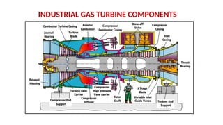
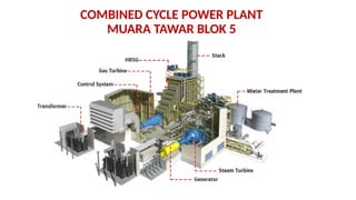
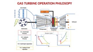
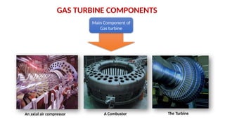
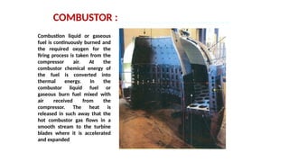
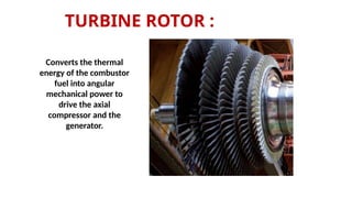
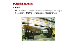
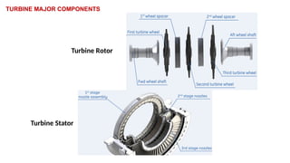
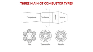
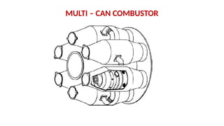
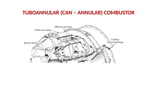
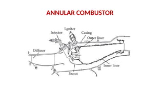
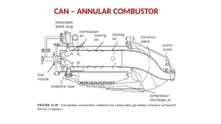
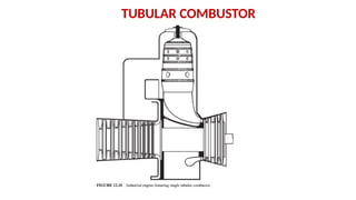
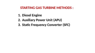
INDUSTRIAL GAS TURBINE COMPONENTS
COMBINED CYCLE POWER PLANT
MUARA TAWAR BLOK 5
GAS TURBINE OPERATION PHILOSOPY
T
P
V S
Generator Compressor
Combustion
Chamber
Turbine
Air Intake
Fuel
Exhaust
1
2 3
4 1
2
3
4
1-2 : Isentropic
Process
2-3 : Isobaric
Process
3-4 : Isentropic expansion
4-1 : Isobaric heat
rejection
Ignition
Brayton Cycle
GAS TURBINE COMPONENTS
Main Component of
Gas turbine
An axial air compressor A Combustor The Turbine
General unit Information :
• The MS9001E also known as frame 9E or PG9161E.
• Designed for power generation for either simple cycle or
combined cycle applications
• Running in 50 Hz frequency
• Output capacity is about 107 MW
• Capable to run by dual fuel (Natural Gas or liquid diesel oil) with
fuel switching capability
• Capable to running on a grid system as a base load, peaker, or
standby reserve unit
• Currently it is running by a speedtronic Mark VIe control system
GAS TURBINE UNIT MS9001E
AXIAL FLOW COMPRESSOR
The pressurized air entering
the combustion chamber is
delivered by the axial
compressor. Compressor
supplied air by the air intake
system. The air drawn in flows
from the outside to inside
through the filter element.
THE COMRESSOR ARE CONSISTING OF 2 MAJOR
COMPONENTS :
The compressor rotor
The compressor stator
It is 17 stages of axial flow compressor
with a variable Inlet guide vane. Air is
compressed to pressure ratio 12 : 1
COMBUSTOR :
Combustion liquid or gaseous
fuel is continuously burned and
the required oxygen for the
firing process is taken from the
compressor air. At the
combustor chemical energy of
the fuel is converted into
thermal energy. In the
combustor liquid fuel or
gaseous burn fuel mixed with
air received from the
compressor. The heat is
released in such away that the
hot combustor gas flows in a
smooth stream to the turbine
blades where it is accelerated
and expanded
TURBINE ROTOR :
Converts the thermal
energy of the combustor
fuel into angular
mechanical power to
drive the axial
compressor and the
generator.
TURBINE ROTOR
• Rotor
it has function to transform mechanical energy into torque
then transfer it to the compressor and the generator
TURBINE MAJOR COMPONENTS
Turbine Rotor
Turbine Stator
THE BEARING ASSEMBLY
1. Air Intake Systems
2. Lubrication Oil Systems
3. Compressor and Blowoff Systems
4. Cooling Water Systems
5. Cooling and Sealing Air Systems
6. Fuel Gas Systems
7. Ignition Fuel Systems
ANCILLARY GAS TURBINE SYSTEM COMPONENTS
AIR INTAKE SYSTEMS
The air intake system supplies
the compressor with sufficient
clean, dry air to support the
combustion process and the
cooling and sealing
requirements of the thermal
block. The air drawn in flows
from the outside to inside
through the filter element.
VARIABLE INLET GUIDE VANE
A gas turbine engine in which the angle of
the inlet guide vanes can be changed to
meet the requirements of the engine-
operating conditions. These are normally in
front of the first stage of an axial
compressor and sometimes in the
subsequent stages as well. Normally, they
are closed during engine starting and low
RPM, but they open progressively as the
RPM is increased. At low RPM, the angle of
attack of the low-pressure blades is kept
moderate to avoid stalling. Variable-inlet
guide vanes are not common in front of the
turbine
LUBE OIL SYSTEMS :
The lube oil system performs the following functions:
1.Supplies lube oil for lubrication and cooling to the
bearings of the gas turbine generator set
2.Supplies oil to power oil system
3.Supplies oil to the jacking system
LUBE OIL SYSTEMS
JACKING OIL SYSTEM
Rotor Barring System
Hydraulic Rotor Barring System
Hydraulic Rotor Barring System Function
The hydraulic rotor barring system
is used to turn the rotor before
start-up and after run-down of the
gas turbine to ensure uniform
cooling of the rotor in order to
prevent rotor bending.
POWER OIL SYSTEM
Power Oil System Function :
The power oil system supplies pressurized and filtered oil via power oil
distribution system to the protection system and to the hydraulically operated
equipment of the gas turbine under all operating conditions:
- Gas turbine hydraulic trip unit (EHSS).
- Control valves of fuel gas, fuel oil and NOX water
- Compressor variable inlet guide vanes (VIGV).
COMPRESSOR BLOW OFF SYSTEM
COOLING WATER SYSTEM
Cooling water system is a closed system and the
function of the cooling water system is :
- cooling lube oil, (indirectly cooling the bearings)
- cooling air generator (indirectly cooling the generator)
COOLING WATER SYSTEMS
COOLING AND SEALING AIR SYSTEMS
COMBUSTOR
THREE MAIN GT COMBUSTOR TYPES
MULTI – CAN COMBUSTOR
TUBOANNULAR (CAN – ANNULAR) COMBUSTOR
ANNULAR COMBUSTOR
CAN – ANNULAR COMBUSTOR
TUBULAR COMBUSTOR
STARTING GAS TURBINE METHODS :
1. Diesel Engine
2. Auxiliary Power Unit (APU)
3. Static Frequency Converter (SFC)
STATIC FREQUENCY CONVERTER
Static starting devices, also called static
frequency converter (SFC), have been utilized
to start gas turbines in gas turbine combined
cycle (GTCC) power plant, etc. In general, a gas
turbine is started using a generator functioning
as synchronous motor with single shaft
arrangement that is rotated by the
electric power fed from the SFC.
INFORMATION ABOUT WORKING PRINCIPLE OF SFC
The function of SFC transformer is to change or to
reduce the medium switchgear voltage of 6.3 kV to SFC
rating voltage 3.7 kV. This rating voltage is used as the
input voltage to the converter. Output voltage of SFC
transformer are rectified by the converter into DC
voltage which can be adjusted according to the ignition
angle α. Because this DC voltage has too ripple voltage
so it needed DC reactor to reduce the ripple on the
output converter. Then, this filtered DC voltage is
changed again to AC voltage that can be varied between
0 to 3300 volts which is then supplied to the generator
that functions as a synchronous motor for acceleration
at start-up power plant.
CARA KERJA SFC
CARA KERJA SFC
1. Tegangan jaringan diturunkan menggunakan transformer step down
hingga menjadi tegangan yang cocok untuk input inverter.
2. Converter mengkonversi tegangan AC ke DC. Output converter berupa
DC variable (bervariasi) yang artinya frekuensinya dapat diubah
tergantung pengaturan trigger thrystor pada converter
3. Tegangan DC yang dihasilkan memiliki riak. DC reactor menghilangkan
riak tersebut.
4. Inverter mengubah tegangan DC ke AC. Output inverter berupa AC
variable (bervariasi).
5. Generator berubah fungsi sebagai motor sinkron selama start up
6. Panel kontrol SFC berfungsi mengontrol converter dan inverter, dan
mengawasi sinyal error dari peralatan tersebut selama kondisi turning
(3rpm) sampai kecepatan sesuai settingnya (3000rpm).
TWIN SHAFT GAS TURBINE

Gas Turbine Components Presentation.pptx

  • 1.
  • 2.
    COMBINED CYCLE POWERPLANT MUARA TAWAR BLOK 5
  • 3.
    GAS TURBINE OPERATIONPHILOSOPY T P V S Generator Compressor Combustion Chamber Turbine Air Intake Fuel Exhaust 1 2 3 4 1 2 3 4 1-2 : Isentropic Process 2-3 : Isobaric Process 3-4 : Isentropic expansion 4-1 : Isobaric heat rejection Ignition Brayton Cycle
  • 4.
    GAS TURBINE COMPONENTS MainComponent of Gas turbine An axial air compressor A Combustor The Turbine
  • 5.
    General unit Information: • The MS9001E also known as frame 9E or PG9161E. • Designed for power generation for either simple cycle or combined cycle applications • Running in 50 Hz frequency • Output capacity is about 107 MW • Capable to run by dual fuel (Natural Gas or liquid diesel oil) with fuel switching capability • Capable to running on a grid system as a base load, peaker, or standby reserve unit • Currently it is running by a speedtronic Mark VIe control system
  • 6.
  • 7.
    AXIAL FLOW COMPRESSOR Thepressurized air entering the combustion chamber is delivered by the axial compressor. Compressor supplied air by the air intake system. The air drawn in flows from the outside to inside through the filter element.
  • 8.
    THE COMRESSOR ARECONSISTING OF 2 MAJOR COMPONENTS : The compressor rotor The compressor stator It is 17 stages of axial flow compressor with a variable Inlet guide vane. Air is compressed to pressure ratio 12 : 1
  • 9.
    COMBUSTOR : Combustion liquidor gaseous fuel is continuously burned and the required oxygen for the firing process is taken from the compressor air. At the combustor chemical energy of the fuel is converted into thermal energy. In the combustor liquid fuel or gaseous burn fuel mixed with air received from the compressor. The heat is released in such away that the hot combustor gas flows in a smooth stream to the turbine blades where it is accelerated and expanded
  • 10.
    TURBINE ROTOR : Convertsthe thermal energy of the combustor fuel into angular mechanical power to drive the axial compressor and the generator.
  • 11.
    TURBINE ROTOR • Rotor ithas function to transform mechanical energy into torque then transfer it to the compressor and the generator
  • 12.
  • 13.
  • 14.
    1. Air IntakeSystems 2. Lubrication Oil Systems 3. Compressor and Blowoff Systems 4. Cooling Water Systems 5. Cooling and Sealing Air Systems 6. Fuel Gas Systems 7. Ignition Fuel Systems ANCILLARY GAS TURBINE SYSTEM COMPONENTS
  • 15.
    AIR INTAKE SYSTEMS Theair intake system supplies the compressor with sufficient clean, dry air to support the combustion process and the cooling and sealing requirements of the thermal block. The air drawn in flows from the outside to inside through the filter element.
  • 16.
    VARIABLE INLET GUIDEVANE A gas turbine engine in which the angle of the inlet guide vanes can be changed to meet the requirements of the engine- operating conditions. These are normally in front of the first stage of an axial compressor and sometimes in the subsequent stages as well. Normally, they are closed during engine starting and low RPM, but they open progressively as the RPM is increased. At low RPM, the angle of attack of the low-pressure blades is kept moderate to avoid stalling. Variable-inlet guide vanes are not common in front of the turbine
  • 17.
    LUBE OIL SYSTEMS: The lube oil system performs the following functions: 1.Supplies lube oil for lubrication and cooling to the bearings of the gas turbine generator set 2.Supplies oil to power oil system 3.Supplies oil to the jacking system
  • 18.
  • 19.
  • 20.
  • 21.
    Hydraulic Rotor BarringSystem Hydraulic Rotor Barring System Function The hydraulic rotor barring system is used to turn the rotor before start-up and after run-down of the gas turbine to ensure uniform cooling of the rotor in order to prevent rotor bending.
  • 22.
    POWER OIL SYSTEM PowerOil System Function : The power oil system supplies pressurized and filtered oil via power oil distribution system to the protection system and to the hydraulically operated equipment of the gas turbine under all operating conditions: - Gas turbine hydraulic trip unit (EHSS). - Control valves of fuel gas, fuel oil and NOX water - Compressor variable inlet guide vanes (VIGV).
  • 23.
  • 24.
    COOLING WATER SYSTEM Coolingwater system is a closed system and the function of the cooling water system is : - cooling lube oil, (indirectly cooling the bearings) - cooling air generator (indirectly cooling the generator)
  • 25.
  • 26.
  • 27.
  • 28.
  • 29.
    THREE MAIN GTCOMBUSTOR TYPES
  • 30.
    MULTI – CANCOMBUSTOR
  • 31.
    TUBOANNULAR (CAN –ANNULAR) COMBUSTOR
  • 32.
  • 33.
    CAN – ANNULARCOMBUSTOR
  • 34.
  • 35.
    STARTING GAS TURBINEMETHODS : 1. Diesel Engine 2. Auxiliary Power Unit (APU) 3. Static Frequency Converter (SFC)
  • 36.
    STATIC FREQUENCY CONVERTER Staticstarting devices, also called static frequency converter (SFC), have been utilized to start gas turbines in gas turbine combined cycle (GTCC) power plant, etc. In general, a gas turbine is started using a generator functioning as synchronous motor with single shaft arrangement that is rotated by the electric power fed from the SFC.
  • 37.
    INFORMATION ABOUT WORKINGPRINCIPLE OF SFC The function of SFC transformer is to change or to reduce the medium switchgear voltage of 6.3 kV to SFC rating voltage 3.7 kV. This rating voltage is used as the input voltage to the converter. Output voltage of SFC transformer are rectified by the converter into DC voltage which can be adjusted according to the ignition angle α. Because this DC voltage has too ripple voltage so it needed DC reactor to reduce the ripple on the output converter. Then, this filtered DC voltage is changed again to AC voltage that can be varied between 0 to 3300 volts which is then supplied to the generator that functions as a synchronous motor for acceleration at start-up power plant.
  • 38.
  • 39.
    CARA KERJA SFC 1.Tegangan jaringan diturunkan menggunakan transformer step down hingga menjadi tegangan yang cocok untuk input inverter. 2. Converter mengkonversi tegangan AC ke DC. Output converter berupa DC variable (bervariasi) yang artinya frekuensinya dapat diubah tergantung pengaturan trigger thrystor pada converter 3. Tegangan DC yang dihasilkan memiliki riak. DC reactor menghilangkan riak tersebut. 4. Inverter mengubah tegangan DC ke AC. Output inverter berupa AC variable (bervariasi). 5. Generator berubah fungsi sebagai motor sinkron selama start up 6. Panel kontrol SFC berfungsi mengontrol converter dan inverter, dan mengawasi sinyal error dari peralatan tersebut selama kondisi turning (3rpm) sampai kecepatan sesuai settingnya (3000rpm).
  • 40.
  • 41.