Downloaded 12 times


![10
Article numbers
Article numbers
Conventional design Long version
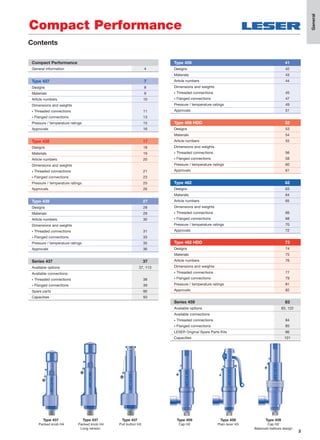
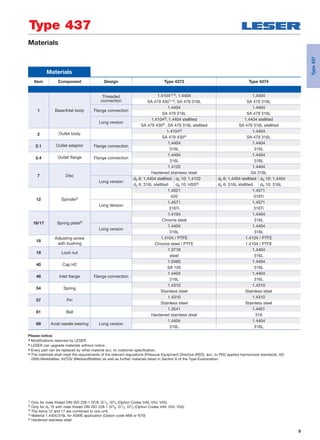
Actual Orifice diameter d0 [mm] 10 6 10
Actual Orifice area A0 [mm2] 78.5 28.3 78.5
Actual Orifice diameter d0 [inch] 0.394 0.236 0.394
Actual Orifice area A0 [inch2] 0.122 0.044 0.122
Base / Inlet body material: 1.4104 (430)1)
H2 Art. No. 4373.2)
2602 2622 2612
H3 Art. No. 4373.2)
pmax. = 16 barg
2603 – –
H4 Art. No. 4373.2)
2604 2624 2614
p [barg] S/G/L 0.1 – 93 S/G 180 – 365 S/G/L 93 –180
p [psig] S/G/L 1.5 – 1349 S/G 2611 – 5294 S/G/L 1349 – 2611
Base / Inlet body material: 1.4404 (316L)
H2 Art. No. 4374. 3142 3122 3152
H4 Art. No. 4374. 3144 3124 3154
p [barg] S/G/L 0.1 – 68 S/G 180 – 330 S/G/L 68 –180
p [psig] S/G/L 1.5 – 986 S/G 2611 – 4786 S/G/L 986 – 2611
Type 437
1) Material 1.4404/316L for ASME application (Option code N68 or N70).
2) Type 4373 should not be selected when a „stainless steel“ valve is required due to corrosive medium.
Metal seat
Type437](https://image.slidesharecdn.com/39dd659d-0f12-40d3-8ff4-3594fb05bf13-160314115249/85/LESER-Safety-Valve-Compact-Performance-Extended-Catalog-EN-10-320.jpg)
![11
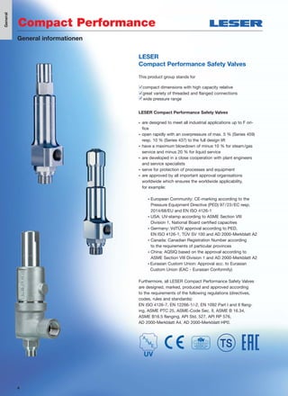
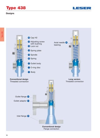
Dimensions and weights – Threaded connections [Metric units]
Conventional design – female thread Conventional design – male thread Long version – male threadRequired installation diameter
d
Threaded connections
Size Outlet body
Conventional design Long version
1/2" 3/4" 1" 1/2" 3/4" 1" 1/2" 3/4" 1"
Actual Orifice diameter d0 [mm] 10 10 10 6 6 6 10 10 10
Actual Orifice area A0 [mm2] 78.5 78.5 78.5 28.3 28.3 28.3 78.5 78.5 78.5
Weight [kg] 1.2 1.6 1.6 1.4 2.1 2.1 1.4 2.1 2.1
Required installation diameter d [mm] 65 80 80 65 80 80 65 80 80
Inlet thread female
Size outlet body
Conventional design Long version
1/2" 3/4" 1" 1/2" 3/4" 1" 1/2" 3/4" 1"
Center to face [mm]
DIN ISO 228-1 G
Inlet 1/2" a 46 46 49 46 46 49 46 46 49
ISO 7-1/BS 21 Rc
ASME B1.20.1 NPT Inlet 3/4", 1" a 56 56 59 56 56 59 56 56 59
Outlet b 30 37 37 30 37 37 30 37 37
Height [mm]
Inlet 1/2" H max. 209 209 212 230 230 233 230 230 233
Inlet 3/4", 1" H max. 219 219 222 240 240 243 240 240 243
Inlet thread male
Size outlet body
Conventional design Long version
1/2" 3/4" 1" 1/2" 3/4" 1" 1/2" 3/4" 1"
Center to face [mm]
DIN ISO 228-1 G
Inlet a 33 33 36 33 33 36 33 33 36
Outlet b 30 37 37 30 37 37 30 37 37
ISO 7-1/BS 21 R
Inlet a 31 31 34 31 31 34 31 31 34
ASME B1.20.1 NPT
Outlet b 30 37 37 30 37 37 30 37 37
Height [mm]
Size inlet thread
Conventional design Long version
3/8" 1/2" 3/4" 1" 3/8" 1/2" 3/4" 1"
DIN ISO 228-1 G H max. 208 210 212 217 229 231 233 238
ISO 7-1/BS 21 R H max. – 213 214 220 – 234 235 241
ASME B1.20.1 NPT H max. – 216 216 224 – 237 237 245
Length of screwed end c [mm]
Size inlet thread 3/8" 1/2" 3/4" 1"
DIN ISO 228-1 G 12 14 16 18
ISO 7-1/BS 21 R – 19 20 23
ASME B1.20.1 NPT – 22 22 27
Type 437
Type437](https://image.slidesharecdn.com/39dd659d-0f12-40d3-8ff4-3594fb05bf13-160314115249/85/LESER-Safety-Valve-Compact-Performance-Extended-Catalog-EN-11-320.jpg)
![12
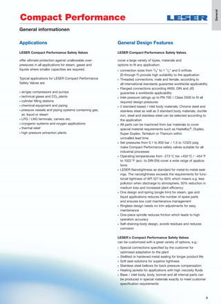
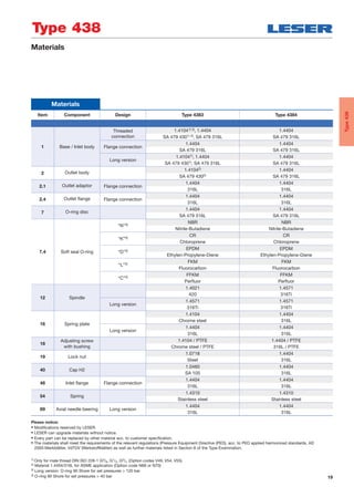
Dimensions and weights – Threaded connections [US units]
Conventional design – female thread Conventional design – male thread Long version – male threadRequired installation diameter
d
Threaded connections
Size Outlet body
Conventional design Long version
1/2" 3/4" 1" 1/2" 3/4" 1" 1/2" 3/4" 1"
Actual Orifice diameter d0 [inch] 0.394 0.394 0.394 0.236 0.236 0.236 0.394 0.394 0.394
Actual Orifice area A0 [inch2] 0.122 0.122 0.122 0.044 0.044 0.044 0.122 0.122 0.122
Weight [lbs] 2.6 3.5 3.5 3.1 4.6 4.6 3.1 4.6 4.6
Required installation diameter d [inch] 29/16 35/32 35/32 29/16 35/32 35/32 29/16 35/32 35/32
Inlet thread female
Size outlet body
Conventional design Long version
1/2" 3/4" 1" 1/2" 3/4" 1" 1/2" 3/4" 1"
Center to face [inch]
DIN ISO 228-1 G
Inlet 1/2" a 113/16 113/16 115/16 113/16 113/16 115/16 113/16 113/16 115/16
ISO 7-1/BS 21 Rc
ASME B1.20.1 NPT Inlet 3/4", 1" a 27/32 27/32 25/16 27/32 27/32 25/16 27/32 27/32 25/16
Outlet b 13/16 115/32 115/32 13/16 115/32 115/32 13/16 115/32 115/32
Height [inch]
Inlet 1/2" H max. 87/32 87/32 811/32 91/16 91/16 93/16 91/16 91/16 93/16
Inlet 3/4", 1" H max. 85/8 85/8 83/4 97/16 97/16 99/16 97/16 97/16 99/16
Inlet thread male
Size outlet body
Conventional design Long version
1/2" 3/4" 1" 1/2" 3/4" 1" 1/2" 3/4" 1"
Center to face [inch]
DIN ISO 228-1 G
Inlet a 15/16 15/16 113/32 15/16 15/16 113/32 15/16 15/16 113/32
Outlet b 13/16 115/32 115/32 13/16 115/32 115/32 13/16 115/32 115/32
ISO 7-1/BS 21 R
Inlet a 17/32 17/32 111/32 17/32 17/32 111/32 17/32 17/32 111/32
ASME B1.20.1 NPT
Outlet b 13/16 115/32 115/32 13/16 115/32 115/32 13/16 115/32 115/32
Height [inch]
Size inlet thread
Conventional design Long version
3/8" 1/2" 3/4" 1" 3/8" 1/2" 3/4" 1"
DIN ISO 228-1 G H max. 83/16 81/4 811/32 817/32 9 93/32 95/32 93/8
ISO 7-1/BS 21 R H max. – 83/8 813/32 821/32 – 97/32 91/4 915/32
ASME B1.20.1 NPT H max. – 81/2 81/2 813/16 – 95/16 95/16 921/32
Length of screwed end c [inch]
Size inlet thread 3/8" 1/2" 3/4" 1"
DIN ISO 228-1 G 15/32
9/16
5/8
23/32
ISO 7-1/BS 21 R – 3/4
25/32
29/32
ASME B1.20.1 NPT – 7/8
7/8 11/16
Type 437
Type437](https://image.slidesharecdn.com/39dd659d-0f12-40d3-8ff4-3594fb05bf13-160314115249/85/LESER-Safety-Valve-Compact-Performance-Extended-Catalog-EN-12-320.jpg)
![13
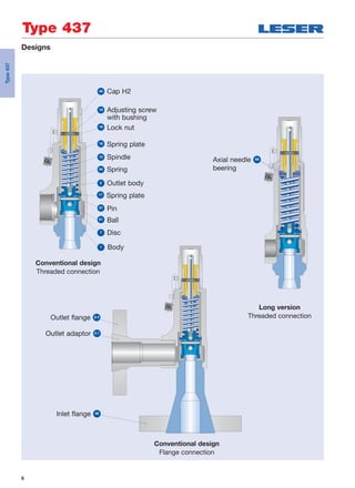
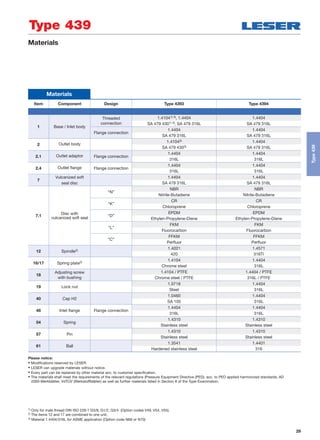
Dimensions and weights – Flanged connections [Metric units]
Flanged connections
Conventional design Long version
Actual Orifice diameter d0 [mm] 10 6 10
Actual Orifice area A0 [mm2] 78.5 28.3 78.5
DIN EN 1092-1 (Available flange sizes refer to page 04/05)
Flange rating class PN 40
Center to face [mm] Inlet a 103 103 103
Outlet b 100 100 100
Height [mm] H max. 263 284 284
Flange rating class ≥ PN 160
Center to face [mm] Inlet a 103 103 103
Outlet b 100 100 100
Height [mm] H max. 266 287 287
ASME B 16.5 (Available flange sizes refer to page 04/05)
Flange rating class 150
Center to face [mm] Inlet a 103 103 103
Outlet b 100 100 100
Height [mm] H max. 263 284 284
Flange rating class ≥ 300
Center to face [mm] Inlet a 103 103 103
Outlet b 100 100 100
Height [mm] H max. 266 287 287
Note The outlet dimension b can differ at special combinations of nominal diameter and pressure range if flanged connections are used at the inlet and outlet.
Special dimensions are possible. More information at sales@leser.com
Weight
To calculate the total weight use the formula: mT = mN + mF(Inlet) + mF (Outlet)
Weight net [kg]
2.4 2.8 2.8(without inlet and outlet flange) mN
Flange dimensions
DIN EN 1092-1 / Flange rating PN ASME B16.5 / Flange rating
Size 40 100 160 250 320 400 Size 150 300 600 900 1500 2500
DN 15 NPS 1/2"
Flange thickness [mm] s 18 – 22 28 28 30 14 18 18 26 26 30.2
Weight slip on flange [kg] mF 0.8 – 1.2 2.5 2.5 3.6 0.6 0.9 0.9 2.1 2.1 3
DN 20 NPS 3/4"
Flange thickness [mm] s 20 22 – – – – 15 18 18 25.4 25.4 32
Weight slip on flange [kg] mF 1.1 1.3 – – – – 0.8 1.4 1.4 2.3 2.3 3.5
DN 25 NPS 1"
Flange thickness [mm] s 22 – 26 30 36 40 17 21.5 21.5 32.5 32.5 40
Weight slip on flange [kg] mF 1.3 – 2.6 3.5 5 7.5 1 2.1 21 4.1 4.1 5.1
Long versionConventional design
b
a
s
s s
s
Type 437
Type437](https://image.slidesharecdn.com/39dd659d-0f12-40d3-8ff4-3594fb05bf13-160314115249/85/LESER-Safety-Valve-Compact-Performance-Extended-Catalog-EN-13-320.jpg)
![14
Dimensions and weights – Flanged connections [US units]
Flanged connections
Conventional design Long version
Actual Orifice diameter d0 [inch] 0.394 0.236 0.394
Actual Orifice area A0 [inch2] 0.122 0.044 0.122
DIN EN 1092-1 (Available flange sizes refer to page 39)
Flange rating PN 40
Center to face [inch] Inlet a 41/16 41/16 41/16
Outlet b 315/16 315/16 315/16
Height [inch] H max. 1011/32 113/16 113/16
Flange rating ≥ PN 160
Center to face [inch] Inlet a 41/16 41/16 41/16
Outlet b 315/16 315/16 315/16
Height [inch] H max. 1015/32 115/16 115/16
ASME B 16.5 (Available flange sizes refer to page 39)
Flange rating class 150
Center to face [inch] Inlet a 41/16 41/16 41/16
Outlet b 315/16 315/16 315/16
Height [inch] H max. 1011/32 113/16 113/16
Flange rating class ≥ 300
Center to face [inch] Inlet a 41/16 41/16 41/16
Outlet b 315/16 315/16 315/16
Height [inch] H max. 1015/32 115/16 115/16
Note The outlet dimension b can differ at special combinations of nominal diameter and pressure range if flanged connections are used at the inlet and outlet.
Special dimensions are possible. More information at sales@leser.com
Weight
To calculate the total weight use the formula: mT = mN + mF (Inlet) + mF (Outlet)
Weight net [lbs]
5.3 6.2 6.2(without inlet and outlet flange) mN
Flange dimensions
DIN EN 1092-1 / Flange rating PN ASME B16.5 / Flange rating
Size 40 100 160 250 320 400 Size 150 300 600 900 1500 2500
DN 15 NPS 1/2"
Flange thickness [inch] s 23/32 – 7/8
23/32 13/32 13/16
9/16
23/32
23/32 13/32 13/32 13/16
Weight slip on flange [lbs] mF 1.8 – 2.6 5.5 5.5 7.9 1.3 2.0 2.0 4.6 4.6 6.6
DN 20 NPS 3/4"
Flange thickness [inch] s 25/32
7/8 – – – – 19/32
23/32
23/32 1 1 11/4
Weight slip on flange [lbs] mF 2.4 2.9 – – – – 1.8 3.1 3.1 5.0 5.0 7.7
DN 25 NPS 1"
Flange thickness [inch] s 7/8 – 11/32 13/16 113/32 19/16
21/32
27/32
27/32 19/32 19/32 19/16
Weight slip on flange [lbs] mF 2.9 – 5.7 7.7 11.0 16.5 2.2 4.6 4.6 9.0 9.0 11.2
Long versionConventional design
b
a
s
s s
s
Type 437
Type437](https://image.slidesharecdn.com/39dd659d-0f12-40d3-8ff4-3594fb05bf13-160314115249/85/LESER-Safety-Valve-Compact-Performance-Extended-Catalog-EN-14-320.jpg)
![15
Metric units
Actual Orifice diameter d0 [mm] 6 10
Actual Orifice area A0 [mm2] 28.3 78.5
Body material: 1.4104 (430)
Base / Connection size 3/8" 1/2" 3/4" 1" 3/8" 1/2" 3/4" 1"
Inlet Body Pressure rating PN 400 PN 320
Outlet body Pressure rating PN 160 PN 160
Minimum
p [barg] S/G/L 180 [S/G only] 0.1set pressure
Maximum
p [barg] S/G/L 365 [S/G only]
16 [only H3]
180set pressure
Temperature min [°C ] -10
acc. to DIN EN max [°C ] +220
Temperature min [°C ] -29
acc. to ASME max [°C ] +220
Body material: 1.4404 (316L)
Base / Connection size 3/8" 1/2" 3/4" 1" 3 /8" 1/2" 3/4" 1"
Inlet Body Pressure rating PN 400 PN 320
Outlet body Pressure rating PN 160 PN 160
Minimum
p [barg] S/G/L 180 [S/G only] 0.1
set pressure
Maximum
p [barg] S/G/L 365 [S/G only] 180
set pressure
Temperature min [°C ] -270
acc. to DIN EN max [°C ] +280
Temperature min [°C ] -268
acc. to ASME max [°C ] +280
Pressure/temperature ratings [Metric units + US units]
US units
Actual Orifice diameter d0 [inch] 0,236 0,394
Actual Orifice area A0 [inch2
] 0,044 0,122
Body material: 1.4104 (430)
Base /
Connection size 3/8" 1/2" 3/4" 1" 3/8" 1/2" 3/4" 1"
Inlet Body
Minimum
p [psig] S/G/L 2611 1.5
set pressure
Maximum
p [psig] S/G/L 5294
145 [only H3]
2611set pressure
Temperature min [°F ] +14
acc. to DIN EN max [°F ] +428
Temperature min [°F ] -20
acc. to ASME max [°F ] +428
Body material: 1.4404 (316L)
Base /
Connection size 3/8" 1/2" 3/4" 1" 3/8" 1/2" 3/4" 1"
Inlet Body
Minimum
p [psig] S/G/L 2611 1.5
set pressure
Maximum
p [psig] S/G/L 5294 2611
set pressure
Temperature min [°F ] -450
acc. to DIN EN max [°F ] +536
Temperature min [°F ] -450
acc. to ASME max [°F ] +536
Type 437
Type437](https://image.slidesharecdn.com/39dd659d-0f12-40d3-8ff4-3594fb05bf13-160314115249/85/LESER-Safety-Valve-Compact-Performance-Extended-Catalog-EN-15-320.jpg)
![16
Type 437
Approvals
Approvals
Actual Orifice diameter d0 [mm] 6 10
Actual Orifice area A0 [mm2] 28.3 78.5
Actual Orifice diameter d0 [inch] 0.236 0.394
Actual Orifice area A0 [inch2] 0.044 0.122
Europe Coefficient of discharge Kdr
PED/DIN EN ISO 4126-1
12/2013
Approval No. 072020111Z0008/0/21
S/G 0.72 0.50
L – 0.35
Germany Coefficient of discharge w
PED/AD 2000-Merkblatt A2
07/2012
Approval No. TÜV SV 980
S/G 0.72 0.50
L – 0.35
United States Coefficient of discharge K
ASME Sec. VIII Div. 1
Zulassungs-Nr. – M 37213
D/G – 0.458
Zulassungs-Nr. – M 37189
F – 0.333
Canada Coefficient of discharge K
CRN
Approval No. The current approval no. can be found at www.leser.com
S/G – 0.458
L – 0.333
China Coefficient of discharge w
AQSIQ
Approval No. The current approval no. can be found at www.leser.com
S/G 0.72 0.50
L – 0.35
Eurasian Custom Union Coefficient of discharge w
EAC
Approval No. The current approval no. can be found at www.leser.com
S/G 0.72 0.50
L – 0.35
Classification societies Homepage
Bureau Veritas BV www.bureauveritas.com
The valid certification number is changed with every reneval.
A sample certificate including the valid certification number
can be found at www.leser.com
DNV GL www.dnvgl.com
Lloyd‘s Register EMEA LREMEA www.lr.org
Registro Italiano Navale RINA www.rina.org
U.S. Coast Guard U.S.C.G www.uscg.org
Rated slope
Within the capacity certification according to ASME Sec. VIII Div. 1
the coefficients of discharge for Series 437 are issued as “rated slope
values” instead of K values. Rated slope values can be converted into
K values. The table above shows the converted K values. The original
rated slope values are listed in the table below.
FluidFluid Rated slope Type 437Rated slope Type 437
S 2.86 lb / hr / PSIA
G 1.02 SCFM / PSIA
L 1.54 GPM √PSID
Type437](https://image.slidesharecdn.com/39dd659d-0f12-40d3-8ff4-3594fb05bf13-160314115249/85/LESER-Safety-Valve-Compact-Performance-Extended-Catalog-EN-16-320.jpg)

![20
Type 438
Article numbers
Article numbers
Conventional design Long version
Actual Orifice diameter d0 [mm] 10 10
Actual Orifice area A0 [mm2] 78.5 78.5
Actual Orifice diameter d0 [inch] 0.394 0.394
Actual Orifice area A0 [inch2] 0.122 0.122
O-ring material NBR “N” J30 NBR “N” J303)
CR “K” J21 CR “K” J213)
EPDM “D” J22 EPDM “D” J223)
FKM “L” J23 FKM “L” J233)
FFKM “C” J204) FFKM “C” J204)
Base/Inlet body material: 1.4104 (430)1)
H2 Art. No. 4383.2) 2862 2872
H3 Art. No. 4383.2)
pmax = 16 barg
2863 –
H4 Art. No. 4383.2) 2864 2874
p [barg] S/G/L 5 – 93 93 – 180
p [psig] S/G/L 72.5 – 1349 1349 – 2611
Base/Inlet body material: 1.4404 (316L)
H2 Art. No. 4384. 2982 2992
H4 Art. No. 4384. 2984 2994
p [barg] S/G/L 5 – 68 68 – 180
p [psig] S/G/L 72.5 – 986 986 – 2611
1) Material 1.4404/316L for ASME application (Option code N68 or N70)
2) Type 4383 should not be selected when a „stainless steel“ valve is required due to corrosive medium.
3) O-ring 90 Shore for set pressures > 120 bar
4) O-ring 90 Shore for set pressures > 40 bar
O-ring disc
Type438](https://image.slidesharecdn.com/39dd659d-0f12-40d3-8ff4-3594fb05bf13-160314115249/85/LESER-Safety-Valve-Compact-Performance-Extended-Catalog-EN-20-320.jpg)
![21
Type 438
Dimensions and weights – Threaded connections [Metric units]
Threaded connections
Size Outlet body
Conventional design Long version
1/2" 3/4" 1" 1/2" 3/4" 1"
Actual Orifice diameter d0 [mm] 10 10 10 10 10 10
Actual Orifice area A0 [mm2] 78.5 78.5 78.5 78.5 78.5 78.5
Weight [kg] 1.2 1.6 1.6 1.4 2.1 2.1
Required installation diameter d [mm] 65 80 80 65 80 80
Inlet thread female
Size outlet body
Conventional design Long version
1/2" 3/4" 1" 1/2" 3/4" 1"
Center to face [mm]
DIN ISO 228-1 G
Inlet 1/2" a 46 46 49 46 46 49
ISO 7-1/BS 21 Rc
ASME B1.20.1 NPT Inlet 3/4", 1" a 56 56 59 56 56 59
Outlet b 30 37 37 30 37 37
Height [mm]
Inlet 1/2" H max. 209 209 212 230 230 233
Inlet 3/4", 1" H max. 219 219 222 240 240 243
Inlet thread male
Size outlet body
Conventional design Long version
1/2" 3/4" 1" 1/2" 3/4" 1"
Center to face [mm]
DIN ISO 228-1 G
Inlet a 33 33 36 33 33 36
Outlet b 30 37 37 30 37 37
ISO 7-1/BS 21 R
Inlet a 31 31 34 31 31 34
ASME B1.20.1 NPT
Outlet b 30 37 37 30 37 37
Height [mm]
Size inlet thread
Conventional design Long version
3/8" 1/2" 3/4" 1" 3/8" 1/2" 3/4" 1"
DIN ISO 228-1 G H max. 208 210 212 217 229 231 233 238
ISO 7-1/BS 21 R H max. – 213 214 220 – 234 235 241
ASME B1.20.1 NPT H max. – 216 216 224 – 237 237 245
Length of screwed end c [mm]
Size inlet thread 3/8" 1/2" 3/4" 1"
DIN ISO 228-1 G 12 14 16 18
ISO 7-1/BS 21 R – 19 20 23
ASME B1.20.1 NPT – 22 22 27
d
Required installation diameter Conventional design – female thread Conventional design – male thread Long version – male thread
Type438](https://image.slidesharecdn.com/39dd659d-0f12-40d3-8ff4-3594fb05bf13-160314115249/85/LESER-Safety-Valve-Compact-Performance-Extended-Catalog-EN-21-320.jpg)
![22
Conventional design – female thread Conventional design – male thread Long version – male threadRequired installation diameter
d
Threaded connections
Size Outlet body
Conventional design Long version
1/2" 3/4" 1" 1/2" 3/4" 1"
Actual Orifice diameter d0 [inch] 0.394 0.394 0.394 0.394 0.394 0.394
Actual Orifice area A0 [inch2] 0.122 0.122 0.122 0.122 0.122 0.122
Weight [lbs] 2.6 3.5 3.5 3.1 4.6 4.6
Required installation diameter d [inch] 29/16 35/32 35/32 29/16 35/32 35/32
Inlet thread female
Size outlet body
Conventional design Long version
1/2" 3/4" 1" 1/2" 3/4" 1"
Center to face [inch]
DIN ISO 228-1 G
Inlet 1/2" a 113/16 113/16 115/16 113/16 113/16 115/16
ISO 7-1/BS 21 Rc
ASME B1.20.1 NPT Inlet 3/4", 1" a 27/32 27/32 25/16 27/32 27/32 25/16
Outlet b 13/16 115/32 115/32 13/16 115/32 115/32
Height [inch]
Inlet 1/2" H max. 87/32 87/32 811/32 91/16 91/16 93/16
Inlet 3/4", 1" H max. 85/8 85/8 83/4 97/16 97/16 99/16
Inlet thread male
Size outlet body
Conventional design Long version
1/2" 3/4" 1" 1/2" 3/4" 1"
Center to face [inch]
DIN ISO 228-1 G
Inlet a 15/16 15/16 113/32 15/16 15/16 113/32
Outlet b 13/16 115/32 115/32 13/16 115/32 115/32
ISO 7-1/BS 21 R
Inlet a 17/32 17/32 111/32 17/32 17/32 111/32
ASME B1.20.1 NPT
Outlet b 13/16 115/32 115/32 13/16 115/32 115/32
Height [inch]
Size inlet thread
Conventional design Long version
3/8" 1/2" 3/4" 1" 3/8" 1/2" 3/4" 1"
DIN ISO 228-1 G H max. 83/16 81/4 811/32 817/32 9 93/32 95/32 93/8
ISO 7-1/BS 21 R H max. – 83/8 813/32 821/32 – 97/32 91/4 915/32
ASME B1.20.1 NPT H max. – 81/2 81/2 813/16 – 95/16 95/16 921/32
Length of screwed end c [inch]
Size inlet thread 3/8" 1/2" 3/4" 1"
DIN ISO 228-1 G 15/32
9/16
5/8
23/32
ISO 7-1/BS 21 R – 3/4
25/32
29/32
ASME B1.20.1 NPT – 7/8
7/8
11/16
Dimensions and weights – Threaded connections [US units]
Type 438
Type438](https://image.slidesharecdn.com/39dd659d-0f12-40d3-8ff4-3594fb05bf13-160314115249/85/LESER-Safety-Valve-Compact-Performance-Extended-Catalog-EN-22-320.jpg)
![23
Flanged connections
Conventional design Long version
Actual Orifice diameter d0 [mm] 10 10
Actual Orifice area A0 [mm2] 78.5 78.5
DIN EN 1092-1
Flange rating PN 40
Center to face [mm] Inlet a 103 103
Outlet b 100 100
Height [mm] H max. 263 284
Flange rating ≥ PN 160
Center to face [mm] Inlet a 103 103
Outlet b 100 100
Height [mm] H max. 266 287
ASME B 16.5
Flange rating class 150
Center to face [mm] Inlet a 103 103
Outlet b 100 100
Height [mm] H max. 263 284
Flange rating class ≥ 300
Center to face [mm] Inlet a 103 103
Outlet b 100 100
Height [mm] H max. 266 287
Weight
For the calculation of the total weight please use the Formular: WT = WN + WF (Inlet) + WF (Outlet)
Weight net [kg]
2.4 2.8
(without inlet and outlet flange) WN
Flange dimensions and availability
DIN EN 1092-1 / Flange rating PN ASME B16.5 / Flange rating class
Size 40 100 160 250 320 400 Size 150 300 600 900 1500 2500
DN 15 NPS 1/2"
Flange thickness [mm] s 18 – 22 28 28 30 14 18 18 26 26 30.2
Weight slip on flange [kg] WF 0.8 – 1.2 2.5 2.5 3.6 0.6 0.9 2.0 2.1 2.1 3
DN 20 NPS 3/4"
Flange thickness [mm] s 20 22 – – – – 15 18 18 25.4 25.4 32
Weight slip on flange [kg] WF 1.1 1.3 – – – – 0.8 1.4 1.4 2.3 2.3 3.5
DN 25 NPS 1"
Flange thickness [mm] s 22 – 26 30 36 40 17 21.5 21.5 32.5 32.5 40
Weight slip on flange [kg] WF 1.3 – 2.6 3.5 5 7.5 1 2.1 2.1 4.1 4.1 5.1
Long versionConventional design
b
a
s
s
s
s
Type 438
Dimensions and weights – Flanged connections [Metric units]
Type438](https://image.slidesharecdn.com/39dd659d-0f12-40d3-8ff4-3594fb05bf13-160314115249/85/LESER-Safety-Valve-Compact-Performance-Extended-Catalog-EN-23-320.jpg)
![24
Flanged connections
Conventional design Long version
Actual Orifice diameter d0 [inch] 0.394 0.394
Actual Orifice area A0 [inch2] 0.122 0.122
DIN EN 1092-1 (Available flange sizes refer to page 04/05)
Flange rating PN 40
Center to face [inch] Inlet a 41/16 41/16
Outlet b 315/16 315/16
Height [inch] H max. 1011/32 103/16
Flange rating ≥ PN 160
Center to face [inch] Inlet a 41/16 41/16
Outlet b 315/16 315/16
Height [inch] H max. 1015/32 115/16
ASME B 16.5 (Available flange sizes refer to page 04/05)
Flange rating class 150
Center to face [inch] Inlet a 41/16 41/16
Outlet b 315/16 315/16
Height [inch] H max. 1011/32 113/16
Flange rating class ≥ 300
Center to face [inch] Inlet a 41/16 41/16
Outlet b 315/16 315/16
Height [inch] H max. 1015/32 115/16
Weight
For the calculation of the total weight please use the Formular: WT = WN + WF (Inlet) + WF (Outlet)
Weight net [lbs]
5.3 6.2
(without inlet and outlet flange) WN
Flange dimensions and availability
DIN EN 1092-1 / Flange rating PN ASME B16.5 / Flange rating class
Size 40 100 160 250 320 400 Size 150 300 600 900 1500 2500
DN 15 NPS 1/2"
Flange thickness [inch] s 23/32 – 7/8 13/32 13/32 16/32
9/16
23/32
23/32 11/32 11/32 16/32
Weight slip on flange [lbs] WF 1.8 – 2.6 5.5 5.5 7.9 1.3 2.0 2.0 4.6 4.6 6.6
DN 20 NPS 3/4"
Flange thickness [inch] s 25/32
28/32 – – – – 19/32
23/32
23/32 1 1 18/32
Weight slip on flange [lbs] WF 2.4 2.9 – – – – 1.8 3.1 3.1 5.0 5.0 7.7
DN 25 NPS 1"
Flange thickness [inch] s 7/8 – 11/32 16/32 113/32 118/32
21/32
27/32
27/32 19/32 19/32 118/32
Weight slip on flange [lbs] WF 2.9 – 5.7 7.7 11.0 16.5 2.2 4.6 4.6 9.0 9.0 11.2
Long versionConventional design
b
a
s
s s
s
Type 438
Dimensions and weights – Flanged connections [US units]
Type438](https://image.slidesharecdn.com/39dd659d-0f12-40d3-8ff4-3594fb05bf13-160314115249/85/LESER-Safety-Valve-Compact-Performance-Extended-Catalog-EN-24-320.jpg)
![25
Pressure/temperature ratings [Metric units + US units]
Metric units
Conventional design Long version
Actual Orifice diameter d0 [mm] 10 10
Actual Orifice Area A0 [mm2] 78.5 78.5
Body material: 1.4104 (430)
Base / Connection size 3/8" 1/2" 3/4" 1" 3/8" 1/2" 3/4" 1"
Inlet Body Pressure rating PN 250 PN 250
Outlet body Pressure rating PN 160 PN 160
Minimum
p [barg] S/G/L 5 93set pressure
Maximum
p [barg] S/G/L 16 [only H3]
93
180set pressure
Temperature min [°C ] -10 -10
acc. to DIN EN max [°C ] +150 +150
Temperature min [°C ] -29 -29
acc. to ASME max [°C ] +150 +150
Body material: 1.4404 (316L)
Base / Connection size 3/8" 1/2" 3/4" 1" 3/8" 1/2" 3/4" 1"
Inlet Body Pressure rating PN 250 PN 250
Outlet body Pressure rating PN 160 PN 160
Minimum
p [barg] S/G/L 5 68
set pressure
Maximum
p [barg] S/G/L 68 180
set pressure
Temperature min [°C ] -45 -45
acc. to DIN EN max [°C ] +150 +150
Temperature min [°C ] -45 -45
acc. to ASME max [°C ] +150 +150
US units
Conventional design Long version
Actual Orifice diameter d0 [inch] 0.394 0.394
Actual Orifice area A0 [inch2
] 0.122 0.122
Body material: 1.4104 (430)
Base /
Connection size 3/8" 1/2" 3/4" 1" 3/8" 1/2" 3/4" 1"
Inlet Body
Minimum
p [psig] S/G/L 72.5 1349
set pressure
Maximum
p [psig] S/G/L 232 [only H3]
1349
2611
set pressure
Temperature min [°F ] +14 +14
acc. to DIN EN max [°F ] +302 +302
Temperature min [°F ] -20 -20
acc. to ASME max [°F ] +302 +302
Body material: 1.4404 (316L)
Base /
Connection size 3/8" 1/2" 3/4" 1" 3/8" 1/2" 3/4" 1"
Inlet Body
Minimum
p [psig] S/G/L 72.5 986
set pressure
Maximum
p [psig] S/G/L 986 2611
set pressure
Temperature min [°F ] -49 -49
acc. to DIN EN max [°F ] +302 +302
Temperature min [°F ] -49 -49
acc. to ASME max [°F ] +302 +302
1) The temperature is limited by soft seal material. The stated values are valid for EPDM.
Type 438
Type438](https://image.slidesharecdn.com/39dd659d-0f12-40d3-8ff4-3594fb05bf13-160314115249/85/LESER-Safety-Valve-Compact-Performance-Extended-Catalog-EN-25-320.jpg)
![26
Approvals
Approvals
Actual Orifice diameter d0 [mm] 10
Actual Orifice area A0 [mm2] 78.5
Actual Orifice diameter d0 [inch] 0.394
Actual Orifice area A0 [inch2] 0.122
Europe Coefficient of discharge Kdr
PED / DIN EN ISO 4126-1
12/2013
Approval No. 072020111Z0008/0/21
S/G 0.40
L 0.33
Germany Coefficient of discharge w
PED / AD 2000-Merkblatt A2
07/2012
Approval No. TÜV SV 980
S/G 0.40
L 0.33
United States Coefficient of discharge K
ASME Sec. VIII Div. 1
Approval No. M 37190
S/G 0.406
Approval No. M 371202
L 0.322
Canada Coefficient of discharge K
CRN
Approval No. The current approval no. can be found at www.leser.com.
S/G 0.406
L 0.322
China Coefficient of discharge w
AQSIQ
Approval No. The current approval no. can be found at www.leser.com.
S/G 0.40
L 0.33
Eurasian Custom Union Coefficient of discharge w
EAC
Approval No. The current approval no. can be found at www.leser.com.
S/G 0.40
L 0.33
Classification societies Homepage
Bureau Veritas BV www.bureauveritas.com
The valid certification number is changed
with every reneval.
A sample certificate including the valid certification number
can be found at www.leser.com
DNV GL www.dnvgl.com
Lloyd‘s Register EMEA LREMEA www.lr.org
Registro Italiano Navale RINA www.rina.org
U.S. Coast Guard U.S.C.G www.uscg.org
Rated slope
Within the capacity certification according to ASME Sec. VIII Div. 1
the coefficients of discharge for Series 437 are issued as “rated slope
values” instead of K values. Rated slope values can be converted into
K values. The table above shows the converted K values. The original
rated slope values are listed in the table below.
FluidFluid Rated slope Type 438Rated slope Type 438
S 2.55 lb / hr / PSIA
G 0.904 SCFM / PSIA
L 1.94 GPM √PSID
Type 438
Type438](https://image.slidesharecdn.com/39dd659d-0f12-40d3-8ff4-3594fb05bf13-160314115249/85/LESER-Safety-Valve-Compact-Performance-Extended-Catalog-EN-26-320.jpg)


![30
Article numbers
Actual Orifice diameter d0 [mm] 10
Actual Orifice area A0 [mm2] 78.5
Actual Orifice diameter d0 [inch] 0.394
Actual Orifice area A0 [inch2] 0.122
Soft seal material NBR “N” J30
CR “K” J21
EPDM “D” J22
FKM “L” J23
FFKM “C” J20
Base / Inlet body material: 1.4104 (430)1)
H2 Art. No. 4393.2) 2882
H3 Art. No. 4393.2)
pmax = 10 barg
2883
H4 Art. No. 4393.2) 2884
p [barg] S/G/L 0.1 – 16
p [psig] S/G/L 1.5 – 232
Base / Inlet body material: 1.4404 (316L)
H2 Art. No. 4394. 2892
H4 Art. No. 4394. 2894
p [barg] S/G/L 0.1 – 16
p [psig] S/G/L 1.5 – 232
1) Material 1.4404/316L for ASME application (Option code N68 or N70)
2) Type 4393 should not be selected when a „stainless steel“ valve is required due to corrosive medium.
Type 439
Article numbers
Vulcanized soft seat
Type439](https://image.slidesharecdn.com/39dd659d-0f12-40d3-8ff4-3594fb05bf13-160314115249/85/LESER-Safety-Valve-Compact-Performance-Extended-Catalog-EN-30-320.jpg)
![31
Type 439
Conventional design – Female thread Conventional design – Male threadRequired installation diameter
d
Threaded connections
Size Outlet body 1/2" 3/4" 1"
Actual Orifice diameter d0 [mm] 10 10 10
Actual Orifice area A0 [mm2] 78.5 78.5 78.5
Weight [kg] 1.2 1.6 1.6
Required installation diameter d [mm] 65 80 80
Inlet thread female
Size outlet body 1/2" 3/4" 1"
Center to face [mm]
DIN ISO 228-1 G
Inlet 1/2" a 46 46 49
ISO 7-1/BS 21 Rc
ASME B1.20.1 NPT Inlet 3/4", 1" a 56 56 59
Outlet b 30 37 37
Height [mm]
Inlet 1/2" H max. 209 209 212
Inlet 3/4", 1" H max. 219 219 222
Inlet thread male
Size outlet body 1/2" 3/4" 1"
Center to face [mm]
DIN ISO 228-1 G
Inlet a 33 33 36
Outlet b 30 37 37
ISO 7-1/BS 21 R
Inlet a 31 31 34
ASME B1.20.1 NPT
Outlet b 30 37 37
Height [mm]
Size inlet thread 3/8" 1/2" 3/4" 1"
DIN ISO 228-1 G H max. 208 210 212 217
ISO 7-1/BS 21 R H max. – 213 214 220
ASME B1.20.1 NPT H max. – 216 216 224
Length of screwed end c [mm]
Size inlet thread 3/8" 1/2" 3/4" 1"
DIN ISO 228-1 G 12 14 16 18
ISO 7-1/BS 21 R – 19 20 23
ASME B1.20.1 NPT – 22 22 27
Dimensions and weights – Threaded connections [Metric units]
Type439](https://image.slidesharecdn.com/39dd659d-0f12-40d3-8ff4-3594fb05bf13-160314115249/85/LESER-Safety-Valve-Compact-Performance-Extended-Catalog-EN-31-320.jpg)
![32
Threaded connections
Size Outlet body 1/2" 3/4" 1"
Actual Orifice diameter d0 [inch] 0.394 0.394 0.394
Actual Orifice area A0 [inch2] 0.122 0.122 0.122
Weight [lbs] 2.6 3.5 3.5
Required installation diameter d [inch] 29/16 35/32 35/32
Inlet thread female
Size outlet body 1/2" 3/4" 1"
Center to face [inch]
DIN ISO 228-1 G
Inlet 1/2" a 113/16 113/16 115/16
ISO 7-1/BS 21 Rc
ASME B1.20.1 NPT Inlet 3/4", 1" a 27/32 27/32 25/16
Outlet b 13/16 115/32 115/32
Height [inch]
Inlet 1/2" H max. 87/32 87/32 811/32
Inlet 3/4", 1" H max. 85/8 85/8 83/4
Inlet thread male
Size outlet body 1/2" 3/4" 1"
Center to face [inch]
DIN ISO 228-1 G
Inlet a 15/16 15/16 113/32
Outlet b 13/16 115/32 115/32
ISO 7-1/BS 21 R
Inlet a 17/32 17/32 111/32
ASME B1.20.1 NPT
Outlet b 13/16 115/32 115/32
Height [inch]
Size inlet thread 3/8" 1/2" 3/4" 1"
DIN ISO 228-1 G H max. 83/16 81/4 811/32 817/32
ISO 7-1/BS 21 R H max. – 83/8 813/32 821/32
ASME B1.20.1 NPT H max. – 81/2 81/2 813/16
Length of screwed end c [inch]
Size inlet thread 3/8" 1/2" 3/4" 1"
DIN ISO 228-1 G 15/32
9/16
5/8
23/32
ISO 7-1/BS 21 R – 3/4
25/32
29/32
ASME B1.20.1 NPT – 7/8
7/8 11/16
Dimensions and weights – Threaded connections [US units]
Type 439
Conventional design – Female thread Conventional design – Male threadRequired installation diameter
d
Type439](https://image.slidesharecdn.com/39dd659d-0f12-40d3-8ff4-3594fb05bf13-160314115249/85/LESER-Safety-Valve-Compact-Performance-Extended-Catalog-EN-32-320.jpg)
![33
Dimensions and weights – Flanged connections [Metric units]
Flanged connections
Actual Orifice diameter d0 [mm] 10
Actual Orifice area A0 [mm2] 78.5
DIN EN 1092-1
Flange rating PN 40
Center to face [mm] Inlet a 103
Outlet b 100
Height [mm] H max. 263
Flange rating ≥ PN 160
Center to face [mm] Inlet a 103
Outlet b 100
Height [mm] H max. 266
ASME B 16.5
Flange rating class 150
Center to face [mm] Inlet a 103
Outlet b 100
Height [mm] H max. 263
Flange rating class ≥ 300
Center to face [mm] Inlet a 103
Outlet b 100
Height [mm] H max. 266
Note The outlet dimension b can differ at special combinations of nominal diameter and pressure range if flanged connections are used at the inlet and outlet.
Special dimensions are possible. More information at sales@leser.com.
Weight
To calculate the total weight use the formula: mT = mN + mF (Inlet) + mF (Outlet)
Weight net [kg]
2.4
(without inlet and outlet flange) mN
Flange dimensions
DIN EN 1092-1 / Flange rating PN ASME B16.5 / Flange rating
Size 40 100 160 250 320 400 Size 150 300 600 900 1500 2500
DN 15 NPS 1/2"
Flange thickness [mm] s 18 – 22 28 28 30 14 18 18 26 26 30.2
Weight slip on flange [kg] mF 0.8 – 1.2 2.5 2.5 3.6 0.6 0.9 0.9 2.1 2.1 3
DN 20 NPS 3/4"
Flange thickness [mm] s 20 22 – – – – 15 18 18 25.4 25.4 32
Weight slip on flange [kg] mF 1.1 1.3 – – – – 0.8 1.4 1.4 2.3 2.3 3.5
DN 25 NPS 1"
Flange thickness [mm] s 22 – 26 30 36 40 17 21.5 21.5 32.5 32.5 40
Weight slip on flange [kg] mF 1.3 – 2.6 3.5 5 7.5 1 2.1 2.1 4.1 4.1 5.1
b
a
s
s
Conventional design
Type 439
Type439](https://image.slidesharecdn.com/39dd659d-0f12-40d3-8ff4-3594fb05bf13-160314115249/85/LESER-Safety-Valve-Compact-Performance-Extended-Catalog-EN-33-320.jpg)
![34
Flanged connections
Actual Orifice diameter d0 [inch] 0.394
Actual Orifice area A0 [inch2] 0.122
DIN ISO 1092-1
Flange rating PN 40
Center to face [inch] Inlet a 41/16
Outlet b 315/16
Height [inch] H max. 1011/32
Flange rating ≥ PN 160
Center to face [inch] Inlet a 41/16
Outlet b 315/16
Height [inch] H max. 1015/32
ASME B 16.5
Flange rating class 150
Center to face [inch] Inlet a 41/16
Outlet b 315/16
Height [inch] H max. 1011/32
Flange rating class ≥ 300
Center to face [inch] Inlet a 41/16
Outlet b 315/16
Height [inch] H max. 1015/32
Note The outlet dimension b can differ at special combinations of nominal diameter and pressure range if flanged connections are used at the inlet and outlet.
Special dimensions are possible. More information at sales@leser.com.
Weight
To calculate the total weight use the formula: mT = mN + mF (Inlet) + mF (Outlet)
Weight net [lbs]
5.3
(without inlet and outlet flange) mN
Flange dimensions
DIN ISO 1092-1 / Flange rating PN ASME B16.5 / Flange rating
Size 40 100 160 250 320 400 Size 150 300 600 900 1500 2500
DN 15 NPS 1/2"
Flange thickness [inch] s 23/32 – 7/8 13/32 13/32 13/16
9/16
23/32
23/32 11/32 11/32 13/16
Weight slip on flange [lbs] mF 1.8 – 2.6 5.5 5.5 8.0 1.3 2.0 2.0 4.6 4.6 6.6
DN 20 NPS 3/4"
Flange thickness [inch] s 25/32
7/8 – – – – 19/32
23/32
23/32 1 1 11/4
Weight slip on flange [lbs] mF 2.4 2.9 – – – – 1.8 3.1 3.1 5.0 5.0 7.7
DN 25 NPS 1"
Flange thickness [inch] s 7/8 – 11/32 13/16 113/32 19/16
21/32
27/32
27/32 19/32 19/32 19/16
Weight slip on flange [lbs] mF 2.9 – 5.7 7.7 11.0 16.5 2.2 4.6 4.6 9.0 9.0 11.2
Type 439
Dimensions and weights – Flanged connections [US units]
b
a
s
s
Conventional design
Type439](https://image.slidesharecdn.com/39dd659d-0f12-40d3-8ff4-3594fb05bf13-160314115249/85/LESER-Safety-Valve-Compact-Performance-Extended-Catalog-EN-34-320.jpg)
![35
Pressure/temperature ratings [Metric units + US units]
US units
Actual Orifice diameter d0 [inch] 0.394
Actual Orifice area A0 [inch2
] 0.122
Body material: 1.4104 (430)
Base /
Connection size 3/8" 1/2" 3/4" 1"
Inlet Body
Minimum
p [psig] S/G/L 1.5
set pressure
Maximum
p [psig] S/G/L 232
set pressure
Temperature min [°F ] +14
acc. to DIN EN max [°F ] +302
Temperature min [°F ] -20
acc. to ASME max [°F ] +302
Body material: 1.4404 (316L)
Base /
Connection size 3/8" 1/2" 3/4" 1"
Inlet Body
Minimum
p [psig] S/G/L 1.5
set pressure
Maximum
p [psig] S/G/L 232
set pressure
Temperature min [°F ] -49
acc. to DIN EN max [°F ] +302
Temperature min [°F ] -49
acc. to ASME max [°F ] +302
Type 439
Metric units
Actual Orifice diameter d0 [mm] 10
Actual Orifice Area A0 [mm2] 78.5
Body material: 1.4104 (430)
Base / Connection size 3/8" 1/2" 3/4" 1"
Inlet Body Pressure rating PN 250
Outlet body Pressure rating PN 160
Minimum
p [barg] S/G/L 0.1set pressure
Maximum
p [barg] S/G/L 16set pressure
Temperature min. [°C ] -10
acc. to DIN EN max. [°C ] +150
Temperature min. [°C ] -29
acc. to ASME max. [°C ] +150
Body material: 1.4404 (316L)
Base / Connection size 3 /8" 1/2" 3/4" 1"
Inlet Body Pressure rating PN 250
Outlet body Pressure rating PN 160
Minimum
p [barg] S/G/L 0.1
set pressure
Maximum
p [barg] S/G/L 16
set pressure
Temperature min. [°C ] -45
acc. to DIN EN max. [°C ] +150
Temperature min. [°C ] -45
acc. to ASME max. [°C ] +150
Type439](https://image.slidesharecdn.com/39dd659d-0f12-40d3-8ff4-3594fb05bf13-160314115249/85/LESER-Safety-Valve-Compact-Performance-Extended-Catalog-EN-35-320.jpg)
![36
Approvals
Type 439
Approvals
Actual Orifice diameter d0 [mm] 10
Actual Orifice area A0 [mm2] 78.5
Actual Orifice diameter d0 [inch] 0.394
Actual Orifice area A0 [inch2] 0.122
Europa Coefficient of discharge Kdr
PED / DIN EN ISO 4126-1
12/2013
Approval No. 072020111Z0008/0/21
S/G 0.45
L 0.37
Germany Coefficient of discharge w
PED / AD 2000-Merkblatt A2
07/2012
Approval No. TÜV SV 980
S/G 0.45
L 0.37
United States Coefficient of discharge K
ASME Sec. VIII Div. 1
Approval No. M 37190
S/G 0.406
Approval No. M 37202
L 0.322
Canada Coefficient of discharge K
CRN
Approval No. The current approval no. can be found at www.leser.com
S/G 0.406
L 0.322
China Coefficient of discharge w
AQSIQ
Approval No. The current approval no. can be found at www.leser.com
S/G 0.45
L 0.37
Eurasian Custom Union Coefficient of discharge w
EAC
Approval No. The current approval no. can be found at www.leser.com
S/G 0.45
L 0.37
Classification societies Homepage
Bureau Veritas BV www.bureauveritas.com
The valid certification number is changed
with every reneval.
A sample certificate including the valid certification number
can be found at www.leser.com
DNV GL www.dnvgl.com
Lloyd‘ s Register EMEA LREMEA www.lr.org
Registro Italiano Navale RINA www.rina.org
U.S. Coast Guard U.S.C.G www.uscg.org
Rated slope
Within the capacity certification according to ASME Sec. VIII Div. 1
the coefficients of discharge for Series 437 are issued as “rated slope
values” instead of K values. Rated slope values can be converted into
K values. The table above shows the converted K values. The original
rated slope values are listed below.
FluidFluid Rated slope Type 439Rated slope Type 439
S 2.55 lb / hr / PSIA
G 0.904 SCFM / PSIA
L 1.94 GPM √PSID
Type439](https://image.slidesharecdn.com/39dd659d-0f12-40d3-8ff4-3594fb05bf13-160314115249/85/LESER-Safety-Valve-Compact-Performance-Extended-Catalog-EN-36-320.jpg)


![44
Article numbers
Article numbers
Actual Orifice diameter d0 [mm] 9 13 17.5
Actual Orifice area A0 [mm2] 63.6 133 241
Actual Orifice diameter d0 [inch] 0.354 0.512 0.689
Actual Orifice area A0 [inch2] 0.099 0.206 0.374
Outlet body casted
Inlet body 1.4104 H2 Art. No. 4593. 2502 2512 2522
Outlet body 1.0619
H3 Art. No. 4593. 2503 2513 2523WCB
Bonnet 0.7043 H4 Art. No. 4593. 2504 2514 2524
p [barg]
S/G/L
1.5 – 2501) 0.2 – 2001) 0.2 – 1001)
p [psig] 21.7 – 36261) 2.9 – 29011) 2.9 – 14501)
Outlet body investment casted
Inlet body 1.4404
H2 Art. No. 4592. 2472 2482 2492
Outlet body 1.0619
WCB H3 Art. No. 4592. 2473 2483 2493
Bonnet
1.0460
1.0619
H4 Art. No. 4592. 2474 2484 2494
p [barg]
S/G/L
1.5 – 250 0.2 – 200 0.2 – 100
p [psig] 21.7 – 3626 2.9 – 2901 2.9 – 1450
Outlet body investment casted
Inlet body 1.4404
H2 Art. No. 4594. 2162 2172 2182
Outlet body 1.4408
(CF8M)
H4 Art. No. 4594. 2164 2174 2184
Bonnet
1.4404
1.4408
p [barg]
S/G/L
1.5 – 250 0.2 – 200 0.2 – 100
p [psig] 21.7 – 3626 2.9 – 2901 2.9 – 1450
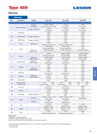
Type 459
1) Max. set pressure 69 bar / 1000 psig for Type 4593 acc. to ASME-Code Sec. VIII, Div. 1 with UV-Stamp.
The design of Type 4593 is permitted with limitations acc. to ASME-Code Sec. VIII, Div. 1, UCD-2, UCD-3.
Type 4593 shall not be used for lethal substances, irrespective of their state of aggregation.
Metal seat
Type459](https://image.slidesharecdn.com/39dd659d-0f12-40d3-8ff4-3594fb05bf13-160314115249/85/LESER-Safety-Valve-Compact-Performance-Extended-Catalog-EN-44-320.jpg)
![45
Dimensions and weights – Threaded connections [Metric units]
Height [mm]
Conventional design Balanced bellows
Size inlet thread 1/2" 3/4" 1" 11/4" 11/2" 2" 1/2" 3/4" 1" 11/4" 11/2" 2"
DIN ISO 228-1 G H max. 296 298 301 303 305 – 328 330 333 335 337 –
ISO 7-1/BS 21 R H max. 298 299 303 – 305 – 330 331 335 – 337 –
ASME B1.20.1 NPT H max. 301 301 307 308 308 309 333 333 339 340 340 341
Threaded connections
Size Outlet body 1/2" x 1" 3/4" x 1" 1" x 1" 1/2" x 1" 3/4" x 1" 1" x 1" 3/4" x 11/2" 1" x 11/2" 11/4" x 11/2" 11/2" x 11/2"
Actual Orifice diameter d0 [mm] 9 9 9 13 13 13 17.5 17.5 17.5 17.5
Actual Orifice area A0 [mm2] 63.6 63.6 63.6 133 133 133 241 241 241 241
Weight [kg] 3.1 3.1 3.1 3.1 3.1 3.1 3.9 3.9 3.9 3.9
Balanced bellows [kg] 3.9 3.9 3.9 3.9 3.9 4.7 4.7 4.7 4.7 4.7
Required installation diameter d [mm] 165 165 165 165 165 165 165 165 165 165
Inlet thread female
Size outlet body 1/2" x 1" 3/4" x 1" 1" x 1" 1/2" x 1" 3/4" x 1" 1" x 1" 3/4" x 11/2" 1" x 11/2" 11/4" x 11/2" 11/2" x 11/2"
Actual Orifice diameter d0 [mm] 9 9 9 13 13 13 17.5 17.5 17.5 17.5
Center to face / Height
DIN ISO 228-1 G
Inlet a 53 56 62 53 56 62 60 66 67 73
ASME B1.20.1 NPT
Center to face [mm] Outlet b 75 75 75 75 75 75 75 75 75 75
Height [mm] H max 283 286 292 283 286 292 287 293 294 300
Balanced bellows H max 315 318 324 315 318 324 319 325 326 332
ISO 7-1/BS 21 Rc Inlet a 53 56 64 53 56 64 60 68 – 77
Center to face [mm] Outlet b 75 75 75 75 75 75 75 75 – 75
Height [mm] H max 283 286 294 283 286 294 287 295 – 304
Balanced bellows H max 315 318 326 315 318 326 319 327 – 336
Length of screwed end c [mm]
Size inlet thread 1/2" 3/4" 1" 11/4" 11/2" 2"
DIN ISO 228-1 G 14 16 18 20 22 –
ISO 7-1/BS 21 R 19 20 23 – 25 –
ASME B1.20.1 NPT 22 22 27 28 28 29
1) Inlet thread R only up to 11/2“.
Required installation
diameter
Conventional design –
female thread
Conventional design –
male thread
Balanced bellows
d
c c
Type 459
Type459
Inlet thread male
Size outlet body 1" – 11/2" 1" – 11/2" 11/2" 2"
Actual Orifice diameter d0 [mm] 9 13 17.5 17.5
Center to face [mm]
DIN ISO 228-1 G Inlet 1/2" – 1" a 52 52 – –
Inlet 1"– 11/2" a – – 56 –
Outlet b 75 75 75 –
ISO 7-1/BS 21 R Inlet 1/2" – 1" a 49 49 – –
ASME B1.20.1 NPT Inlet 1" – 2" a1) – – 53 53
Outlet b 75 75 75 100](https://image.slidesharecdn.com/39dd659d-0f12-40d3-8ff4-3594fb05bf13-160314115249/85/LESER-Safety-Valve-Compact-Performance-Extended-Catalog-EN-45-320.jpg)
![46
Dimensions and weights – Threaded connections [US units]
Height [inch]
Conventional design Balanced bellows
Size inlet thread 1/2" 3/4" 1" 11/4" 11/2" 2" 1/2" 3/4" 1" 11/4" 11/2" 2"
DIN ISO 228-1 G H max. 1121/32 1123/32 1127/32 1115/16 12 – 1229/32 13 131/8 133/16 139/32 –
ISO 7-1/BS 21 R H max. 1123/32 1125/32 1115/16 – 12 – 13 131/32 133/16 – 139/32 –
ASME B1.20.1 NPT H max. 1127/32 1127/32 123/32 121/8 121/8 125/32 131/8 131/8 1311/32 133/8 133/8 137/16
Threaded connections
Size Outlet body 1/2" x 1" 3/4" x 1" 1" x 1" 1/2" x 1" 3/4" x 1" 1" x 1" 3/4" x 11/2" 1" x 11/2" 11/4" x 11/2" 11/2" x 11/2"
Actual Orifice diameter d0 [inch] 0.354 0.354 0.354 0.512 0.512 0.512 0.689 0.689 0.689 0.689
Actual Orifice area A0 [inch2] 0.099 0.099 0.099 0.206 0.206 0.206 0.374 0.374 0.374 0.374
Weight [lbs] 6.8 6.8 6.8 6.8 6.8 6.8 8.6 8.6 8.6 8.6
Balanced bellows [lbs] 8.6 8.6 8.6 8.6 8.6 8.6 10.4 10.4 10.4 10.4
Required installation diameter d [inch] 61/2 61/2 61/2 61/2 61/2 61/2 61/2 61/2 61/2 61/2
Inlet thread female
Size outlet body 1/2" x 1" 3/4" x 1" 1" x 1" 1/2" x 1" 3/4" x 1" 1" x 1" 3/4" x 11/2" 1" x 11/2" 11/4" x 11/2" 11/2" x 11/2"
Actual Orifice diameter d0 [inch] 0.354 0.354 0.354 0.512 0.512 0.512 0.689 0.689 0.689 0.689
Center to face / Height
DIN ISO 228-1 G
Inlet a 23/32 27/32 27/16 23/32 27/32 27/16 23/8 219/32 25/8 27/8
ASME B1.20.1 NPT
Center to face [inch] Outlet b 215/16 215/16 215/16 215/16 215/16 215/16 215/16 215/16 215/16 215/16
Height [inch] H max. 115/32 111/14 111/2 115/32 111/14 111/2 115/16 1117/32 119/16 1113/16
Balanced bellows H max. 1213/32 1217/32 123/4 1213/32 1217/32 123/4 129/16 1225/32 1227/32 131/16
ISO 7-1/BS 21 Rc Inlet a 23/32 27/32 217/32 23/32 27/32 217/32 23/8 211/16 – 31/32
Center to face [inch] Outlet b 215/16 215/16 215/16 215/16 215/16 215/16 215/16 215/16 – 215/16
Height [inch] H max. 115/32 111/14 119/16 115/32 111/14 119/16 115/16 115/8 – 1131/32
Balanced bellows H max. 1213/32 1217/32 1227/32 1213/32 1217/32 1227/32 129/16 127/8 – 137/32
Length of screwed end c [inch]
Size inlet thread 1/2" 3/4" 1" 11/4" 11/2" 2"
DIN ISO 228-1 G 9/16
5/8
23/32
25/32
7/8 –
ISO 7-1/BS 21 R 3/4
25/32
29/32 – 31/32 –
ASME B1.20.1 NPT 7/8
7/8 11/16 13/32 13/32 15/32
1) Inlet thread R only to 11/2".
Required installation
diameter
Conventional design –
female thread
Conventional design –
male thread
Balanced bellows
d
c c
Type 459
Type459
Inlet thread male
Size outlet body 1" – 11/2" 1" – 11/2" 11/2" 2"
Actual Orifice diameter d0 [mm] 0.354 0.512 0.689 0.689
Center to face [inch]
DIN ISO 228-1 G Inlet 1/2" – 1" a 21/16 21/16 – –
Inlet 1"– 11/2" a – – 27/32 –
Outlet b 215/16 215/16 215/16 –
ISO 7-1/BS 21 R Inlet 1/2" – 1" a 115/16 115/16 – –
ASME B1.20.1 NPT Inlet 1" – 2" a1) – – 23/32 23/32
Outlet b 215/16 215/16 215/16 4](https://image.slidesharecdn.com/39dd659d-0f12-40d3-8ff4-3594fb05bf13-160314115249/85/LESER-Safety-Valve-Compact-Performance-Extended-Catalog-EN-46-320.jpg)
![47
Dimensions and weights – Flanged connections [Metric units]
Flanged connections
Conventional design Balanced bellows
Actual Orifice diameter d0 [mm] 9 13 17.5 9 13 17.5
Actual Orifice area A0 [mm2] 63.6 133 241 63.6 133 241
DIN EN 1092-1 (Available flange sizes refer to page 09/07)
Flange rating PN 40 – PN 400
Center to face [mm] Inlet a 100 100 105 100 100 105
Outlet b 100 100 100 100 100 100
Height [mm] H max. 330 330 333 375 375 378
ASME B 16.5 (Available flange sizes refer to page 09/07)
Flange rating class 150 – 2500
Center to face [mm] Inlet a 100 100 105 100 100 105
Outlet b 100 100 100 100 100 100
Height [mm] H max. 330 330 333 375 375 378
Note The outlet dimension b can differ at special combinations of nominal diameter and pressure range if flanged connections are used at the inlet and outlet.
Special dimensions are possible. More information at sales@leser.com.
Weight
For the calculation of the total weight please use the Formular: WT = WN + WF (Inlet) + WF (Outlet)
Weight net [kg]
3.1 3.1 3.9 4.3 4.3 5.1
(without inlet and outlet flange) mN
Flange dimensions
DIN EN 1092-1 / Flange rating PN ASME B16.5 / Flange rating
Size 40 100 160 250 320 400 Size 150 300 600 900 1500 2500
DN 15 NPS 1/2"
Flange thickness [mm] s 18 – 22 28 28 30 14 18 18 26 26 30.2
Weight slip on flange [kg] mF 0.8 – 1.2 2.5 2.5 3.6 0.6 0.9 0.9 2.1 2.1 3
DN 20 NPS 3/4"
Flange thickness [mm] s 20 22 – – – – 15 18 18 25.4 25.4 32
Weight slip on flange [kg] mF 1.1 1.3 – – – – 0.8 1.4 1.4 2.3 2.3 3.5
DN 25 NPS 1"
Flange thickness [mm] s 22 – 26 30 36 40 17 21.5 21.5 32.5 32.5 40
Weight slip on flange [kg] mF 1.3 – 2.6 3.5 5 7.5 1 2.1 2.1 4.1 4.1 5.1
DN 40 NPS 11/2"
Flange thickness [mm] s 21 – 23 32 – – 22 24 24 32 – –
Weight slip on flange [kg] mF 2.1 – 2.9 4.3 – – 1.4 2.2 2.2 3.9 – –
Balanced bellowsConventional design
Type 459
Type459](https://image.slidesharecdn.com/39dd659d-0f12-40d3-8ff4-3594fb05bf13-160314115249/85/LESER-Safety-Valve-Compact-Performance-Extended-Catalog-EN-47-320.jpg)
![48
Dimensions and weights – Flanged connections [US units]
Flanged connection
Conventional design Balanced bellows
Actual Orifice diameter d0 [inch] 0.354 0.512 0.689 0.354 0.512 0.689
Actual Orifice area A0 [inch2] 0.099 0.206 0.374 0.099 0.206 0.374
DIN EN 1092-1
Flange rating PN 40 – PN 400
Center to face [inch] Inlet a 315/16 315/16 41/8 315/16 315/16 41/8
Outlet b 315/16 315/16 315/16 315/16 315/16 315/16
Height [H4] [inch] H max. 13 13 131/8 143/4 143/4 147/8
ASME B 16.5
Flange rating class 150 – 2500
Center to face [inch] Inlet a 315/16 315/16 41/8 315/16 315/16 41/8
Outlet b 315/16 315/16 315/16 315/16 315/16 315/16
Height [inch] H max. 13 13 131/8 143/4 143/4 147/8
Note The outlet dimension b can differ at special combinations of nominal diameter and pressure range if flanged connections are used at the inlet and outlet.
Special dimensions are possible. More information at sales@leser.com.
Weight
For the calculation of the total weight please use the Formular: WT = WN + WF (Inlet) + WF (Outlet)
Weight net [lbs]
6.8 6.8 8.6 9.5 9.5 11.3
(without inlet and outlet flange) mN
Flange dimensions
DIN EN 1092-1 / Flange rating PN ASME B16.5 / Flange rating
Size 40 100 160 250 320 400 Size 150 300 600 900 1500 2500
DN 15 NPS 1/2"
Flange thickness [inch] s 23/32 – 7/8 13/32 13/32 13/16
9/16
23/32
23/32 11/32 11/32 13/16
Weight slip on flange [lbs] mF 1.8 – 2.6 5.5 5.5 7.9 1.3 2.0 2.0 4.6 4.6 6.6
DN 20 NPS 3/4"
Flange thickness [inch] s 25/32
7/8 – – – – 19/32
23/32
23/32 1 1 11/4
Weight slip on flange [lbs] mF 2.4 2.9 – – – – 1.8 3.1 3.1 5.1 5.1 7.7
DN 25 NPS 1"
Flange thickness [inch] s 7/8 – 11/32 13/16 113/32 19/16
21/32
27/32
27/32 19/32 19/32 19/16
Weight slip on flange [lbs] mF 2.9 – 5.7 7.7 11.0 16.5 2.2 4.6 4.6 9.0 9.0 11.2
DN 40 NPS 11/2"
Flange thickness [inch] s 13/16 – 29/32 11/4 – – 7/8
15/16
15/16 11/4 – –
Weight slip on flange [lbs] mF 4.5 – 6.3 9.5 – – 3.2 4.8 4.8 8.6 – –
Balanced bellowsConventional design
Type 459
Type459](https://image.slidesharecdn.com/39dd659d-0f12-40d3-8ff4-3594fb05bf13-160314115249/85/LESER-Safety-Valve-Compact-Performance-Extended-Catalog-EN-48-320.jpg)
![49
Metric units
Actual Orifice diameter d0 [mm] 9 13 17.5
Actual Orifice Area A0 [mm2] 63.6 133 241
Body material: 1.4104 (430) Type 4593
Base / Connection size 1/2" 3/4" 1" 1/2" 3/4" 1" 3/4" 1" 11/4" 11/2" 2"
Inlet Body Pressure rating PN 400 PN 250 PN 160
Outlet body Pressure rating PN 40 PN 40 PN 40
Minimum
p [barg] S/G/L 1.5 0.2 0.2set pressure
Min. set pressure
standard bellows
p [barg] S/G/L 3 3 3
Min. set pressure5)
high press. bellows
p [barg] S/G/L 40 40 40
Maximum
p [barg] S/G/L 250 200 100set pressure
Temperature min. [°C ] -10
acc. to DIN EN max. [°C ] +300
Temperature min. [°C ] -29
acc. to ASME max. [°C ] +300
Body material: 1.4404 (316L) Type 4592
Base / Connection size 1/2" 3/4" 1" 1/2" 3/4" 1" 3/4" 1" 11/4" 11/2" 2"
Inlet Body
Pressure rating
PN 250
PN 500 (Option code L20)
PN 160
PN 250 (Option code L20)
PN 160
Outlet Body Pressure rating PN 160 PN 160 PN 160
Minimum
p [barg] S/G/L 1.5 0.2 0.2set pressure
Min. set pressure
standard bellows
p [barg] S/G/L 3 3 3
Min. set pressure5)
high press. bellows
p [barg] S/G/L 40 40 40
Maximum
p [barg] S/G/L 250 200 100
set pressure
Temperature min. [°C ] -851)
acc. to DIN EN max. [°C ] +4502)
Temperature min. [°C ] -29
acc. to ASME max. [°C ] +427
Body material: 1.4404 (316L) Type 4594
Base / Connection size 1/2" 3/4" 1" 1/2" 3/4" 1" 3/4" 1" 11/4" 11/2" 2"
Inlet Body
Pressure rating
PN 250
PN 500 (Option code L20)
PN 160
PN 250 (Option code L20)
PN 160
Outlet Body Pressure rating PN 160 PN 160 PN 160
Minimum
p [barg] S/G/L 1.5 0.2 0.2
set pressure
Min. set pressure
standard bellows
p [barg] S/G/L 3 3 3
Min. set pressure5)
high press. bellows
p [barg] S/G/L 40 40 40
Maximum
p [barg] S/G/L 250 200 100
set pressure
Temperature min. [°C ] -2733)
acc. to DIN EN max. [°C ] +4002)
Temperature min. [°C ] -196
acc. to ASME max. [°C ] +4502) 4)
Pressure/temperature ratings [Metric units]
Type 459
Type459
1) For DIN EN applications at temperatures under -10°C please proceed in accordance to AD-2000 Merkblatt W10:
• Load case II: under -10°C / 14°F to -60°C / -76°F, pmax = PN x 0.75
• Load case III: under -60°C / -76°F to -85°C / -121°F, pmax = PN x 0.25
2) Please notice: from 300°C / 572°F a bellows or suitable spring material e.g. Inconel X750 should be selected (refer to LDeS 3001.19).
3) For DIN EN applications at temperatures under -200°C please proceed in accordance to AD-2000 Merkblatt W10:
• Load case II: under -200°C / -328°F to -255°C / -427°F, pmax = PN x 0.75
• Load case III: under -255°C / -427°F to -273°C / -459°F, pmax = PN x 0.25
4) The temperature is limited by the standard inlet body. For applications up to 538°C/1000°F (temperature limit of outlet body) a suitable inlet body material and a
bellows or Inconel spring is requiered.
5) Min. set pressure high pressure bellows = Max. pressure standard bellows.
Because there is no open bonnet for this type available, please use at a temperature of 300 °C (572 °F) a stainless steel bellows or a specific high temperature
model without a bellows.](https://image.slidesharecdn.com/39dd659d-0f12-40d3-8ff4-3594fb05bf13-160314115249/85/LESER-Safety-Valve-Compact-Performance-Extended-Catalog-EN-49-320.jpg)
![50
Pressure/temperature ratings [US units]
US units
Actual Orifice diameter d0 [inch] 0.354 0.512 0.689
Actual Orifice Area A0 [inch2] 0.099 0.206 0.347
Body material: 1.4104 (430) Type 4593
Base /
Connection size 1/2" 3/4" 1" 1/2" 3/4" 1" 3/4" 1" 11/4" 11/2" 2"Inlet Body
Minimum
p [psig] S/G/L 21.8 2.9 2.9set pressure
Min. set pressure5)
standard bellows
p [psig] S/G/L 43.5 43.5 43.5
Min. set pressure
high press. bellows
p [psig] S/G/L 580 580 580
Maximum
p [psig] S/G/L 3626 2900 1450set pressure
Temperature min. [°F ] +14
acc. to DIN EN max. [°F ] +572
Temperature min. [°F ] -20
acc. to ASME max. [°F ] +572
Body material: 1.4404 (316L) Type 4592
Base /
Connection size 1/2" 3/4" 1" 1/2" 3/4" 1" 3/4" 1" 11/4" 11/2" 2"Inlet Body
Minimum
p [psig] S/G/L 21.8 2.9 2.9
set pressure
Min. set pressure5)
standard bellows
p [psig] S/G/L 43.5 43.5 43.5
Min. set pressure
high press. bellows
p [psig] S/G/L 580 580 580
Maximum
p [psig] S/G/L 3626 2900 1450
set pressure
Temperature min. [°F ] -1211)
acc. to DIN EN max. [°F ] +7522)
Temperature min. [°F ] -20
acc. to ASME max. [°F ] +8002)
Body material: 1.4404 (316L) Type 4594
Base /
Connection size 1 /2" 3/4" 1" 1/2" 3/4" 1" 3/4" 1" 11/4" 11/2" 2"Inlet Body
Minimum
p [psig] S/G/L 21.8 2.9 2.9set pressure
Min. set pressure5)
standard bellows
p [psig] S/G/L 43.5 43.5 43.5
Min. set pressure
high press. bellows
p [psig] S/G/L 580 580 580
Maximum
p [psig] S/G/L 3626 2900 1450
set pressure
Temperature min. [°F ] -3283)
acc. to DIN EN max. [°F ] +7522)
Temperature min. [°F ] -321
acc. to ASME max. [°F ] +8422) 4)
Type 459
1) For DIN EN applications at temperatures under -10°C please proceed in accordance to AD-2000 Merkblatt W10:
• Load case II: under -10°C / 14°F to -60°C / -76°F, pmax = PN x 0.75
• Load case III: under -60°C / -76°F to -85°C / -121°F, pmax = PN x 0.25
2) Please notice: from 300°C / 572°F a bellows or suitable spring material e.g. Inconel X750 should be selected (refer to LDeS 3001.19).
3) For DIN EN applications at temperatures under -200°C please proceed in accordance to AD-2000 Merkblatt W10:
• Load case II: under -200°C / -328°F to -255°C / -427°F, pmax = PN x 0.75
• Load case III: under -255°C / -427°F to -273°C / -459°F, pmax = PN x 0.25
4) The temperature is limited by the standard inlet body. For applications up to 538°C/1000°F (temperature limit of outlet body) a suitable inlet body material and a
bellows or Inconel spring is requiered.
5) Min. set pressure high pressure bellows = Max. pressure standard bellows.
Because there is no open bonnet for this type available, please use at a temperature of 300 °C (572 °F) a stainless steel bellows or a specific high temperature
model without a bellows.
Type459](https://image.slidesharecdn.com/39dd659d-0f12-40d3-8ff4-3594fb05bf13-160314115249/85/LESER-Safety-Valve-Compact-Performance-Extended-Catalog-EN-50-320.jpg)
![51
Approvals
Approvals
Actual Orifice diameter d0 [mm] 9 13 17.5
Actual Orifice area A0 [mm2] 63.6 133 241
Actual Orifice diameter d0 [inch] 0.354 0.512 0.689
Actual Orifice area A0 [inch2] 0.099 0.206 0.374
Europe Coefficient of discharge Kdr
PED / DIN EN ISO 4126-1
12/2013
Approval No. 072021409Z0022/15/D/0135
S/G 0.83 0.81 0.79
L 0.61 0.53 0.52
Germany Coefficient of discharge w
PED / AD 2000-Merkblatt A2
07/2012
Approval No. TÜV SV 909
S/G 0.83 0.81 0.79
L 0.61 0.53 0.52
United States Coefficient of discharge K
ASME Sec. VIII Div. 1
Approval No. M 37112
S/G 0.811
Approval No. M 37101
L 0.566
Canada Coefficient of discharge K
CRN
Approval No. The current approval no. can be found at www.leser.com
S/G 0.811
L 0.566
China Coefficient of discharge w
AQSIQ
Approval No. The current approval no. can be found at www.leser.com
S/G 0.83 0.81 0.79
L 0.61 0.53 0.52
Eurasian Custom Union Coefficient of discharge w
EAC
Approval No. The current approval no. can be found at www.leser.com
S/G 0.83 0.81 0.79
L 0.61 0.53 0.52
Classification societies Homepage
Bureau Veritas BV www.bureauveritas.com
The valid certification number is changed
with every reneval.
A sample certificate including the valid certification number
can be found at www.leser.com
DNV GL www.dnvgl.com
Lloyd‘s Register EMEA LREMEA www.lr.org
Registro Italiano Navale RINA www.rina.org
U.S. Coast Guard U.S.C.G www.uscg.org
Type 459
Type459](https://image.slidesharecdn.com/39dd659d-0f12-40d3-8ff4-3594fb05bf13-160314115249/85/LESER-Safety-Valve-Compact-Performance-Extended-Catalog-EN-51-320.jpg)


![55
Article numbers
Actual Orifice diameter d0 [mm] 61) 9
Actual Orifice area A0 [mm2] 28.3 63.9
Actual Orifice diameter d0 [inch] 0.236 0.354
Actual Orifice area A0 [inch2] 0.044 0.099
Body material: 14404 (316L)
Outlet body
Bonnet
1.4408
CF8M
1.4404
1.4408
H2 Art. No. 4594. 2132 2142
H4 Art. No. 4594. 2134 2144
p [barg]
S/G/L
420.01 – 850 250.01 – 420
p [psig] 6091 – 12328 3626 – 6091
Article numbers
1) The specification of the medium is necessary at liquid applications (Option Code M09).
Type 459 HDD
Metal seat
Type459HDD](https://image.slidesharecdn.com/39dd659d-0f12-40d3-8ff4-3594fb05bf13-160314115249/85/LESER-Safety-Valve-Compact-Performance-Extended-Catalog-EN-55-320.jpg)
![56
Height [mm]
Conventional design Balanced bellows
Size inlet thread 1/2" 3/4" 1" 1/2" 3/4" 1"
DIN ISO 228-1 G H max. 296 298 301 328 330 333
ISO 7-1/BS 21 R H max. 298 299 303 330 331 335
ASME B1.20.1 NPT H max. 301 301 307 333 333 339
Length of screwed end c [mm]
Size inlet thread 1/2" 3/4" 1"
DIN ISO 228-1 G 14 16 18
ISO 7-1/BS 21 R 19 20 23
ASME B1.20.1 NPT 22 22 27
Threaded connections
Size Outlet body 1/2" x 1" 3/4" x 1" 1" x 1" 1/2" x 1" 3/4" x 1" 1" x 1"
Actual Orifice diameter d0 [mm] 6 6 6 9 9 9
Actual Orifice area A0 [mm2] 28.3 28.3 28.3 63.6 63.6 63.6
Weight [kg] 3.1 3.1 3.1 3.1 3.1 3.1
Balanced bellows [kg] 3.9 3.9 3.9 3.9 3.9 3.9
Required installation diameter d [mm] 165 165 165 165 165 165
Inlet thread female
Size outlet body 1/2" x 1" 3/4" x 1" 1" x 1" 1/2" x 1" 3/4" x 1" 1" x 1"
Actual Orifice diameter d0 [mm] 6 6 6 9 9 9
Center to face / Height
DIN ISO 228-1 G
Inlet a 53 53 62*) 53 56 62
ASME B1.20.1 NPT
Center to face [mm] Outlet b 75 75 75*) 75 75 75
Height [mm] H max. 283 286 292*) 283 286 292
Balanced bellows H max. 315 318 342*) 315 318 324
ISO 7-1/BS 21 Rc Inlet a 53 56 64 53 56 64
Center to face [mm] Outlet b 75 75 75 75 75 75
Height [mm] H max. 283 286 294 283 286 294
Balanced bellows H max. 315 318 326 315 318 326
Inlet thread male
Size outlet body 1" 1"
Actual Orifice diameter d0 [mm] 6 9
Center to face [mm]
DIN ISO 228-1 G Inlet a 52 52
Outlet b 75 75
ISO 7-1/BS 21 R Inlet a 49 49
ASME B1.20.1 NPT Outlet b 75 75
*) DIN ISO 228-1 G not possible.
Type 459 HDD
Dimensions and weights – Threaded connections [Metric units]
Type459HDD
Required installation
diameter
Conventional design –
female thread
Conventional design –
male thread
Balanced bellows
d
c c](https://image.slidesharecdn.com/39dd659d-0f12-40d3-8ff4-3594fb05bf13-160314115249/85/LESER-Safety-Valve-Compact-Performance-Extended-Catalog-EN-56-320.jpg)
![57
Height [inch]
Conventional design Balanced bellows
Size inlet thread 1/2" 3/4" 1" 1/2" 3/4" 1"
DIN ISO 228-1 G H max. 1121/32 1123/32 1127/32 1229/32 13 131/8
ISO 7-1/BS 21 R H max. 1123/32 1125/32 1115/16 13 131/32 133/16
ASME B1.20.1 NPT H max. 1127/32 1127/32 123/32 131/8 131/8 1311/32
Length of screwed end c [inch]
Size inlet thread 1/2" 3/4" 1"
DIN ISO 228-1 G 9/16
5/8
23/32
ISO 7-1/BS 21 R 3/4
25/32
29/32
ASME B1.20.1 NPT 7/8
7/8 11/16
Threaded connections
Size Outlet body 1/2" x 1" 3/4" x 1" 1" x 1" 1/2" x 1" 3/4" x 1" 1" x 1"
Actual Orifice diameter d0 [inch] 0.236 0.236 0.236 0.354 0.354 0.354
Actual Orifice area A0 [inch2] 0.044 0.044 0.044 0.099 0.099 0.099
Weight [lbs] 6.8 6.8 6.8 6.8 6.8 6.8
Balanced bellows [lbs] 8.6 8.6 8.6 8.6 8.6 8.6
Required installation diameter d [inch] 61/2 61/2 61/2 61/2 61/2 61/2
Inlet thread female
Size outlet body 1/2" x 1" 3/4" x 1" 1" x 1" 1/2" x 1" 3/4" x 1" 1" x 1"
Actual Orifice diameter d0 [inch] 0.236 0.236 0.236 0.354 0.354 0.354
Center to face / Height
DIN ISO 228-1 G
Inlet a 23/32 27/32 27/16*) 23/32 27/32 27/16
ASME B1.20.1 NPT
Center to face [inch] Outlet b 215/16 215/16 215/16*) 215/16 215/16 215/16
Height [inch] H max. 115/32 111/14 111/2*) 115/32 111/14 111/2
Balanced bellows H max. 1213/32 1217/32 123/4*) 1213/32 1217/32 123/4
ISO 7-1/BS 21 Rc Inlet a 23/32 27/32 217/32 23/32 27/32 217/32
Center to face [inch] Outlet b 215/16 215/16 215/16 215/16 215/16 215/16
Height [inch] H max. 115/32 111/14 119/16 115/32 111/14 119/16
Balanced bellows H max. 1213/32 1217/32 1227/32 1213/32 1217/32 1227/32
Inlet thread male
Size outlet body 1" 1"
Actual Orifice diameter d0 [inch] 1/4
11/32
Center to face [inch]
DIN ISO 228-1 G Inlet a 21/16 21/16
Outlet b 215/16 215/16
ISO 7-1/BS 21 R Inlet a 115/16 115/16
ASME B1.20.1 NPT Outlet b 215/16 215/16
*) DIN ISO 228-1 G not possible.
Dimensions and weights – Threaded connections [US units]
Type 459 HDD
Type459HDD
Required installation
diameter
Conventional design –
female thread
Conventional design –
male thread
Balanced bellows
d
c c](https://image.slidesharecdn.com/39dd659d-0f12-40d3-8ff4-3594fb05bf13-160314115249/85/LESER-Safety-Valve-Compact-Performance-Extended-Catalog-EN-57-320.jpg)
![58
Flanged connections
Conventional design Balanced bellows
Actual Orifice diameter d0 [mm] 6 9 6 9
Actual Orifice area A0 [mm2] 28.3 63.6 28.3 63.6
DIN EN 1092-1 (Available flange sizes refer to page 09/07)
Flange rating PN 40 – PN 400
Center to face [mm] Inleta 100 100 100 100
Outlet b 100 100 100 100
Height [mm] H max. 330 330 375 375
ASME B 16.5 (Available flange sizes refer to page 09/07)
Flange rating class 150 – 2500
Center to face [mm] Inlet a 100 100 100 100
Outlet b 100 100 100 100
Height [mm] H max. 330 330 375 375
Note The outlet dimension b can differ at special combinations of nominal diameter and pressure range if flanged connections are used at the inlet and outlet.
Special dimensions are possible. More information at sales@leser.com.
Weight
For the calculation of the total weight please use the Formular: WT = WN + WF (Inlet) + WF (Outlet)
Weight net [kg]
3.1 3.1 4.3 4.3
(without inlet and outlet flange) mN
Flange dimensions
DIN EN 1092-1 / Flange rating PN DIN ISO 1092-1 / Flange rating class
Size 40 100 160 250 320 400 Size 150 300 600 900 1500 2500
DN 15 NPS 1/2"
Flange thickness [mm] s 18 – 22 28 28 30 14 18 18 26 26 30.2
Weight slip on flange [kg] mF 0.8 – 1.2 2.5 2.5 3.6 0.6 0.9 0.9 2.1 2.1 3
DN 20 NPS 3/4"
Flange thickness [mm] s 20 22 – – – – 15 18 18 25.4 25.4 32
Weight slip on flange [kg] mF 1.1 1.3 – – – – 0.8 1.4 1.4 2.3 2.3 3.5
DN 25 NPS 1"
Flange thickness [mm] s 22 – 26 30 36 40 17 21.5 21.5 32.5 32.5 40
Weight slip on flange [kg] mF 1.3 – 2.6 3.5 5 7.5 1 2.1 2.1 4.1 4.1 5.1
DN 40 NPS 11/2"
Flange thickness [mm] s 21 – 23 32 – – 22 24 24 32 – –
Weight slip on flange [kg] mF 2.1 – 2.9 4.3 – – 1.4 2.2 2.2 3.9 – –
Type 459 HDD
Dimensions and weights – Flanged connections [Metric units]
Type459HDD
Balanced bellowsConventional design](https://image.slidesharecdn.com/39dd659d-0f12-40d3-8ff4-3594fb05bf13-160314115249/85/LESER-Safety-Valve-Compact-Performance-Extended-Catalog-EN-58-320.jpg)
![59
Flanged connections
Conventional design Balanced bellows
Actual Orifice diameter d0 [inch] 0.236 0.354 0.236 0.354
Actual Orifice area A0 [inch2] 0.044 0.099 0.044 0.099
DIN EN 1092-1 (Available flange sizes refer to page 09/07)
Flange rating PN 40 – PN 400
Center to face [inch] Inlet a 315/16 315/16 315/16 315/16
Outlet b 315/16 315/16 315/16 315/16
Height [inch] H max. 13 13 143/4 143/4
ASME B 16.5 (Available flange sizes refer to page 09/07)
Flange rating class 150 – 2500
Center to face [inch] Inlet a 315/16 315/16 315/16 315/16
Outlet b 315/16 315/16 315/16 315/16
Height [inch] H max. 13 13 143/4 143/4
Note The outlet dimension b can differ at special combinations of nominal diameter and pressure range if flanged connections are used at the inlet and outlet.
Special dimensions are possible. More information at sales@leser.com.
Weight
For the calculation of the total weight please use the Formular: WT = WN + WF (Inlet) + WF (Outlet)
Weight net [lbs]
6.8 6.8 9.5 9.5
(without inlet and outlet flange) mN
Flange dimensions
DIN EN 1092-1 / Flange rating PN ASME B16.5 / Flange rating class
Size 40 100 160 250 320 400 Size 150 300 600 900 1500 2500
DN 15 NPS 1/2"
Flange thickness [mm] s 23/32 – 7/8 13/32 13/32 13/16
9/16
23/32
23/32 11/32 11/32 13/16
Weight slip on flange [kg] mF 1.8 – 2.6 5.5 5.5 7.9 1.3 2 2 4.6 4.6 6.6
DN 20 NPS 3/4"
Flange thickness [mm] s 25/32
7/8 – – – – 19/32
23/32
23/32 1 1 11/4
Weight slip on flange [kg] mF 2.4 2.9 – – – – 1.8 3.1 3.1 5.1 5.1 7.7
DN 25 NPS 1"
Flange thickness [mm] s 7/8 – 11/32 13/16 13/32 19/16
21/32
27/32
27/32 19/32 19/32 19/16
Weight slip on flange [kg] mF 2.9 – 5.7 7.7 11 16.5 2.2 4.6 4.6 9 9 11.2
DN 40 NPS 11/2"
Flange thickness [mm] s 13/16 – 29/32 11/4 – – 7/8
15/16
15/16 11/4 – –
Weight slip on flange [kg] mF 4.5 – 6.3 9.5 – – 3.2 4.8 4.8 8.6 – –
Dimensions and weights – Flanged connections [US units]
Type 459 HDD
Type459HDD
Balanced bellowsConventional design](https://image.slidesharecdn.com/39dd659d-0f12-40d3-8ff4-3594fb05bf13-160314115249/85/LESER-Safety-Valve-Compact-Performance-Extended-Catalog-EN-59-320.jpg)
![60
Metric units
Actual Orifice diameter d0 [mm] 6 9
Actual Orifice Area A0 [mm2] 28.3 63.6
Body material 1.4404 (316L) Type 4594
Base / Connection size 1/2" 3/4" 1" 1/2" 3/4" 1"
Inlet Body Pressure rating PN 700 PN 500
Outlet body Pressure rating PN 160 PN 160
Minimum
p [barg] S/G/L 420 250.01set pressure
Maximum p [barg] S/G 850
420set pressure p [barg] L –
Temperature min. [°C ] -2731) -2731)
acc. to DIN EN max. [°C ] +4002) +4002)
Temperature min. [°C ] -196 -196
acc. to ASME max. [°C ] +4503) +4503)
Pressure/temperature ratings [Metric units + US units]
US units
Actual Orifice diameter d0 [inch] 0.236 0.354
Actual Orifice Area A0 [inch2] 0.044 0.099
Body material 1.4404 (316L) Type 4594
Base /
Connection size 1/2" 3/4" 1" 1/2" 3/4" 1"Inlet Body
Minimum
p [psig] S/G/L 6091 3626set pressure
Maximum p [psig] S/G 12328
6091set pressure p [psig] L –
Temperature min. [°F ] -4591) -4591)
acc. to DIN EN max. [°F ] +7522) +7522)
Temperature min. [°F ] -321 -321
acc. to ASME max. [°F ] +8423) +8423)
Type 459 HDD
1) For DIN EN applications at temperatures under -200°C / -328°F please proceed in accordance to AD-2000 Merkblatt W10.
• Load case II: under -200°C / -328°F to -255°C / -427°F, pmax = PN x 0.75
• Load case III: under -255°C / -427°F to -273°C / -459°F, pmax = PN x 0.25
2) Please notice: from 300°C / 572°F, a bellows or suitable spring material e.g. Inconel X750 should be selected (refer to LDeS 3001.19). For the temperature range
>400°C / >752°F an outlet body material e.g. 1.4552 or 1.4581 (special casting) is required.
3) The temperature is limited by the standard inlet body. For applications up to 538°C/1000°F (temperature limit of outlet body) a suitable inlet body material and a
bellows or Inconel spring is requiered.
Type459HDD](https://image.slidesharecdn.com/39dd659d-0f12-40d3-8ff4-3594fb05bf13-160314115249/85/LESER-Safety-Valve-Compact-Performance-Extended-Catalog-EN-60-320.jpg)
![61
Approvals
Approvals
Actual Orifice diameter d0 [mm] 6 9
Actual Orifice area A0 [mm2] 28.3 63.6
Actual Orifice diameter d0 [inch] 0.236 0.354
Actual Orifice area A0 [inch2] 0.044 0.099
Europe Coefficient of discharge Kdr
PED / DIN EN ISO 4126-1
12/2013
Approval No. 072021409Z0022/15/D/0135
S/G 0.81 0.83
L 0.70 0.61
Germany Coefficient of discharge w
PED / AD 2000-Merkblatt A2
07/2012
Approval No. TÜV SV 909
S/G 0.81 0.83
L 0.70 0.61
United States Coefficient of discharge K
ASME Sec. VIII Div. 1
Approval No. M 37112
S/G 0.811
Approval No. M 37112
L 0.566
Canada Coefficient of discharge K
CRN
Approval No. The current approval no. can be found at www.leser.com
S/G 0.811
L 0.566
China Coefficient of discharge w
AQSIQ
Approval No. The current approval no. can be found at www.leser.com
S/G 0.81 0.83
L 0.70 0.61
Eurasian Custom Union Coefficient of discharge w
EAC
Approval No. The current approval no. can be found at www.leser.com
S/G 0.81 0.83
L 0.70 0.61
Classification societies Homepage
Bureau Veritas BV www.bureauveritas.com The valid certification number is changed
with every reneval.
A sample certificate including the valid certifi-
cation number
can be found at www.leser.com
DNV GL www.dnvgl.com
Lloyd‘s Register EMEA LREMEA www.lr.org
Registro Italiano Navale RINA www.rina.org
U.S. Coast Guard U.S.C.G www.uscg.org
Type 459 HDD
Type459HDD](https://image.slidesharecdn.com/39dd659d-0f12-40d3-8ff4-3594fb05bf13-160314115249/85/LESER-Safety-Valve-Compact-Performance-Extended-Catalog-EN-61-320.jpg)

![65
Article numbers
Type 462
Actual Orifice diameter d0 [mm] 9 13 17.5
Actual Orifice area A0 [mm2] 63.6 133 241
Actual Orifice diameter d0 [inch] 0.354 0.512 0.689
Actual Orifice area A0 [inch2] 0.099 0.206 0.374
O-ring material NBR “N” J302)
CR “K” J212)
EPDM “D” J222)
FKM “L” J232)
FFKM “C” J203)
Outlet body casted
Inlet body 1.4104 H2 Art. No. 4623. 2902 2912 2922
Outlet body
1.0619
WCB
H3 Art. No. 4623. 2903 2913 2923
Bonnet 0.7043 H4 Art. No. 4623. 2904 2914 2924
p [barg]
S/G/L
0.5 – 2501) 0.5 – 1801) 0.5 – 92.51)
p [psig] 7.3 – 36261) 7.3 – 26111) 7.3 – 13421)
Outlet body investment casted
Inlet body 1.4404 H2 Art. No. 4622. 3772 3782 3792
Outlet body 1.0619
WCB
H3 Art. No. 4622. 3773 3783 3793
Bonnet
1.0460
1.0619
H4 Art. No. 4622. 3774 3784 3794
p [barg]
S/G/L
0.5 – 250 0.5 – 180 0.5 – 92.5
p [psig] 7.3 – 3626 7.3 – 2611 7.3 – 1342
Outlet body investment casted
Inlet body 1.4404
H2 Art. No. 4624. 2192 2202 2212
Outlet body
1.4408
CF8M
Bonnet
1.4404
1.4408
H4 Art. No. 4624. 2194 2204 2214
p [barg]
S/G/L
0.5 – 250 0.5 – 180 0.5 – 92.5
p [psig] 7.3 – 3626 7.3 – 2611 7.3 – 1342
Type 462
Type 462 Refrigeration technology
DNE 15, 20 15, 20, 25 25
DNA 20 25 32
Actual Orifice diameter d0 [mm] 13 13 17,5
Actual Orifice area A0 [mm2] 133 133 241
Weight [kg] 3.1 3.1 3.9
O-ring material NBR “N” J30
CR “K” J21
EPDM “D” J22
Outlet body investment casted
Inlet + Outlet PN 40
Inlet body 1.4404 H2 Art. No. 4622. 3882 3982 3892
Outlet body
1.0619
WCB
Bonnet 1.0619
p [barg] D/G/F 0,5 – 40 40 40
Also all other LESER valve types can be designed for refrigeration technology.
1) Max. set pressure 69 bar / 1000 psig for Type 4623 acc. to ASME-Code Sec. VIII, Div. 1 with UV-Stamp.
The design of Type 4623 is permitted with limitations acc. to ASME-Code Sec. VIII, Div. 1, UCD-2, UCD-3.
Type 4623 shall not be used for lethal substances, irrespective of their state of aggregation.
2) d0 9 + 13: O-ring 90 Shore for set pressure > 100 bar
3) d0 9 + 13: O-ring 90 Shore for set pressure > 40 bar
Type462](https://image.slidesharecdn.com/39dd659d-0f12-40d3-8ff4-3594fb05bf13-160314115249/85/LESER-Safety-Valve-Compact-Performance-Extended-Catalog-EN-65-320.jpg)
![66
Dimensions and weights – Threaded connections [Metric units]
Height [mm]
Conventional design Balanced bellows
Size inlet thread 1/2" 3/4" 1" 11/4" 11/2" 2" 1/2" 3/4" 1" 11/4" 11/2" 2"
DIN ISO 228-1 G H max. 296 298 301 303 305 – 328 330 333 335 337 –
ISO 7-1/BS 21 R H max. 298 299 303 – 305 – 330 331 335 – 337 –
ASME B1.20.1 NPT H max. 301 301 307 307 308 309 333 333 339 340 340 341
Threaded connections
Size Outlet body 1/2" x 1" 3/4" x 1" 1" x 1" 1/2" x 1" 3/4" x 1" 1" x 1" 3/4" x 11/2" 1" x 11/2" 11/4" x 11/2"11/2" x 11/2"
Actual Orifice diameter d0 [mm] 9 9 9 13 13 13 17.5 17.5 17.5 17.5
Actual Orifice area A0 [mm2] 63.6 63.6 63.6 133 133 133 241 241 241 241
Weight [kg] 3.1 3.1 3.1 3.1 3.1 3.1 3.9 3.9 3.9 3.9
Balanced bellows [kg] 3.9 3.9 3.9 3.9 3.9 3.9 4.7 4.7 4.7 4.7
Required installation diameter d [mm] 165 165 165 165 165 165 165 165 165 165
Inlet thread female
Size Outlet body 1/2" x 1" 3/4" x 1" 1" x 1" 1/2" x 1" 3/4" x 1" 1" x 1" 3/4" x 11/2" 1" x 11/2" 11/4" x 11/2"11/2" x 11/2"
Actual Orifice diameter d0 [mm] 9 9 9 13 13 13 17.5 17.5 17.5 17.5
Center to face / Height
DIN ISO 228-1 G
Inlet a 53 56 62 53 56 62 60 66 67 73
ASME B1.20.1 NPT
Center to face [mm] Outlet b 75 75 75 75 75 75 75 75 75 75
Height [mm] H max. 283 286 292 283 286 292 287 293 294 300
Balanced bellows H max. 315 318 324 315 318 324 319 325 326 332
ISO 7-1/BS 21 Rc Inlet a 53 56 64 53 56 64 60 68 – 77
Center to face [mm] Outlet b 75 75 75 75 75 75 75 75 – 75
Height [mm] H max. 283 286 294 283 286 294 287 295 – 304
Balanced bellows H max. 315 318 326 315 318 326 319 327 – 336
Length of screwed end c [mm]
Size inlet thread 1/2" 3/" 1" 11/4" 11/2" 2"
DIN ISO 228-1 G 14 16 18 20 22 24
ISO 7-1/BS 21 R 19 20 23 25 25 –
ASME B1.20.1 NPT 22 22 27 28 28 29
1) Inlet thread R only up to 11/2".
Required installation
diameter
Conventional design –
Female thread
Conventional design –
Male thread
Balanced bellows
d
c c
Type 462
Type462
Inlet thread male
Size outlet body 1" – 11/2" 1" – 11/2" 11/2" 2"
Actual Orifice diameter d0 [mm] 9 13 17.5 17.5
Center to face [mm]
DIN ISO 228-1 G Inlet 1/2" – 1" a 52 52 – –
Inlet 1"– 11/2" a – – 56 –
Outlet b 75 75 75 –
ISO 7-1/BS 21 R Inlet 1/2" – 1" a 49 49 – –
ASME B1.20.1 NPT Inlet 1" – 2" a1) – – 53 53
Outlet b 75 75 75 100](https://image.slidesharecdn.com/39dd659d-0f12-40d3-8ff4-3594fb05bf13-160314115249/85/LESER-Safety-Valve-Compact-Performance-Extended-Catalog-EN-66-320.jpg)
![67
Dimensions and weights – Threaded connections [US units]
Height [inch]
Conventional design Balanced bellows
Size inlet thread 1/2" 3/4" 1" 11/4" 11/2" 2" 1/2" 3/4" 1" 11/4" 11/2" 2"
DIN ISO 228-1 G H max. 1121/32 1123/32 1127/32 1115/16 12 – 1229/32 13 131/8 133/16 139/32 –
ISO 7-1/BS 21 R H max. 1123/32 1125/32 1115/16 – 12 – 13 131/32 133/16 – 139/32 –
ASME B1.20.1 NPT H max. 1127/32 1127/32 123/32 121/8 121/8 125/32 131/8 131/8 1311/32 133/8 133/8 137/16
Threaded connections
Size Outlet body 1/2" x 1" 3/4" x 1" 1" x 1" 1/2" x 1" 3/4" x 1" 1" x 1" 3/4" x 11/2" 1" x 11/2" 11/4" x 11/2"11/2" x 11/2"
Actual Orifice diameter d0 [inch] 0.354 0.354 0.354 0.512 0.512 0.512 0.689 0.689 0.689 0.689
Actual Orifice area A0 [inch2] 0.099 0.099 0.099 0.206 0.206 0.206 0.374 0.374 0.374 0.374
Weight [lbs] 6.8 6.8 6.8 6.8 6.8 6.8 8.6 8.6 8.6 8.6
Balanced bellows [lbs] 8.6 8.6 8.6 8.6 8.6 8.6 10.4 10.4 10.4 10.4
Required installation diameter d [inch] 61/2 61/2 61/2 61/2 61/2 61/2 61/2 61/2 61/2 61/2
Inlet thread female
Size Outlet body 1/2" x 1" 3/4" x 1" 1" x 1" 1/2" x 1" 3/4" x 1" 1" x 1" 3/4" x 11/2" 1" x 11/2" 11/4" x 11/2"11/2" x 11/2"
Actual Orifice diameter d0 [inch] 0.354 0.354 0.354 0.512 0.512 0.512 0.689 0.689 0.689 0.689
Center to face / Height
DIN ISO 228-1 G
Inlet a 23/32 27/32 27/16 23/32 27/32 27/16 23/8 219/32 25/8 27/8
ASME B1.20.1 NPT
Center to face [inch] Outlet b 215/16 215/16 215/16 215/16 215/16 215/16 215/16 215/16 215/16 215/16
Height [inch] H max. 115/32 111/14 111/2 115/32 111/4 111/2 115/16 1117/32 119/16 1113/16
Balanced bellows H max. 1213/32 1217/32 123/4 1213/32 1217/32 123/4 129/16 1225/32 1227/32 131/16
ISO 7-1/BS 21 Rc Inlet a 23/32 27/32 217/32 23/32 27/32 217/32 23/8 211/16 – 31/32
Center to face [inch] Outlet b 215/16 215/16 215/16 215/16 215/16 215/16 215/16 215/16 – 215/16
Height [inch] H max. 115/32 111/14 119/16 115/32 111/14 119/16 115/16 115/8 – 1131/32
Balanced bellows H max. 1213/32 1217/32 1227/32 1213/32 1217/32 1227/32 129/16 127/8 – 137/32
Length of screwed end c [inch]
Size inlet thread 1/2" 3/" 1" 11/4" 11/2" 2"
DIN ISO 228-1 G 9/16
5/8
23/32
25/32
7/8
15/16
ISO 7-1/BS 21 R 3/4
25/32
29/32
31/32
31/32 –
ASME B1.20.1 NPT 7/8
7/8 11/16 13/32 13/32 15/32
1) Inlet thread R only up to 11/2".
Required installation
diameter
Conventional design –
Female thread
Conventional design –
Male thread
Balanced bellows
d
c c
Type 462
Type462
Inlet thread male
Size outlet body 1" – 11/2" 1" – 11/2" 11/2" 2"
Actual Orifice diameter d0 [mm] 0.354 0.512 0.689 0.689
Center to face [inch]
DIN ISO 228-1 G Inlet 1/2" – 1" a 21/16 21/16 – –
Inlet 1"– 11/2" a – – 27/32 –
Outlet b 215/16 215/16 215/16 –
ISO 7-1/BS 21 R Inlet 1/2" – 1" a 115/16 115/16 – –
ASME B1.20.1 NPT Inlet 1" – 2" a1) – – 23/32 23/32
Outlet b 215/16 215/16 215/16 4](https://image.slidesharecdn.com/39dd659d-0f12-40d3-8ff4-3594fb05bf13-160314115249/85/LESER-Safety-Valve-Compact-Performance-Extended-Catalog-EN-67-320.jpg)
![68
Dimensions and weights – Flanged connections [Metric units]
Flanged connections
Conventional design Balanced bellows
Actual Orifice diameter d0 [mm] 9 13 17.5 9 13 17.5
Actual Orifice area A0 [mm2] 63.6 133 241 63.6 133 241
DIN EN 1092-1
Flange rating PN 40 – 400
Center to face [mm] Inlet a 100 100 105 100 100 105
Outlet b 100 100 100 100 100 100
Height [mm] H max. 330 330 333 375 375 378
ASME B 16.5
Flange rating class 150 – 2500
Center to face [mm] Inlet a 100 100 105 100 100 105
Outlet b 100 100 100 100 100 100
Height [mm] H max. 330 330 333 375 375 378
Note The outlet dimension b can differ at special combinations of nominal diameter and pressure range if flanged connections are used at the inlet and outlet.
Special dimensions are possible. More information at sales@leser.com.
Weight
For the calculation of the total weight please use the Formular: WT = WN + WF (Inlet) + WF (Outlet)
Weight net [kg]
3.1 3.1 3.5 4.3 4.3 4.7
(without inlet and outlet flange) mN
Flange dimensions
DIN EN 1092-1 / Flange rating PN ASME B16.5 / Flange rating class
Size 40 100 160 250 320 400 Size 150 300 600 900 1500 2500
DN 15 NPS 1/2"
Flange thickness [mm] s 18 – 22 28 28 30 14 18 18 26 26 30.2
Weight slip on flange [kg] mF 0.8 – 1.2 2.5 2.5 3.6 0.6 0.9 0.9 2.1 2.1 3
DN 20 NPS 3/4"
Flange thickness [mm] s 20 22 – – – – 15 18 18 25.4 25.4 32
Weight slip on flange [kg] mF 1.1 1.3 – – – – 0.8 1.4 1.4 2.3 2.3 3.5
DN 25 NPS 1"
Flange thickness [mm] s 22 – 26 30 36 40 17 21.5 21.5 32.5 32.5 40
Weight slip on flange [kg] mF 1.3 – 2.6 3.5 5 7.5 1 2.1 2.1 4.1 4.1 5.1
DN 40 NPS 11/2"
Flange thickness [mm] s 21 – 23 32 – – 22 24 24 32 – –
Weight slip on flange [kg] mF 2.1 – 2.9 4.3 – – 1.4 2.2 2.2 3.9 – –
Balanced bellowsConventional design
Type 462
Type462](https://image.slidesharecdn.com/39dd659d-0f12-40d3-8ff4-3594fb05bf13-160314115249/85/LESER-Safety-Valve-Compact-Performance-Extended-Catalog-EN-68-320.jpg)
![69
Dimensions and weights – Flanged connections [US units]
Flanged connections
Conventional design Balanced bellows
Actual Orifice diameter d0 [inch] 0.354 0.512 0.689 0.354 0.512 0.689
Actual Orifice area A0 [inch2] 0.099 0.206 0.374 0.099 0.206 0.374
DIN EN 1092-1
Flange rating PN 40 – 400
Center to face [inch] Inlet a 315/16 315/16 41/8 315/16 315/16 41/8
Outlet b 315/16 315/16 315/16 315/16 315/16 315/16
Height [inch] H max. 13 13 131/8 143/4 143/4 147/8
ASME B 16.5
Flange rating class 150 – 2500
Center to face [inch] Inlet a 315/16 315/16 41/8 315/16 315/16 41/8
Outlet b 315/16 315/16 315/16 315/16 315/16 315/16
Height [inch] H max. 13 13 131/8 143/4 143/4 147/8
Note The outlet dimension b can differ at special combinations of nominal diameter and pressure range if flanged connections are used at the inlet and outlet.
Special dimensions are possible. More information at sales@leser.com.
Weight
For the calculation of the total weight please use the Formular: WT = WN + WF (Inlet) + WF (Outlet)
Weight net [lbs]
6.8 6.8 7.7 9.5 9.5 10.4
(without inlet and outlet flange) mN
Flange dimensions
DIN EN 1092-1 / Flange rating PN ASME B16.5 / Flange rating class
Size 40 100 160 250 320 400 Size 150 300 600 900 1500 2500
DN 15 NPS 1/2"
Flange thickness [mm] s 23/32 – 7/8 13/32 13/32 13/16
9/16
23/32
23/32 11/32 11/32 13/16
Weight slip on flange [lbs] mF 1.8 – 2.6 5.5 5.5 7.9 1.3 2.0 2.0 4.6 4.6 6.6
DN 20 NPS 3/4"
Flange thickness [mm] s 25/32
7/8 – – – – 19/32
23/32
23/32 1 1 11/4
Weight slip on flange [lbs] mF 2.4 2.9 – – – – 1.8 3.1 3.1 5.1 5.1 7.7
DN 25 NPS 1"
Flange thickness [mm] s 7/8 – 11/32 13/16 13/32 19/16
21/32
27/32
27/32 19/32 19/32 19/16
Weight slip on flange [lbs] mF 2.9 – 5.7 7.7 11.0 16.5 2.2 4.6 4.6 9.0 9.0 11.2
DN 40 NPS 11/2"
Flange thickness [mm] s 13/16 – 29/32 11/4 – – 7/8
15/16
15/16 11/4 – –
Weight slip on flange [lbs] mF 4.5 – 6.3 9.5 – – 3.2 4.8 4.8 8.6 – –
Balanced bellowsConventional design
Type 462
Type462](https://image.slidesharecdn.com/39dd659d-0f12-40d3-8ff4-3594fb05bf13-160314115249/85/LESER-Safety-Valve-Compact-Performance-Extended-Catalog-EN-69-320.jpg)
![70
Metric units
Actual Orifice diameter d0 [mm] 9 13 17.5
Actual Orifice Area A0 [mm2] 63.6 133 241
Body material: 1.4104 (430F) Type 4623
Base / Connection size 1/2" 3/4" 1" 1/2" 3/4" 1" 3/4" 1" 11/4" 11/2" 2"
Inlet Body Pressure rating PN 400 PN 250 PN 160
Outlet body Pressure rating PN 40 PN 40 PN 40
Minimum
p [barg] S/G/L 0.5 0.5 0.5set pressure
Min. set pressure
standard bellows
p [barg] S/G/L 3 3 3
Min. set pressure1)
high press. bellows
p [barg] S/G/L 40 40 40
Maximum
p [barg] S/G/L 250 180 92.5set pressure
Temperature min. [°C ] -102)
acc. to DIN EN3)
max. [°C ] +150
Temperature min. [°C ] -29
acc. to ASME3)
max. [°C ] +150
Body material: 1.4404 (316L) Type 4622
Base / Connection size 1/2" 3/4" 1" 1/2" 3/4" 1" 3/4" 1" 11/4" 11/2" 2"
Inlet Body Pressure rating PN 250 PN 160 PN 160
Outlet Body Pressure rating PN 160 PN 160 PN 160
Minimum
p [barg] S/G/L 0.5 0.5 0.5
set pressure
Min. set pressure
standard bellows
p [barg] S/G/L 3 3 3
Min. set pressure1)
high press. bellows
p [barg] S/G/L 40 40 40
Maximum
p [barg] S/G/L 250 180 92.5
set pressure
Temperature min. [°C ] -45
acc. to DIN EN3)
max. [°C ] +150
Temperature min. [°C ] -29
acc. to ASME3)
max. [°C ] +150
Body material: 1.4404 (316L) Type 4624
Base / Connection size 1/2" 3/4" 1" 1/2" 3/4" 1" 3/4" 1" 11/4" 11/2" 2"
Inlet Body Pressure rating PN 250 PN 160 PN 160
Outlet Body Pressure rating PN 160 PN 160 PN 160
Minimum
p [barg] S/G/L 0.5 0.5 0.5
set pressure
Min. set pressure
standard bellows
p [barg] S/G/L 3 3 3
Min. set pressure1)
high press. bellows
p [barg] S/G/L 40 40 40
Maximum
p [barg] S/G/L 250 180 92.5
set pressure
Temperature min. [°C ] -45
acc. to DIN EN3)
max. [°C ] +150
Temperature min. [°C ] -45
acc. to ASME3)
max. [°C ] +150
Pressure/temperature ratings [Metric units]
1) Min. set pressure high pressure bellows = Max. pressure standard bellows.
2) For DIN EN applications at temperatures under -10°C please proceed according to AD 2000-Merkblatt W10.
3) The temperature is limited by the soft seal material. The stated values are valid for EPDM.
Type 462
Type462](https://image.slidesharecdn.com/39dd659d-0f12-40d3-8ff4-3594fb05bf13-160314115249/85/LESER-Safety-Valve-Compact-Performance-Extended-Catalog-EN-70-320.jpg)
![71
Pressure/temperature ratings [US units]
US units
Actual Orifice diameter d0 [inch] 0.354 0.512 0.689
Actual Orifice Area A0 [inch2] 0.099 0.206 0.374
Body material: 1.4104 (430F) Type 4623
Base /
Inlet body Connection size 1/2" 3/4" 1" 1/2" 3/4" 1" 3/4" 1" 11/4" 11/2" 2"
Minimum
p [psig] S/G/L 7.3 7.3 7.3set pressure
Min. set pressure
standard bellows
p [psig] S/G/L 43.5 43.5 43.5
Min. set pressure1)
high press. bellows
p [psig] S/G/L 580 580 580
Maximum
p [psig] S/G/L 3626 2611 1342set pressure
Temperature min. [°F ] +142)
acc. to DIN EN3)
max. [°F ] +302
Temperature min. [°F ] -20
acc. to ASME3)
max. [°F ] +302
Body material: 1.4404 (316L) Type 4622
Base /
Inlet body Connection size 1/2" 3/4" 1" 1/2" 3/4" 1" 3/4" 1" 11/4" 11/2" 2"
Minimum
p [psig] S/G/L 7.3 7.3 7.3
set pressure
Min. set pressure
standard bellows
p [psig] S/G/L 43.5 43.5 43.5
Min. set pressure1)
high press. bellows
p [psig] S/G/L 580 580 580
Maximum
p [psig] S/G/L 3626 2611 1342
set pressure
Temperature min. [°F ] -49
acc. to DIN EN3)
max. [°F ] +302
Temperature min. [°F ] -20
acc. to ASME3)
max. [°F ] +302
Body material: 1.4404 (316L) Type 4624
Base /
Inlet body Connection size 1/2" 3/4" 1" 1/2" 3/4" 1" 3/4" 1" 11/4" 11/2" 2"
Minimum
p [psig] S/G/L 7.3 7.3 7.3
set pressure
Min. set pressure
standard bellows
p [psig] S/G/L 43.5 43.5 43.5
Min. set pressure1)
high press. bellows
p [psig] S/G/L 580 580 580
Maximum
p [psig] S/G/L 3626 2611 1342
set pressure
Temperature min. [°F ] -49
acc. to DIN EN3)
max. [°F ] +302
Temperature min. [°F ] -49
acc. to ASME3)
max. [°F ] +302
1) Min. set pressure high pressure bellows = Max. pressure standard bellows.
2) For DIN EN applications at temperatures under -10°C please proceed according to AD 2000-Merkblatt W10.
3) The temperature is limited by the soft seal material. The stated values are valid for EPDM.
Type 462
Type462](https://image.slidesharecdn.com/39dd659d-0f12-40d3-8ff4-3594fb05bf13-160314115249/85/LESER-Safety-Valve-Compact-Performance-Extended-Catalog-EN-71-320.jpg)
![72
Approvals
Approvals
Actual Orifice diameter d0 [mm] 9 13 17.5
Actual Orifice area A0 [mm2] 63.6 133 241
Actual Orifice diameter d0 [inch] 0.354 0.512 0.689
Actual Orifice area A0 [inch2] 0.099 0.206 0.374
Europe Coefficient of discharge Kdr
PED / DIN EN ISO 4126-1
12/2013
Approval No. 072021409Z0022/15/D/0135
S/G 0.83 0.81 0.79
L 0.61 0.61 0.52
Germany Coefficient of discharge w
PED / AD 2000-Merkblatt A2
07/2012
Approval No. TÜV SV 909
S/G 0.83 0.81 0.79
L 0.61 0.61 0.52
United States Coefficient of discharge K
ASME Sec. VIII Div. 1
Approval No. M 37112
S/G 0.811
Approval No. M 37101
L 0.566
Canada Coefficient of discharge K
CRN
Approval No. The current approval no. can be found at www.leser.com
S/G 0.811
L 0.566
China Coefficient of discharge w
AQSIQ
Approval No. The current approval no. can be found at www.leser.com
S/G 0.83 0.81 0.79
L 0.61 0.61 0.52
Eurasian Custom Union Coefficient of discharge w
EAC
Approval No. The current approval no. can be found at www.leser.com
S/G 0.83 0.81 0.79
L 0.61 0.61 0.52
Classification societies Homepage
Bureau Veritas BV www.bureauveritas.com
The valid certification number is changed
with every reneval.
A sample certificate including the valid certification number
can be found at www.leser.com
DNV GL DNV www.dnvgl.com
Lloyd‘s Register EMEA LREMEA www.lr.org
Registro Italiano Navale RINA www.rina.org
U.S. Coast Guard U.S.C.G www.uscg.org
Type 462
Type462](https://image.slidesharecdn.com/39dd659d-0f12-40d3-8ff4-3594fb05bf13-160314115249/85/LESER-Safety-Valve-Compact-Performance-Extended-Catalog-EN-72-320.jpg)

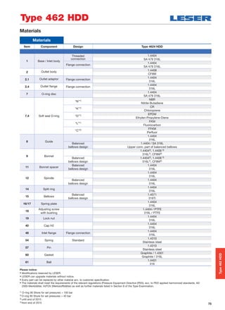
![76
Article numbers
Article numbers
Actual Orifice diameter d0
[mm]
9
Actual Orifice area A0
[mm2]
63,9
Actual Orifice diameter d0 [inch] 0.354
Actual Orifice area A0 [inch2] 0.099
O-ring material NBR “N” J301)
CR “K” J211)
EPDM “D” J221)
FKM “L” J231)
FFKM “C” J202)
Body material: 1.4404 (316L)
Outlet body
Bonnet
1.4408
CF8M
1.4404
1.4408
H2 Art. No. 4624. 2252
H4 Art. No. 4624. 2254
p [barg]
S/G/L
250.01 – 350
p [psig] 3626 – 5076
Type 462 HDD
O-ring disc
Type462HDD
1) O-ring 90 Shore for set pressures > 100 bar
2) O-ring 90 Shore for set pressures > 40 bar](https://image.slidesharecdn.com/39dd659d-0f12-40d3-8ff4-3594fb05bf13-160314115249/85/LESER-Safety-Valve-Compact-Performance-Extended-Catalog-EN-76-320.jpg)
![77
Dimensions and weights – Threaded connections [Metric units]
Threaded connections
Size Outlet body 1/2" x 1" 3/4" x 1" 1" x 1"
Actual Orifice diameter d0 [mm] 9 9 9
Actual Orifice area A0 [mm2] 63.6 63.6 63.6
Weight [kg] 3.1 3.1 3.1
Balanced bellows [kg] 3.9 3.9 3.9
Required installation diameter d [mm] 165 165 165
Inlet thread female
Size Outlet body 1/2" x 1" 3/4" x 1" 1" x 1"
Actual Orifice diameter d0 [mm] 9 9 9
Center to face / Height
DIN ISO 228-1 G
Inlet a 53 56 62
ASME B1.20.1 NPT
Center to face [mm] Outlet b 75 75 75
Height [mm] H max. 283 286 292
Balanced bellows H max. 315 318 324
ISO 7-1/BS 21 Rc Inlet a 53 56 64
Center to face [mm] Outlet b 75 75 75
Height [mm] H max. 283 286 294
Balanced bellows H max. 315 318 326
Inlet thread male
Size outlet body 1"
Actual Orifice diameter d0 [mm] 9
Center to face [mm]
DIN ISO 228-1 G
Inlet a 52
Outlet b 75
ISO 7-1/BS 21 R
Inlet a 49
ASME B1.20.1 NPT
Outlet b 75
Height [mm]
Size inlet thread
Conventional design Balanced bellows
1/2" 3/4" 1" 1/2" 3/4" 1"
DIN ISO 228-1 G H max. 296 298 301 328 330 333
ISO 7-1/BS 21 R H max. 298 299 303 330 331 335
ASME B1.20.1 NPT H max. 301 301 307 333 333 339
Length of screwed end c [mm]
Size inlet thread 1/2" 3/4" 1"
DIN ISO 228-1 G 14 16 18
ISO 7-1/BS 21 R 19 20 23
ASME B1.20.1 NPT 22 22 27
Type 462 HDD
Type462HDD
Required installation
diameter
Conventional design –
female thread
Conventional design –
male thread
Balanced bellows
d
c c](https://image.slidesharecdn.com/39dd659d-0f12-40d3-8ff4-3594fb05bf13-160314115249/85/LESER-Safety-Valve-Compact-Performance-Extended-Catalog-EN-77-320.jpg)
![78
Threaded connections
Size Outlet body 1/2" x 1" 3/4" x 1" 1" x 1"
Actual Orifice diameter d0 [inch] 0.354 0.354 0.354
Actual Orifice area A0 [inch2] 0.099 0.099 0.099
Weight [lbs] 6.8 6.8 6.8
Balanced bellows [lbs] 8.6 8.6 8.6
Required installation diameter d [inch] 61/2 61/2 61/2
Inlet thread female
Size Outlet body 1/2" x 1" 3/4" x 1" 1" x 1"
Actual Orifice diameter d0 [inch] 0.354 0.354 0.354
Center to face / Height
DIN ISO 228-1 G
Inlet a 23/32 27/32 27/16
ASME B1.20.1 NPT
Center to face [inch] Outlet b 215/16 215/16 215/16
Height [inch] H max. 115/32 111/14 111/2
Balanced bellows H max. 1213/32 1217/32 123/4
ISO 7-1/BS 21 Rc Inlet a 23/32 27/32 217/32
Center to face [inch] Outlet b 215/16 215/16 215/16
Height [inch] H max. 115/32 111/14 119/16
Balanced bellows H max. 1213/32 1217/32 1227/32
Inlet thread male
Size outlet body 1"
Actual Orifice diameter d0 [inch] 0.354
Center to face [inch]
DIN ISO 228-1 G
Inlet a 21/16
Outlet b 215/16
ISO 7-1/BS 21 R
Inlet a 115/16
ASME B1.20.1 NPT
Outlet b 215/16
Height [inch]
Size inlet thread
Conventional design Balanced bellows
3/8" 1/2" 3/8" 1/2" 3/8" 1/2"
DIN ISO 228-1 G H max. 1121/32 1123/32 1127/32 1229/32 13 131/8
ISO 7-1/BS 21 R H max. 1123/32 1125/32 1115/16 13 131/32 133/16
ASME B1.20.1 NPT H max. 1127/32 1127/32 123/32 131/8 131/8 1311/32
Length of screwed end “c” [inch]
Size inlet thread 1/2" 3/4" 1"
DIN ISO 228-1 G 9/16
5/8
23/32
ISO 7-1/BS 21 R 3/4
25/32
29/32
ASME B1.20.1 NPT 7/8
7/8
11/16
Type 462 HDD
Dimensions and weights – Threaded connections [US units]
Type462HDD
Required installation
diameter
Conventional design –
female thread
Conventional design –
male thread
Balanced bellows
d
c c](https://image.slidesharecdn.com/39dd659d-0f12-40d3-8ff4-3594fb05bf13-160314115249/85/LESER-Safety-Valve-Compact-Performance-Extended-Catalog-EN-78-320.jpg)
![79
Flanged connections
Conventional design Balanced bellows
Actual Orifice diameter d0 [mm] 9 9
Actual Orifice area A0 [mm2] 63.6 63.6
DIN EN 1092-1
Flange rating PN 40 – 400
Center to face [mm] Inlet a 100 100
Outlet b 100 100
Height [mm] H max. 330 375
ASME B 16.5
Flange rating class 150 – 2500
Center to face [mm] Inlet a 100 100
Outlet b 100 100
Height [mm] H max. 330 375
Note The outlet dimension b can differ at special combinations of nominal diameter and pressure range if flanged connections are used at the inlet and outlet.
Special dimensions are possible. More information at sales@leser.com.
Weight
For the calculation of the total weight please use the Formular: WT = WN + WF (Inlet) + WF (Outlet)
Weight net [kg]
3.1 4.3
(without inlet and outlet flange) mN
Flange dimensions
DIN EN 1092-1 / Flange rating PN ASME B16.5 / Flange rating class
Size 40 100 160 250 320 400 Size 150 300 600 900 1500 2500
DN 15 NPS 1/2"
Flange thickness [mm] s 18 – 22 28 28 30 14 18 18 26 26 30.2
Weight slip on flange [kg] mF 0.8 – 1.2 2.5 2.5 3.6 0.6 0.9 0.9 2.1 2.1 3
DN 20 NPS 3/4"
Flange thickness [mm] s 20 22 – – – – 15 18 18 25.4 25.4 32
Weight slip on flange [kg] mF 1.1 1.3 – – – – 0.8 1.4 1.4 2.3 2.3 3.5
DN 25 NPS 1"
Flange thickness [mm] s 22 – 26 30 36 40 17 21.5 21.5 32.5 32.5 40
Flange thickness [kg] mF 1.3 – 2.6 3.5 5 7.5 1 2.1 2.1 4.1 4.1 5.1
DN 40 NPS 11/2"
Flanschblattdicke [mm] s 21 – 23 32 – – 22 24 24 32 – –
Weight slip on flange [kg] mF 2.1 – 2.9 4.3 – – 1.4 2.2 2.2 3.9 – –
Type 462 HDD
Dimensions and weights – Flanged connections [Metric units]
Type462HDD
Balanced bellowsConventional design](https://image.slidesharecdn.com/39dd659d-0f12-40d3-8ff4-3594fb05bf13-160314115249/85/LESER-Safety-Valve-Compact-Performance-Extended-Catalog-EN-79-320.jpg)
![80
Dimensions and weights – Flanged connections [US units]
Flanged connections
Conventional design Balanced bellows
Actual Orifice diameter d0 [inch] 0.354 0.354
Actual Orifice area A0 [inch2] 0.099 0.099
DIN EN 1092-1
Flange rating PN 40 – 400
Center to face [inch] Inlet a 315/16 315/16
Outlet b 315/16 315/16
Height [inch] H max. 13 143/4
ASME B 16.5
Flange rating class 150 – 2500
Center to face [inch] Inlet a 315/16 315/16
Outlet b 315/16 315/16
Height [inch] H max. 13 143/4
Note The outlet dimension b can differ at special combinations of nominal diameter and pressure range if flanged connections are used at the inlet and outlet.
Special dimensions are possible. More information at sales@leser.com.
Weight
For the calculation of the total weight please use the Formular: WT = WN + WF (Inlet) + WF (Outlet)
Weight net [lbs]
6.8 9.5
(without inlet and outlet flange) mN
Flange dimensions
DIN EN 1092-1 / Flange rating PN ASME B16.5 / Flange rating class
Size 40 100 160 250 320 400 Size 150 300 600 900 1500 2500
DN 15 NPS 1/2"
Flange thickness [inch] s 23/32 – 7/8 13/32 13/32 13/16
9/16
23/32
23/32 11/32 11/32 13/16
Weight slip on flange [lbs] mF 1.8 – 2.6 5.5 5.5 7.9 1.3 2.0 2.0 4.6 4.6 6.6
DN 20 NPS 3/4"
Flange thickness [inch] s 25/32
7/8 – – – – 19/32
23/32
23/32 1 1 11/4
Weight slip on flange [lbs] mF 2.4 2.9 – – – – 1.8 3.1 3.1 5.1 5.1 7.7
DN 25 NPS 1"
Flange thickness [inch] s 7/8 – 11/32 13/16 13/32 19/16
21/32
27/32
27/32 19/32 19/32 19/16
Flange thickness [lbs] mF 2.9 – 5.7 7.7 11.0 16.5 2.2 4.6 4.6 9.0 9.0 11.2
DN 40 NPS 11/2"
Flanschblattdicke [inch] s 13/16 – 29/32 11/4 – – 7/8
15/16
15/16 11/4 – –
Weight slip on flange [lbs] mF 4.5 – 6.3 9.5 – – 3.2 4.8 4.8 8.6 – –
Type 462 HDD
Type462HDD
Balanced bellowsConventional design](https://image.slidesharecdn.com/39dd659d-0f12-40d3-8ff4-3594fb05bf13-160314115249/85/LESER-Safety-Valve-Compact-Performance-Extended-Catalog-EN-80-320.jpg)
![81
Pressure/temperature ratings [Metric units + US units]
Metric units
Actual Orifice diameter d0 [mm] 9
Actual Orifice Area A0 [mm2] 63.6
Body material 1.4404 (316L) Type 4624
Base / Connection size 1/2" 3/4" 1"
Inlet Body Pressure rating PN 500
Outlet body Pressure rating PN 160
Minimum
p [barg] S/G/L 250.01set pressure
Maximum
p [barg] S/G/L 350set pressure
Temperature min. [°C ] -45
acc. to DIN EN1)
max. [°C ] +150
Temperature min. [°C ] -45
acc. to ASME1)
max. [°C ] +150
US units
Actual Orifice diameter d0 [inch] 0.354
Actual Orifice Area A0 [inch2] 0.099
Body material 1.4404 (316L) Type 4624
Base /
Connection size 1/2" 3/4" 1"Inlet Body
Minimum
p [psig] S/G/L 3626set pressure
Maximum
p [psig] S/G/L 5076set pressure
Temperature min. [°F ] -49
acc. to DIN EN1)
max. [°F ] +302
Temperature min. [°F ] -49
acc. to ASME1)
max. [°F ] +302
1) The temperature is limited by soft seal material. The stated values are valid for EPDM.
Type 462 HDD
Type462HDD](https://image.slidesharecdn.com/39dd659d-0f12-40d3-8ff4-3594fb05bf13-160314115249/85/LESER-Safety-Valve-Compact-Performance-Extended-Catalog-EN-81-320.jpg)
![82
Approvals
Approvals
Actual Orifice diameter d0 [mm] 9
Actual Orifice area A0 [mm2] 63.6
Actual Orifice diameter d0 [inch] 0.354
Actual Orifice area A0 [inch2] 0.099
Europe Coefficient of discharge Kdr
PED / DIN EN ISO 4126-1
12/2013
Approval No. 072021409Z0022/15/D/0135
S/G 0.83
L 0.61
Germany Coefficient of discharge w
PED / AD 2000-Merkblatt A2
07/2012
Approval No. TÜV SV 909
S/G 0.83
L 0.61
United States Coefficient of discharge K
ASME Sec. VIII Div. 1
Approval No. M 37112
S/G 0.811
Approval No. M 37101
L 0.566
Canada Coefficient of discharge K
CRN
Approval No. The current approval no. can be found at www.leser.com
S/G 0.811
L 0.566
China Coefficient of discharge w
AQSIQ
Approval No. The current approval no. can be found at www.leser.com
S/G 0.83
L 0.61
Eurasian Custom Union Coefficient of discharge w
EAC
Approval No. The current approval no. can be found at www.leser.com
S/G 0.83
L 0.61
Classification societies Homepage
Bureau Veritas BV www.bureauveritas.com
The valid certification number is changed
with every reneval.
A sample certificate including the valid certification number
can be found at www.leser.com
DNV GL www.dnvgl.com
Lloyd‘s Register EMEA LREMEA www.lr.org
Registro Italiano Navale RINA www.rina.org
U.S. Coast Guard U.S.C.G www.uscg.org
Type 462 HDD
Type462HDD](https://image.slidesharecdn.com/39dd659d-0f12-40d3-8ff4-3594fb05bf13-160314115249/85/LESER-Safety-Valve-Compact-Performance-Extended-Catalog-EN-82-320.jpg)
![84
Available connections
Threaded connections
Actual Orifice diameter d0 [mm] 6 9 / 13 17.5
Actual Orifice area A0 [mm2] 28.3 63.9 / 133 241
Actual Orifice diameter d0 [inch] 0.236 0.345 / 0.512 0.689
Actual Orifice area A0 [inch2] 0.044 0.099 / 0.206 0.374
Inlet Outlet Inlet Outlet Inlet Outlet
Male thread DIN ISO 228-1
G
1/2" V545) – V541) – – –
3/4 " V555) – V55 – – –
1" V565) V56 V68 V56 –
11/4" – – – V83 –
11/2" – V69 – V69 V57 V69
Female thread DIN ISO 228-1
G
1/2" V505) – V50 – – –
3/4 " V515) – V51 – V51 –
1" – V66 V522) V66 V52 –
11/4" – V81 – V81 V84 –
11/2" – V67 – V67 V53 V67
Male thread ISO 7-1/BS 21
R/BSPT
1/2" V303) 5) – V306) – – –
3/4 " V315) – V31 – – –
1" V325) V32 V42 V32 –
11/2" – V43 – V43 V33 V43
Female thread ISO 7-1/BS 21
Rc/BSPT
1/2" V385) – V38 – – –
3/4 " V395) – V39 – V39 –
1" V405) V40 V36 V40 –
11/2" – V37 – V37 V41 V37
Male thread ANSI/ASME B1.20.1
NPT
1/2" V615) – V614) – – –
3/4 " V625) – V62 – – –
1" V635) V63 V73 V63 –
11/4" – – – V85 –
11/2" – V74 – V74 V64 V74
2" – – – – V86 –
Female thread ANSI/ASME B1.20.1
NPT
1/2" V585) – V58 – – –
3/4 " V595) – V59 – V59 –
1" V605) V71 V60 V71 V60 –
11/4" – V80 – V80 V87 –
11/2" – V72 – V72 V75 V72
2" – – – – – V88
Flanged and threaded connections can be combined.
Threads according to other standards are available. Please specify in writing (diameter, pressure rating, standard).
1) Only for d0 9 mm
2) d0 9 mm: up to PN 420
3) Only as special design
4) d0 13 mm: up to 125 bar and 455 °C
5) max. PN 700: For higher set pressures a special inlet body is required (see LDeS 3001.19)
6) V30 d0 9 mm
Series 459
Series459](https://image.slidesharecdn.com/39dd659d-0f12-40d3-8ff4-3594fb05bf13-160314115249/85/LESER-Safety-Valve-Compact-Performance-Extended-Catalog-EN-84-320.jpg)
![85
Available connections
Series 459
1) Caution! Only connecting dimensions correspond to PN 250,
outlet body and bonnet are designed for PN 160.
ANSI/ASME B 16.5
NPS CL Inlet Outlet Inlet Outlet Inlet Outlet Inlet Outlet
1/2"
150 V01 – V01 – V01 – – –
300 V02 – V02 – V02 – – –
600 V02 – V02 – V02 – – –
900 V03 – V03 – V03 – – –
1500 V03 – V03 – V03 – – –
2500 V04 – V04 – V04 – – –
3/4"
150 V05 – V05 – V05 – V05 –
300 V06 – V06 – V06 – V06 –
600 V06 – V06 – V06 – V06 –
900 V07 – V07 – V07 – V07 –
1500 V07 – V07 – V07 – V07 –
2500 V08 – V08 – V08 – V08 –
1"
150 V09 – V09 V18 V09 V18 V09 –
300 V10 V19 V10 V19 V10 V19 V10 –
600 V10 V19 V10 V19 V10 V19 V10 –
900 V11 – V11 – V11 – V11 –
1500 V11 – V11 – V11 – V11 –
2500 V12 – V12 – V12 – V12 –
11/2"
150 – – – V21 – V21 – V21
300 – – – V22 – V22 – V22
600 – – – V22 – V22 – V22
Flanged connections
Nominal diameter
Pressure
rating
d0 6 mm d0 9 mm d0 13 mm d0 17.5 mm
DIN EN 1092-1
Option code Option code Option code Option code
DN PN Inlet Outlet Inlet Outlet Inlet Outlet Inlet Outlet
15
40 I21 – I21 – I21 – – –
160 I22 – I22 – I22 – – –
250 I23 – I23 – I23 – – –
320 I24 – I24 – I24 – – –
400 I25 – I25 – I25 – – –
20
40 I26 – I26 – I26 – I26 –
160 I27 – I27 – I27 – I27 –
25
40 I31 I46 I31 I46 I31 I46 I31 –
160 I32 I47 I32 I47 I32 I47 I32 –
250 I33 I482) I33 I481) I33 I481) I33 –
320 I34 – I34 – I34 – I34 –
400 I35 – I35 – I35 – I35 –
40
40 – – – I49 – I49 – I49
160 – – – I50 – I50 – I50
250 – – – I511) – I511) – I511)
Flanged and threaded connections can be combined. Flanges according to other standards,
e.g. JIS are available. Please specify in writing (diameter, pressure rating and standard).
Type 462
Refrigeration technology
Flange facings DIN EN 1092 – groove, face D
Nominal diameter Center to face
[mm]
d0 13 mm d0 13 mm d0 17.5 mm
DIN EN 1092-1
DN a b Option code Option code Option code
Inlet Outlet Inlet Outlet Inlet Outlet Inlet Outlet Inlet Outlet
15 20 90 80 I1C I1J – – – –
20 20 90 80 I1D I1J – – – –
15 25 100 100 – – I1A I1H – –
15 25 95 95 – – I1F I1L – –
20 25 90 80 – – I1D I1K – –
20 25 95 95 – – I1G I51 – –
25 25 100 100 – – I1B I1H – –
25 25 90 80 – – I1E I1K – –
25 32 100 100 – – – – I1B I1M
Series459](https://image.slidesharecdn.com/39dd659d-0f12-40d3-8ff4-3594fb05bf13-160314115249/85/LESER-Safety-Valve-Compact-Performance-Extended-Catalog-EN-85-320.jpg)
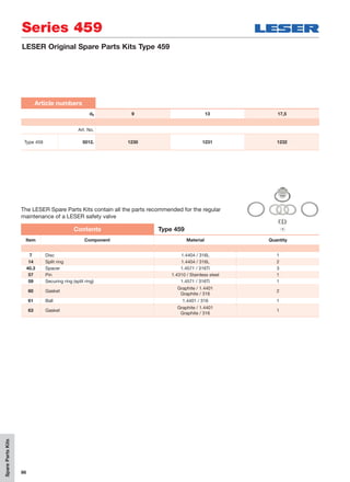
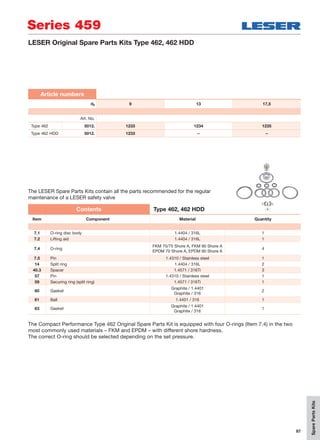


![90
Type 437
Spare parts
Spareparts
Type437
Spare parts
Actual Orifice diameter d0 [mm] 6 10
Actual Orifice area A0 [mm2] 28.3 78.5
Actual Orifice diameter d0 [inch] 0.236 0.394
Actual Orifice area A0 [inch2] 0.044 0.122
Body (Item 1): Male thread Material-No. / Art. No.
Connection Size 3/8" 1/2" 3/4" 1" 3/8" 1/2" 3/4" 1"
DIN ISO 228-1 G 1.4104 – – – – 136.5239.9000 136.4439.9000 136.4539.9000 136.5839.9000
316L – – – – 136.5249.9000 136.4449.9000 136.4549.9000 136.4849.9000
316L stellited 136.5169.9000 136.4369.9000 136.5569.9000 136.6769.9000 – – – –
R 316L – – – – – 136.4449.9220 136.4549.9220 136.5849.9220
316L stellited – 136.4369.9220 136.5569.9220 136.6769.9220 – – – –
ASME B1.20.1 NPT 316L – – – – – 136.4449.9204 136.4549.9204 136.5849.9204
316L stellited – 136.4369.9204 136.5569.9204 136.6769.9204 – – – –
Body (Item 1): Female thread Material-No. / Art. No.
Connection Size 3/8" 1/2" 3/4" 1" 3/8" 1/2" 3/4" 1"
DIN ISO 228-1 G 316L – – – – – 136.4449.9210 136.4549.9210 136.5849.9210
316L stellited – 136.4369.9210 136.5569.9210 136.6769.9210 – – – –
ISO 7-1/BS 21 Rc 316L – – – – – 136.4449.9222 136.4549.9222 136.5849.9222
316L stellited – 136.4369.9222 136.5569.9222 136.6769.9222 – 136.4449.9222 136.4549.9222 136.5869.9222
ASME B1.20.1 NPT 316L – – – – – 136.4449.9211 136.4549.9211 136.5849.9211
316L stellited – 136.4369.9211 136.5569.9211 136.6769.9211 – – – –
Body (Item 1): Flange design Material-No. / Art. No.
DN 15 / PN 40 – 400 316L – 136.6349.9208
NPS 1/2" CL150 316L – 136.4449.9202
CL300 – 2500 316L 136.4369.9208 136.6349.9208
DN 20 / PN 40 – 160 316L 136.5569.9208 136.4549.9208
NPS 3/4" CL150 – 2500 316L 136.5569.9208 136.4549.9208
DN 25 / PN 40 – 400 316L 136.6769.9208 136.4449.9208
NPS 1" CL150 – 2500 316L 136.6769.9208 136.4449.9208
Disc (Item 7): Metal to metal Material-No. / Art. No.
Disc 1.4122 420 RM – 205.3339.9000
1.4404 316L – 205.3349.9000
316L stellited 205.3169.9000 –
Disc with sealing plate (Item 7) Material-No. / Art. No.
Disc PTFE “A” 200.9249.9005 200.8449.9005
1.4404 PCTFE “G” 200.9249.9006 200.8449.9006
SP “T” 200.9249.9007 200.8449.9007
Sealing plate (Item 7.3) Material-No. / Art. No.
Sealing PTFE “A” 236.3259.0000 236.2859.0000
plate PCTFE “G” 236.3269.0000 236.2869.0000
SP “T” 236.3279.0000 236.2879.0000
Pin (Item 57) Material-No. / Art. No.
Pin 1.4310 480.2405.0000 480.2405.0000
Ball (Item 61) Material-No. / Art. No.
Ball Ball Ø [mm] 6 6
1.4401 510.0104.0000 510.0104.0000](https://image.slidesharecdn.com/39dd659d-0f12-40d3-8ff4-3594fb05bf13-160314115249/85/LESER-Safety-Valve-Compact-Performance-Extended-Catalog-EN-90-320.jpg)
![91
Spareparts
Type438
Spare parts
Type 438
Spare parts
Actual Orifice diameter d0 [mm] 10
Actual Orifice area A0 [mm2] 78.5
Actual Orifice diameter d0 [inch] 0.394
Actual Orifice area A0 [inch2] 0.122
Body (Item 1): Male thread Material-No. / Art. No.
Connection Size 3/8" 1/2" 3/4" 1"
DIN ISO 228-1 G 1.4104 136.5339.9000 136.4939.9000 136.5439.9000 136.6839.9000
316L 136.5349.9000 136.4949.9000 136.5449.9000 136.6849.9000
ISO 7-1/BS 21 R 316L – 136.4949.9220 136.5449.9220 136.6849.9220
ASME B1.20.1 NPT 316L – 136.4949.9204 136.5449.9204 136.6849.9204
Body (Item 1): Female thread Material-No. / Art. No.
Connection Size 3/8" 1/2" 3/4" 1"
DIN ISO 228-1 G 316L – 136.4949.9210 136.5449.9210 136.6849.9210
ISO 7-1/BS 21 Rc 316L – 136.4949.9222 136.5449.9222 136.6849.9222
ASME B1.20.1 NPT 316L – 136.4949.9211 136.5449.9211 136.6849.9211
Body (Item 1): Flange design Material-No. / Art. No.
DN 15 / PN 40 – 400 316L 136.4949.9208
NPS 1/2" CL150 316L 136.4949.9202
CL300 – 2500 316L 136.4949.9208
DN 20 / PN 40 – 160 316L 136.5449.9208
NPS 3/4" CL150 – 2500 316L 136.5449.9208
DN 25 / PN 40 – 400 316L 136.6449.9208
NPS 1" CL150 316L 136.6849.9202
CL150 – 2500 316L 136.6449.9208
Disc with O-ring (Item 7) Material-No. / Art. No.
Type 438 Conventional design
Type 438 Long version ≤ 120 bar
Type 438 Long version > 120 bar
Disc NBR “N” 200.8349.9781 200.9949.9083
CR “K” 200.8349.9751 200.9949.9053
EPDM “D” 200.8349.9741 200.9949.9043
FKM “L” 200.8349.9771 200.9949.9073
Type 438 Conventional design ≤ 40 bar
Type 438 Long version ≤ 40 bar
Type 438 Conventional design > 40 bar
Type 438 Long version > 40 bar
FFKM “C” 200.8349.9791 200.9949.9093
O-ring (Item 7.4) Material-No. / Art. No.
Type 438 Conventional design
Type 438 Long version ≤ 120 bar
Type 438 Long Version > 120 bar
O-ring NBR “N” 502.0107.2681 (70 Shore A) 502.0107.2683 (90 Shore A)
CR “K” 502.0107.2651 (70 Shore A) 502.0107.2653 (90 Shore A)
EPDM “D” 502.0107.2641 (70 Shore A) 502.0107.2643 (90 Shore A)
FKM “L” 502.0107.2671 (70/75 Shore A) 502.0107.2673 (90 Shore A)
Type 438 Conventional design ≤ 40 bar
Type 438 Long version ≤ 40 bar
Type 438 Conventional design > 40 bar
Type 438 Long version > 40 bar
FFKM “C” 502.0107.2691 (75 Shore A) 502.0107.2693 (90 Shore A)](https://image.slidesharecdn.com/39dd659d-0f12-40d3-8ff4-3594fb05bf13-160314115249/85/LESER-Safety-Valve-Compact-Performance-Extended-Catalog-EN-91-320.jpg)
![92
Type 439
Spare parts
Spareparts
Type439
Spare parts
Actual Orifice diameter d0 [mm] 10
Actual Orifice area A0 [mm2] 78.5
Actual Orifice diameter d0 [inch] 0.394
Actual Orifice area A0 [inch2] 0.122
Body (Item 1): Male thread Material-No. / Art. No.
Connection Size 3/8" 1/2" 3/4" 1"
DIN ISO 228-1 G 1.4104 136.5339.9000 136.4939.9000 136.5439.9000 136.6839.9000
316L 136.5349.9000 136.4949.9000 136.5449.9000 136.6849.9000
ISO 7-1/BS 21 R 316L – 136.4949.9220 136.5449.9220 136.6849.9220
ASME B1.20.1 NPT 316L – 136.4949.9204 136.5449.9204 136.6849.9204
Body (Item 1): Female thread Material-No. / Art. No.
Connection Size 3/8" 1/2" 3/4" 1"
DIN ISO 228-1 G 316L – 136.4949.9210 136.5449.9210 136.6849.9210
ISO 7-1/BS 21 R 316L – 136.4949.9222 136.5449.9222 136.6849.9222
ASME B1.20.1 NPT 316L – 136.4949.9211 136.5449.9211 136.6849.9211
Body (Item 1): Flange design Material-No. / Art. No.
DN 15 / PN 40 – 400 316L 136.4949.9208
NPS 1/2" CL150 316L 136.4949.9202
CL300 – 2500 316L 136.4949.9208
DN 20 / PN 40 – 160 316L 123.5449.9208
NPS 3/4" CL150 – 2500 316L 123.5449.9208
DN 25 / PN 40 – 400 316L 136.6449.9208
NPS 1" CL150 316L 136.6849.9202
CL300 – 2500 316L 136.6449.9208
Vulcanized soft seal disc (Item 7) Material-No. / Art. No.
Disc NBR “N” 200.9049.9081
CR “K” 200.9049.9051
EPDM “D” 200.9049.9041
FKM “L” 200.9049.9071
FFKM “C” 200.9049.9091
Disc (Item 7.1 ): With vulcanized soft seal Material-No. / Art. No.
Soft seal NBR “N” 212.5249.9081
CR “K” 212.5249.9051
EPDM “D” 212.5249.9041
FKM “L” 212.5249.9071
FFKM “C” 212.5249.9091
Pin (Item 57) Material-No. / Art. No.
Pin 1.4310 480.0305.0000
Ball (Item 61) Material-No. / Art. No.
Ball Ball Ø [mm] 6
1.4401 510.0104.0000](https://image.slidesharecdn.com/39dd659d-0f12-40d3-8ff4-3594fb05bf13-160314115249/85/LESER-Safety-Valve-Compact-Performance-Extended-Catalog-EN-92-320.jpg)
![93
Capacities
Type437
Type 437
Capacities – Steam
US Units ASME Section VIII [lb/h]
Act. Orifice dia. d0 [inch] 0.236 0.394
Act. Orifice area A0 [inch2] 0.044 0.122
LEOS/G*)
[inch2] 0.021 0.057
Set pressure [psig] Capacities [lb/h]
15 94
20 108
30 137
40 168
50 200
60 232
70 263
80 295
90 326
100 358
120 421
140 484
160 547
180 611
200 674
220 737
240 800
260 863
280 926
300 990
320 1053
340 1116
360 1179
380 1242
400 1306
420 1369
440 1432
460 1495
480 1558
500 1621
600 1937
700 2253
800 2569
900 2885
1000 3201
1100 3516
1200 3832
1300 4148
1400 4458
1500 4803
2000 6641
2500 8788
Nosaturetedsteamapplicationinsetpressurerange
Metric Units AD 2000-Merkblatt A2 [kg/h]
Act. Orifice dia. d0 [mm] 6 10
Act. Orifice area A0 [mm2] 28.3 78.5
LEOS/G*)
[inch2] 0.021 0.057
Set pressure [bar] Capacities [kg/h]
0.1 12
0.2 17
0.5 29
1 43
2 70
3 94
4 118
5 141
6 164
7 186
8 209
9 232
10 255
12 301
14 346
16 392
18 437
20 483
22 528
24 573
26 619
28 666
30 712
32 758
34 803
36 849
38 896
40 943
42 990
44 1038
46 1085
48 1133
50 1181
60 1421
70 1670
80 1921
90 2185
100 2451
110 2735
120 3032
130 3345
140 3688
150 4044
160 4445
170 4880
180 5401
Nosaturetedsteamapplicationinsetpressurerange
Capacities for saturated steam according to AD 2000-Merkblatt A2,
based on set pressure plus 10 % overpressure.Capacities at 1 bar
(14.5 psig) and below are based on 0.1 bar (1.45 psig) overpressure
Capacities for saturated steam according to ASME Section VIII (UV),
based on set pressure plus 10% overpressure. Capacities at 30 psig
(2.07 bar) and below are based on 3 psig (0.207 bar) overpressure.](https://image.slidesharecdn.com/39dd659d-0f12-40d3-8ff4-3594fb05bf13-160314115249/85/LESER-Safety-Valve-Compact-Performance-Extended-Catalog-EN-93-320.jpg)
![94
Type 437
Capacities
Type437
Metric Units AD 2000-Merkblatt A2 [mn3/h]
Act. Orifice dia. d0 [mm] 6 10
Act. Orifice area A0 [mm2] 28.3 78.5
LEOS/G*) [inch2] 0.021 0.057
Set pressure [bar] Capacities [mn
3/h]
0.1 14
0.2 19
0.5 34
1 51
2 84
3 115
4 145
5 174
6 204
7 233
8 262
9 292
10 321
12 380
14 439
16 498
18 556
20 615
22 674
24 733
26 792
28 851
30 909
32 968
34 1027
36 1086
38 1145
40 1204
42 1262
44 1321
46 1380
48 1439
50 1498
60 1792
70 2086
80 2380
90 2674
100 2969
110 3263
120 3557
130 3851
140 4145
150 4439
160 4734
170 5028
180 5322
190 2911
200 3064
210 3216
220 3369
230 3521
240 3674
250 3826
260 3979
270 4131
280 4284
290 4436
300 4589
310 4741
320 4894
330 5046
340 5199
350 5351
360 5504
370 5656
380 5809
US Units ASME Section VIII [S.C.F.M.]
Act. Orifice dia. d0 [mm] 0.236 0.394
Act. Orifice area A0 [mm2] 0.044 0.122
LEOS/G*) [inch2] 0.021 0.057
Set pressure [psig] Capacities [S.C.F.M.]
15 33
20 39
30 49
40 60
50 71
60 83
70 94
80 105
90 117
100 128
120 150
140 173
160 195
180 218
200 241
220 263
240 286
260 308
280 331
300 353
320 376
340 398
360 421
380 443
400 466
420 489
440 511
460 534
480 556
500 479
600 692
700 804
800 917
900 973
1000 1143
1100 1255
1200 1368
1300 1481
1400 1594
1500 1706
2000 2270
2500 2834
3000 1225
3500 1429
4000 1632
4500 1835
5000 2039
5500 2242
Capacities for air according to AD 2000-Merkblatt A2, based on set
pressure plus 10 % overpressure at 0 °C and 1013 mbar. Capacities
at 1 bar (14.5 psig) and below are based on 0.1 bar (1.45 psig) over-
pressure.
Capacities for air according to ASME Section VIII (UV), based on
set pressure plus 10% overpressure at 60 °F (16 °C). Capacities at
30 psig (2.07 bar) and below are based on 3 psig (0.207 bar) over-
pressure.
Capacities – Air](https://image.slidesharecdn.com/39dd659d-0f12-40d3-8ff4-3594fb05bf13-160314115249/85/LESER-Safety-Valve-Compact-Performance-Extended-Catalog-EN-94-320.jpg)
![95
Capacities
Type437
Type 437
Capacities for water according to AD 2000-Merkblatt A2, based on set
pressure plus 10 % overpressure at 20 °C (68 °F). Capacities at 1 bar
(14.5 psig) and below are based on 0.1 bar (1.45 psig) overpressure.
Capacities for water according to ASME Section VIII (UV), based on
set pressure plus 10 % overpressure at 70 °F (21 °C). Capacities at 30
psig (2.07 bar) and below are based on 3 psig (0.207 bar) overpressure.
US Units ASME Section VIII [US-G.P.M.]
Act. Orifice dia. d0 [inch] 0.236 0.394
Act. Orifice area A0 [inch2] 0.044 0.122
LEOL*)
[inch2] 0.021 0.062
Set pressure [psig] Capacities [US-G.P.M.]
15 6.54
20 7.39
30 8.86
40 10.2
50 11.4
60 12.5
70 13.5
80 14.5
90 15.3
100 16.2
120 17.7
140 19.1
160 20.5
180 21.7
200 22.9
220 24
240 25
260 26.1
280 27.1
300 28
320 28.9
340 29.8
360 30.7
380 31.5
400 32.3
420 33.1
440 33.9
460 34.7
480 35.4
500 36.2
600 39.6
700 42.8
800 45.7
900 48.5
1000 51.5
1100 53.6
1200 56
1300 58.3
1400 60.5
1500 62.6
2000 72.3
2500 80.8
Metric Units AD 2000-Merkblatt A2 [103
kg/h]
Act. Orifice dia. d0 [mm] 6 10
Act. Orifice area A0 [mm2] 28.3 78.5
LEOL*)
[inch2] 0.021 0.062
Set pressure [bar] Capacities [103kg/h]
0.1 0.63
0.2 0.77
0.5 1.08
1 1.5
2 2.1
3 2.5
4 2.9
5 3.3
6 3.6
7 3.9
8 4.1
9 4.4
10 4.6
12 5.1
14 5.5
16 5.9
18 6.2
20 6.6
22 6.9
24 7.2
26 7.5
28 7.8
30 8
32 8.3
34 8.6
36 8.8
38 9
40 9.3
42 9.5
44 9.7
46 9.9
48 10.2
50 10.4
60 11.4
70 12.3
80 13.1
90 13.9
100 14.7
110 15.4
120 16.1
130 16.7
140 17.4
150 18
160 18.5
170 19.1
180 19.7
NoTÜVapproval,useableforthermalexpansion
NoTÜVapproval,useableforthermalexpansion
Capacities – Water](https://image.slidesharecdn.com/39dd659d-0f12-40d3-8ff4-3594fb05bf13-160314115249/85/LESER-Safety-Valve-Compact-Performance-Extended-Catalog-EN-95-320.jpg)
![96
Type 437
Capacities
Type437
Determination of coefficent of discharge
in case of lift restriction or back pressure
0.7
0.6
0.8
0.5
0.3
0.4
0.835
0.8 0.90.50.4
0.1
0.3
0
0.6 0.7
0.2
0
1.1
1.0
0.9
0.8
0.7
0.6
0.5
0.3
0.4
0.2
0.1
d0 10 "S/G"
d0 6 "S/G"
Kdr = αw = f (pa0/p0) and Kb = f (pa0/p0)
CoefficientofdischargeKdr/αw
BackpressurecorrectionfactorKb
Ratio of back pressure / set pressure pa0 / p0
A lift restriction ist not applicable
because the actual design and
the certified lift are
≤ 1.5 mm / 1/16 inch.
Kdr =w = f (h/d0)
Diagram for evaluation of ratio of lift / flow diameter (h/d0)
in reference to the coefficient of discharge (Kdr /w)
Diagram for evaluation of ratio of the coefficient of discharge (Kdr/w)
in reference to the ratio of back pressure / set pressure (pa0/p0)
h = Lift [mm]
d0 = Flow diameter [mm] of selected safety
valve, refer to table article numbers
h/d0 = Ratio of lift / flow diameter
pa0 = Back pressure [bara]
p0 = Set pressure [bara]
pa0 / p0 = Ratio of back pressure / set pressure
Kdr = Coefficient of discharge
acc. to DIN EN ISO 4126-1
w = Coefficient of discharge
acc. to AD 2000-Merkblatt A2
Kb = Back pressure correction factor
acc. to API 520 topic 3.3](https://image.slidesharecdn.com/39dd659d-0f12-40d3-8ff4-3594fb05bf13-160314115249/85/LESER-Safety-Valve-Compact-Performance-Extended-Catalog-EN-96-320.jpg)
![97
Capacities
Type438
Type 438
Set pressure Capacities
Steam Air Water
saturated 60°F and
14.5 psig
70°F
[psig] [lb/h] [S.C.F.M.] [US-G.P.M.]
10
20
30
40
50
60 205 73 12.1
70 233 83 13.1
80 261 93 14
90 289 103 14.8
100 317 113 15.6
120 373 133 17.1
140 153 18.5
160 173 19.8
180 193 21
200 213 22.1
220 233 23.2
240 253 24.2
260 273 25.2
280 293 26.2
300 313 27.1
320 333 28
340 353 28.8
360 373 29.7
380 393 30.5
400 413 31.3
420 433 32
440 453 32.8
460 473 33.5
480 493 34.3
500 513 35
600 613 38.3
700 713 41.4
800 813 44.2
900 913 46.9
1000 1013 49.4
1100 1113 51.9
1200 1213 54.2
1300 1313 56.4
1400 1413 58.5
1500 1513 60.5
1600 1613 62.5
1700 1713 64.5
1800 1813 66.3
1900 1912 68.1
2000 2012 69.9
2500 2512 78.2
2650 2662 80.5
Set pressure Capacities
Steam Air Water
saturated 0°C and
1013 mbar
20°C
[bar] [kg/h] [mn
3/h] [103kg/h]
0.5
1
2
3
4
5 113 139 3.09
6 131 163 3.39
7 149 186 3.66
8 168 210 3.91
9 186 233 4.15
10 204 257 4.37
12 304 4.79
14 351 5.17
16 398 5.53
18 445 5.87
20 492 6.18
22 539 6.49
24 586 6.77
26 633 7.05
28 681 7.32
30 728 7.57
32 775 7.82
34 822 8.06
36 869 8.3
38 916 8.52
40 963 8.74
42 1010 8.96
44 1057 9.17
46 1104 9.38
48 1151 9.58
50 1198 9.78
60 1434 10.7
70 1669 11.6
80 1904 12.4
90 2140 13.1
100 2375 13.8
110 2610 14.5
120 2846 15.1
130 3081 15.8
140 3316 16.4
150 3552 16.9
160 3787 17.5
170 4022 18
180 4257 18.5
Capacities
Metric Units AD 2000-Merkblatt A2
Actual Orifice diameter d0 [mm] 10
Actual Orifice area A0 [mm2] 78.5
LEO*)
[inch2] S/G = 0.051 L = 0.06
Capacities according to AD 2000-Merkblatt A2, based on set pressure
plus 10% overpressure. Capacities at 1 bar (14.5 psig) and below are
based on 0.1 bar (1,45 psig) overpressure.
US Units ASME Section VIII
Actual Orifice diameter d0 [inch] 0.394
Actual Orifice area A0 [inch2] 0.122
LEO*)
[inch2] S/G = 0.051 L = 0.06
Capacities according to ASME Section VIII (UV), based on set pressure
plus 10% overpressure. Capacities at 30 psig (2.07 bar) and below are
based on 3 psig (0.207 bar) overpressure.
Please select Type 439 Please select Type 439](https://image.slidesharecdn.com/39dd659d-0f12-40d3-8ff4-3594fb05bf13-160314115249/85/LESER-Safety-Valve-Compact-Performance-Extended-Catalog-EN-97-320.jpg)
![98
Type 438
Capacities
Type438
A lift restriction ist not applicable
because the actual design and
the certified lift are
≤ 1.5 mm / 1/16 inch.
Kdr = w = f (h/d0)
Determination of coefficent of discharge
in case of lift restriction or back pressure
0.35
0.40
0.45
0.25
0.30
0.20
0.909
0.9 1.00.4 0.50.3
0.05
0.10
0.15
0.2
0.00
0.6 0.7 0.8
1.00
1.10
0.90
0.80
0.70
0.60
0.50
0.30
0.40
0.20
0.10
0,00
d0 10 "S/G"
Kdr = αw = f (pa0/p0) and Kb = f (pa0/p0)
CoefficientofdischargeKdr/αw
BackpressurecorrectionfactorKb
Ratio of back pressure / set pressure pa0 / p0
h = Lift [mm]
d0 = Flow diameter [mm] of selected safety
valve, refer to table article numbers
h/d0 = Ratio of lift / flow diameter
pa0 = Back pressure [bara]
p0 = Set pressure [bara]
pa0 /p0 = Ratio of back pressure / set pressure
Kdr = Coefficient of discharge
acc. to DIN EN ISO 4126-1
w = Coefficient of discharge
acc. to AD 2000-Merkblatt A2
Kb = Back pressure correction factor
acc. to API 520 topic 3.3
Diagram for evaluation of ratio of lift / flow diameter (h/d0)
in reference to the coefficient of discharge (Kdr /w)
Diagram for evaluation of ratio of the coefficient of discharge (Kdr /w)
in reference to the ratio of back pressure / set pressure (pa0/p0)](https://image.slidesharecdn.com/39dd659d-0f12-40d3-8ff4-3594fb05bf13-160314115249/85/LESER-Safety-Valve-Compact-Performance-Extended-Catalog-EN-98-320.jpg)
![99
Capacities
Type439
Type 439
Metric Units AD 2000-Merkblatt A2
Actual Orifice diameter d0 [mm] 10
Actual Orifice area A0 [mm2] 78.5
LEO*)
[inch2] S/G = 0.051 L = 0.06
Capacities
Set pressure Capacities
Steam Air Water
saturated 0°C and
1013 mbar
20°C
[bar] [kg/h] [mn
3/h] [103kg/h]
0.1 15 18 0.66
0.2 19 22 0.81
0.3 23 26 0.93
0.4 26 30 1.05
0.5 29 34 1.14
0.6 32 37 1.24
0.7 33 40 1.32
0.8 36 43 1.40
0.9 38 45 1.48
1.0 41 49 1.55
1.1 43 51 1.63
1.2 45 54 1.70
1.3 47 56 1.77
1.4 50 60 1.83
1.5 52 63 1.90
1.6 54 65 1.96
1.7 56 68 2.02
1.8 58 70 2.08
1.9 60 73 2.14
2.0 63 76 2.19
2.1 65 78 2.25
2.2 68 83 2.30
2.3 70 85 2.35
2.4 72 88 2.40
2.5 74 90 2.45
2.6 76 93 2.50
2.7 79 96 2.55
2.8 81 98 2.59
2.9 83 101 2.64
3 85 104 2.69
4 106 130 3.10
5 127 157 3.47
6 148 183 3.80
7 168 210 4.10
8 189 236 4.38
9 209 263 4.65
10 230 289 4.90
11 316 5.14
12 342 5.37
13 368 5.59
14 395 5.80
15 421 6.00
16 448 6.20
Capacities according to AD 2000-Merkblatt A2. based on set pressure
plus 10% overpressure. Capacities at 1 bar (14.5 psig) and below are
based on 0.1 bar (1.45 psig) overpressure.
US Units ASME Section VIII
Actual Orifice diameter d0 [inch] 0.394
Actual Orifice area A0 [inch2] 0.122
LEO*)
[inch2] S/G = 0.051 L = 0.06
Set pressure Capacities
Steam Air Water
saturated 60°F and
14.5 psig
70°F
[psig] [lb/h] [S.C.F.M.] [US-G.P.M.]
5 58 21 4.22
10 70 25 5.37
15 83 30 6.32
20 96 34 7.15
25 109 39 7.89
30 121 43 8.56
35 135 48 9.25
40 149 53 9.90
45 163 58 10.50
50 177 63 11.10
55 191 68 11.60
60 205 73 12.10
65 219 78 12.60
70 233 83 13.10
75 247 88 13.50
80 261 93 14.00
85 275 98 14.40
90 289 103 14.80
95 303 108 15.20
100 317 113 15.60
110 345 123 16.40
120 373 133 17.10
130 401 143 17.80
140 429 153 18.50
150 457 163 19.10
160 173 19.80
170 183 20.40
180 193 21.00
190 203 21.50
200 213 22.10
210 223 22.70
220 233 23.20
230 243 23.70
CapacitiesaccordingtoASMESectionVIII(UV).basedonsetpressureplus
10%overpressure.Capacitiesat30psig (2.07bar)andbelowarebasedon
3 psig (0.207 bar) overpressure.](https://image.slidesharecdn.com/39dd659d-0f12-40d3-8ff4-3594fb05bf13-160314115249/85/LESER-Safety-Valve-Compact-Performance-Extended-Catalog-EN-99-320.jpg)
![100
Type 439
Capacities
Type439
0.5
0.3
0.4
0.835
0.8 0.90.40.3
0.1
0.2
0
0.60.5 0.7
0.2
1.10
1.00
0.90
0.80
0.70
0.60
0.50
0.30
0.40
0.20
0.10
0.00
d0 10 "S/G"
Kdr = αw = f (pa0/p0) and Kb = f (pa0/p0)
CoefficientofdischargeKdr/αw
BackpressurecorrectionfactorKb
Ratio of back pressure / set pressure pa0 / p0
A lift restriction ist not applicable
because the actual design and
the certified lift are
≤ 1.5 mm / 1/16 inch.
Kdr = w = f (h/d0)
Determination of coefficent of discharge
in case of lift restriction or back pressure
h = Lift [mm]
d0 = Flow diameter [mm] of selected safety
valve, refer to table article numbers
h/d0 = Ratio of lift / flow diameter
pa0 = Back pressure [bara]
p0 = Set pressure [bara]
pa0/p0 = Ratio of back pressure / set pressure
Kdr = Coefficient of discharge
acc. to DIN EN ISO 4126-1
w = Coefficient of discharge
acc. to AD 2000-Merkblatt A2
Kb = Back pressure correction factor
acc. to API 520 topic 3.3
Diagram for evaluation of ratio of lift / flow diameter (h/d0)
in reference to the coefficient of discharge (Kdr /w)
Diagram for evaluation of ratio of the coefficient of discharge (Kdr /w)
in reference to the ratio of back pressure / set pressure (pa0/p0)](https://image.slidesharecdn.com/39dd659d-0f12-40d3-8ff4-3594fb05bf13-160314115249/85/LESER-Safety-Valve-Compact-Performance-Extended-Catalog-EN-100-320.jpg)
![101
Type 459
Capacities
Type459
Capacities – Metric Units
Metric Units AD 2000-Merkblatt A2
Actual Orifice diameter d0 [mm] 9 13 17.5
Actual Orifice area A0 [mm2] 63.6 133.0 241.0
LEO*) [inch2] S/G = 0.082 L = 0.086 S/G = 0.171 L = 0.179 S/G = 0.310 L = 0.325
Capacities according to AD 2000-Merkblatt A2. based on set pressure plus 10% overpressure.
Capacities at 1 bar (14.5 psig) and below are based on 0.1 bar (1.45 psig) overpressure.
Set pressure Capacities Capacities Capacities
Steam Air Water Steam Air Water Steam Air Water
saturated 0°C and
1013 mbar
20°C saturated 0°C and
1013 mbar
20°C saturated 0°C and
1013 mbar
20°C
[bar] [kg/h] [mn
3/h] [103kg/h] [kg/h] [mn
3/h] [103kg/h] [kg/h] [mn
3/h] [103kg/h]
0.2 53 61 1.96 85 98 3.48
0.5 84 98 2.77 134 157 4.93
1 120 143 3.75 200 238 6.67
1.5 77 92 2.54 156 188 4.6 265 318 8.17
2 93 113 2.93 190 229 5.31 331 400 9.44
3 127 155 3.59 258 316 6.5 456 558 11.6
4 158 195 4.14 322 396 7.51 569 700 13.3
5 189 234 4.63 386 477 8.39 681 842 14.9
6 220 247 5.07 449 557 9.19 793 985 16.3
7 251 313 5.48 511 638 9.93 902 1127 17.7
8 282 353 5.86 573 718 10.6 1013 1269 18.9
9 312 392 6.21 636 799 11.3 1124 1412 20
10 343 432 6.55 699 879 11.9 1235 1554 21.1
12 405 511 7.17 824 1040 13 1457 1839 23.1
14 465 590 7.75 947 1201 14 1674 2123 25
16 527 669 8.28 1072 1363 15 1895 2408 26.7
18 588 748 8.78 1197 1524 15.9 2116 2693 28.3
20 650 827 9.26 1323 1685 16.8 2338 2977 29.8
22 709 906 9.71 1444 1846 17.6 2553 3262 31.3
24 771 986 10.1 1570 2007 18.4 2775 3547 32.7
26 833 1065 10.6 1696 2168 19.1 2997 3831 34
28 895 1144 11 1822 2329 19.9 3221 4116 35.3
30 957 1223 11.3 1949 2490 20.6 3445 4401 36.5
32 1020 1302 11.7 2076 2651 21.2 3669 4685 37.7
34 1079 1381 12.1 2198 2812 21.9 3884 4970 38.9
36 1142 1460 12.4 2325 2973 22.5 4110 5255 40
38 1205 1539 12.8 2453 3134 23.1 4336 5539 41.1
40 1268 1618 13.1 2582 3295 23.7 4564 5824 42.2
42 1332 1698 13.4 2711 3456 24.3 4792 6109 43.2
44 1395 1777 13.7 2841 3617 24.9 5021 6393 44.3
46 1459 1856 14 2971 3779 25.5 5251 6678 45.3
48 1524 1935 14.3 3102 3940 26 5483 6963 46.2
50 1588 2014 14.6 3234 4101 26.5 5715 7247 47.2
60 1910 2409 16 3889 4906 29.1 6874 8671 51.7
70 2245 2805 17.3 4571 5711 31.4 8079 10094 55.8
80 2583 3201 18.5 5259 6517 33.6 9294 11518 59.7
90 2938 3596 19.6 5982 7322 35.6 10572 12941 63.3
100 3296 3992 20.7 6711 8127 37.5 11862 14364 66.7
120 4077 4783 22.7 8302 9738 41.1
140 4958 5574 24.6 10096 11349 44.4
160 5977 6365 26.2 12171 12959 47.5
180 7262 7156 27.8 14786 14570 50.3
200 8989 7947 29.3 18303 16181 53.1
220 8738 30.7
240 9529 32.1
250 9924 32.7](https://image.slidesharecdn.com/39dd659d-0f12-40d3-8ff4-3594fb05bf13-160314115249/85/LESER-Safety-Valve-Compact-Performance-Extended-Catalog-EN-101-320.jpg)
![102
Type 459
Capacities
Type459
Capacities – US Units
US Units ASME Section VIII
Actual Orifice diameter d0 [inch] 0.354 0.512 0.689
Actual Orifice area A0 [inch2] 0.099 0.206 0.374
LEO*)
[inch2] S/G = 0.082 L = 0.086 S/G = 0.171 L = 0.179 S/G = 0.310 L = 0.325
Capacities according to ASME Section VIII (UV), based on set pressure plus 10% overpressure.
Capacities at 30 psig (2.07 bar) and below are based on 3 psig (0.207 bar) overpressure.
Set pressure Capacities Capacities Capacities
Steam Air Water Steam Air Water Steam Air Water
saturated 60° F and
14.5 psig
70°F saturated 60° F and
14.5 psig
70°F saturated 60° F and
14.5 psig
70°F
[psig] [lb/h] [S.C.F.M.] [US-G.P.M.] [lb/h] [S.C.F.M.] [US-G.P.M.] [lb/h] [S.C.F.M.] [US-G.P.M.]
15 134 48 9.02 281 100 18.8 509 181 34
20 155 55 10.2 324 115 21.2 586 209 38.4
30 196 70 12.2 410 146 25.4 742 264 46
40 242 86 14.1 504 180 29.3 913 326 53.1
50 287 103 15.8 599 213 32.8 1085 387 59.4
60 332 119 17.3 693 247 35.9 1256 448 65.1
70 377 135 18.7 788 281 38.8 1427 509 70.3
80 423 151 19.9 882 315 41.5 1599 570 75.1
90 468 167 21.2 977 348 44 1770 631 79.7
100 513 184 22.3 1071 382 46.4 1941 692 84
120 604 216 24.4 1260 449 50.8 2284 814 92
140 695 248 26.4 1449 517 54.9 2626 936 99.4
160 785 281 28.2 1638 584 58.7 2969 1058 106
180 876 313 29.9 1827 652 62.3 3311 1180 113
200 966 346 31.5 2016 719 65.6 3654 1302 119
220 1057 378 33.1 2205 787 68.8 3996 1424 125
240 1148 410 34.5 2394 854 71.9 4339 1546 130
260 1238 443 36 2584 921 74.8 4682 1669 135
280 1329 475 37.3 2773 989 77.6 5024 1791 141
300 1419 508 38.6 2962 1056 80.4 5367 1913 146
320 1510 540 39.9 3151 1124 83 5709 2035 150
340 1601 572 41.1 3340 1191 85.6 6052 2157 155
360 1691 605 42.3 3529 1259 88 6394 2279 159
380 1782 637 43.5 3718 1326 90.5 6737 2401 164
400 1872 670 44.6 3907 1393 92.8 7080 2523 168
420 1963 702 45.7 4096 1461 95.1 7 422 2645 172
440 2054 734 46.8 4285 1528 97.3 7765 2767 176
460 2144 767 47.8 4474 1596 100 8107 2889 180
480 2235 799 48.9 4663 1663 102 8450 3011 184
500 2326 832 49.9 4852 1731 104 8792 3134 188
550 2552 913 52.3 5352 1899 109 9649 3439 197
600 2779 994 54.6 5797 2068 114 10505 3744 206
650 3005 1075 56.9 6270 2236 118 11362 4049 214
700 3232 1156 59 6742 2405 123 12218 4354 222
750 3458 1237 61.1 7215 2573 127 13075 4660 230
800 3685 1318 63.1 7688 2742 131 13931 4965 238
850 3911 1399 65 8160 2911 135 14787 5270 245
900 4138 1480 66.9 8633 3079 139 15644 5575 252
950 4364 1561 68.7 9105 3248 143 16500 5881 259
1000 4591 1642 70.5 9578 3416 147 17357 6186 266
1100 5044 1804 74 10523 3753 154 19070 6796 279
1200 5497 1966 77.2 11469 4091 161 20782 7407 291
1300 5950 2128 80.4 12414 4428 167 22495 8017 303
1400 6394 2290 83.4 13340 4765 174 24174 8628 314
1500 6889 2452 86.4 14373 5102 180
1600 7393 2614 89.2 15424 5439 186
1700 7907 2776 91.9 16497 5776 191
1800 8433 2938 94.6 17594 6113 197
1900 8971 3100 97.2 18718 6451 202
2000 9525 3262 100 19872 6788 208
2200 10684 3586 105 22292 7462 218
2400 11935 3910 109 24901 8136 227
2600 13310 4234 114 27770 8811 237
2800 14864 4558 118 31012 9485 246
3000 4882 122
3200 5206 126
3400 5530 130
3600 5854 134](https://image.slidesharecdn.com/39dd659d-0f12-40d3-8ff4-3594fb05bf13-160314115249/85/LESER-Safety-Valve-Compact-Performance-Extended-Catalog-EN-102-320.jpg)
![103
Capacities
Type459
Type 459
h = Lift [mm]
d0 = Flow diameter [mm] of selected safety
valve, refer to table article numbers
h/d0 = Ratio of lift / flow diameter
pa0 = Back pressure [bara]
p0 = Set pressure [bara]
pa0/ p0 = Ratio of back pressure / set pressure
Kdr = Coefficient of discharge
acc. to DIN EN ISO 4126-1
w = Coefficient of discharge
acc. to AD 2000-Merkblatt A2
Kb = Back pressure correction factor
acc. to API 520 topic 3.3
Determination of coefficent of discharge
in case of lift restriction or back pressure
CoefficientofdischargeKdr/αw
Ratio of lift / flow diameter h / d0
Kdr = αw = f (h/d0) – S/G
0.80
0.75
0.85
0.65
0.70
0.233
0.25
0.55
0.50
0.10
0.45
0.15 0.20
0.60
d0 9 mm
CoefficientofdischargeKdr/αw
Ratio of lift / flow diameter h / d0
Kdr = αw = f (h/d0) – S/G
0.8
0.7
0.9
0.6
0.4
0.5
0.233 0.250.10
0.2
0.1
0.05
0.0
0.15 0.20
0.3
d0 13 mm
CoefficientofdischargeKdr/αw
Ratio of lift / flow diameter h / d0
Kdr = αw = f (h/d0) – S/G
0.8
0.7
0.9
0.6
0.4
0.5
0.233
0.250.10
0.2
0.1
0.05
0.0
0.15 0.20
0.3
d0 17.5 mm
CoefficientofdischargeKdr/αw
Ratio of lift / flow diameter h / d0
Kdr = αw = f (h/d0) – L
0.65
0.60
0.50
0.55
0.233
0.25
0.40
0.35
0.10
0.30
0.15 0.20
0.45
CoefficientofdischargeKdr/αw
Ratio of lift / flow diameter h / d0
Kdr = αw = f (h/d0) – L
0,6
0,7
0.5
0.4
0.233 0.250.10
0.2
0.05
0.1
0.15 0.20
0.3
d0 9 mm d0 13 mm d0 17.5 mm
0.8
0.7
0.9
0.6
0.4
0.5
0.835
1.00.4
0.2
0.1
0.2
0.0
0.6 0.8
0.3
0
1.00
0.90
0.80
0.70
0.60
0,50
0.30
0.40
0.20
0.10
Kdr = αw = f (pa0/p0) and Kb = f (pa0/p0)
CoefficientofdischargeKdr/αw
BackpressurecorrectionfactorKb
Ratio of back pressure / set pressure pa0 / p0
d0 9 mm
0.8
0.7
0.9
0.6
0.4
0.5
0.835
1.00.4
0.2
0.1
0.2
0.0
0.6 0.8
0.3
0
1.00
0.90
0.80
0.70
0.60
0,50
0.30
0.40
0.20
0.10
Kdr = αw = f (pa0/p0) and Kb = f (pa0/p0)
CoefficientofdischargeKdr/αw
BackpressurecorrectionfactorKb
Ratio of back pressure / set pressure pa0 / p0
d0 13 mm
0.8
0.7
0.9
0.6
0.4
0.5
0.835
1.00.4
0.2
0.1
0.2
0.0
0.6 0.8
0.3
0
1.00
0.90
0.80
0.70
0.60
0,50
0.30
0.40
0.20
0.10
Kdr = αw = f (pa0/p0) and Kb = f (pa0/p0)
CoefficientofdischargeKdr/αw
BackpressurecorrectionfactorKb
Ratio of back pressure / set pressure pa0 / p0
d0 17.5 mm
Diagram for evaluation of ratio of lift / flow diameter (h/d0)
in reference to the coefficient of discharge (Kdr /w)
Diagram for evaluation of ratio of the coefficient of discharge (Kdr /w)
in reference to the ratio of back pressure / set pressure (pa0/p0)
CoefficientofdischargeKdr/αw
Ratio of lift / flow diameter h / d0
Kdr = αw = f (h/d0) – L
0.6
0.7
0.5
0.4
0.233
0.250.10
0.2
0.05
0.1
0.15 0.20
0.3](https://image.slidesharecdn.com/39dd659d-0f12-40d3-8ff4-3594fb05bf13-160314115249/85/LESER-Safety-Valve-Compact-Performance-Extended-Catalog-EN-103-320.jpg)
![104
Type 459 HDD
Capacities
Type459HDD
Capacities – Metric Units
Metric Units AD 2000-Merkblatt A2
Actual Orifice diameter d0 [mm] 6 9
Actual Orifice area A0 [mm2] 28.3 63.6
LEO*) [inch2] S/G = 0.036 L = 0.038 S/G = 0.082 L = 0.086
Capacities according to AD 2000-Merkblatt A2, based on set pressure plus 10% overpressure.
Capacities at 1 bar (14.5 psig) and below are based on 0.1 bar (1.45 psig) overpressure.
Set pressure Capacities Capacities
Steam Air Water Steam Air Water
saturated 0°C and
1013 mbar
20°C saturated 0°C and
1013 mbar
20°C
[bar] [kg/h] [mn
3/h] [103kg/h] [kg/h] [mn
3/h] [103kg/h]
0.2
1
1.5
2
3
4
5
6
7
8
9
10
12
14
16
18
20
25
30
35
40
45
50
60
70
80
90
100
120
140
160
180
200
220
240 9529 32.1
260 10320 33.4
280 11111 34.6
300 11902 35.9
320 12693 37
340 13484 38.2
360 14275 39.3
380 15066 40.4
400 15857 41.4
420 7221 21.6 16648 42.4
440 7564 22.1
460 7907 22.6
480 8250 23.1
500 8593 23.6
520 8936 24.1
540 9280 24.5
560 9623 25
580 9966 25.4
600 10309 25.9
650 11167 26.9
700 18024 27.9
750 12882 28.9
800 13740 29.9
850 14598 30.8
Nosaturatedsteamapplication
insetpressurerange
Nosaturatedsteam
application
insetpressurerange](https://image.slidesharecdn.com/39dd659d-0f12-40d3-8ff4-3594fb05bf13-160314115249/85/LESER-Safety-Valve-Compact-Performance-Extended-Catalog-EN-104-320.jpg)
![105
Capacities
Type459HDD
Type 459 HDD
Capacities – US Units
Capacities according to ASME Section VIII (UV), based on set pressure plus10% overpressure.
Capacities at 30 psig (2.07 bar) and below are based on 3 psig (0.207 bar) overpressure.
US Units ASME Section VIII
Actual Orifice diameter d0 [inch] 0.236 0.354
Actual Orifice area A0 [inch2] 0.044 0.099
LEO*) [inch2] S/G = 0.036 L = 0.038 S/G = 0.082 L = 0.086
Set pressure Capacities Capacities
Steam Air Water Steam Air Water
saturated 60° F and
14.5 psig
70°F saturated 60° F and
14.5 psig
70°F
[psig] [lb/h] [S.C.F.M.] [US-G.P.M.] [lb/h] [S.C.F.M.] [US-G.P.M.]
5
10
20
30
40
50
60
70
80
90
100
150
200
250
300
350
400
450
500
600
700
800
900
1000
1100
1200
1300
1400
1500
1600
1700
1800
1900
2000
2250
2500
2750
3000
3250
3500 5692 132
3750 6097 137
4000 6502 141
4250 6908 145
4500 7313 150
4750 7718 154
5000 8123 158
5250 8528 162
5500 8933 165
5750 9338 169
6000 4330 76.8 9743 173
6250 4510 78.4 10148 176
6500 4690 79.9
6750 4870 81.4
7000 5050 82.9
7250 5230 84.4
7500 5410 85.8
7750 5590 87.3
8000 5770 88.6
8250 5950 90
8500 6130 91.4
8750 6310 92.7
9000 6490 94
9500 6851 96.6
10000 7211 99.1
11000 7931 104.0
12000 8651 109.0
Nosaturatedsteamapplication
insetpressurerange
Nosaturatedsteam
application
insetpressurerange](https://image.slidesharecdn.com/39dd659d-0f12-40d3-8ff4-3594fb05bf13-160314115249/85/LESER-Safety-Valve-Compact-Performance-Extended-Catalog-EN-105-320.jpg)
![106
Type 459 HDD
Capacities
Type459HDD
Determination of coefficent of discharge
in case of lift restriction or back pressure
The certified coefficent
of discharge Kdr / w
S/G = 0.81
L = 0.70
is constant in
set pressure range.
h = Lift [mm]
d0 = Flow diameter [mm] of selected safety
valve, refer to table article numbers
h/d0 = Ratio of lift / flow diameter
pa0 = Back pressure [bara]
p0 = Set pressure [bara]
pa0/p0 = Ratio of back pressure / set pressure
Kdr = Coefficient of discharge
acc. to DIN EN ISO 4126-1
w = Coefficient of discharge
acc. to AD 2000-Merkblatt A2
Kb = Back pressure correction factor
acc. to API 520 topic 3.3Diagram for evaluation of ratio of lift / flow diameter (h/d0)
in reference to the coefficient of discharge (Kdr/w)
Diagram for evaluation of ratio of the coefficient of discharge (Kdr /w)
in reference to the ratio of back pressure / set pressure (pa0/p0)
d0 6 mm
d0 6 mm
d0 6 mm
A lift restriction
ist not applicable
because the actual
design and the certified
lift ≤ 1.5 mm / 1/16 inch.
A lift restriction
ist not applicable
because the actual
design and the certified
lift ≤ 1.5 mm / 1/16 inch.
Kdr = w = f (h/d0) – S/G
Kdr = w = f (h/d0) – L
Kdr = w = f (pa0/p0) and Kb = f (pa0/p0)
CoefficientofdischargeKdr/αw
Ratio of lift / flow diameter h / d0
Kdr = αw = f (h/d0) – S/G
0.80
0.75
0.85
0.65
0.70
0.233
0.25
0.55
0.50
0.10
0.45
0.15 0.20
0.60
d0 9 mm
CoefficientofdischargeKdr/αw
Ratio of lift / flow diameter h / d0
Kdr = αw = f (h/d0) – L
0.65
0.60
0.50
0.55
0.233
0.25
0.40
0.35
0.10
0.30
0.15 0.20
0.45
d0 9 mm
0.8
0.7
0.9
0.6
0.4
0.5
0.835
1.00.4
0.2
0.1
0.2
0.0
0.6 0.8
0.3
0
1.00
0.90
0.80
0.70
0.60
0,50
0.30
0.40
0.20
0.10
Kdr = αw = f (pa0/p0) and Kb = f (pa0/p0)
CoefficientofdischargeKdr/αw
BackpressurecorrectionfactorKb
Ratio of back pressure / set pressure pa0 / p0
d0 9 mm](https://image.slidesharecdn.com/39dd659d-0f12-40d3-8ff4-3594fb05bf13-160314115249/85/LESER-Safety-Valve-Compact-Performance-Extended-Catalog-EN-106-320.jpg)
![107
Capacities
Type462
Type 462
Capacities – Metric Units
Metric Units AD 2000-Merkblatt A2
Actual Orifice diameter d0 [mm] 9 13 17.5
Actual Orifice area A0 [mm2] 63.6 133.0 241.0
LEO*) [inch2] S/G = 0.082 L = 0.086 S/G = 0.171 L = 0.179 S/G = 0.310 L = 0.325
Capacities according to AD 2000-Merkblatt A2, based on set pressure plus 10% overpressure.
Capacities at 1 bar (14.5 psig) and below are based on 0.1 bar (1.45 psig) overpressure.
Set pressure Capacities Capacities Capacities
Steam Air Water Steam Air Water Steam Air Water
saturated 0°C and
1013 mbar
20°C saturated 0°C and
1013 mbar
20°C saturated 0°C and
1013 mbar
20°C
[bar] [kg/h] [mn
3/h] [103kg/h] [kg/h] [mn
3/h] [103kg/h] [kg/h] [mn
3/h] [103kg/h]
0.5 40 47 1.53 87 102 3.19 134 157 4.93
1 58 69 2.07 125 149 4.32 200 238 6.67
2 93 113 2.93 195 235 6.11 331 400 9.44
3 127 155 3.59 258 316 7.48 456 558 11.6
4 158 195 4.14 322 396 8.64 569 700 13.3
5 189 234 4.63 386 477 9.66 681 842 14.9
6 220 274 5.07 449 557 10.6 793 985 16.3
7 251 313 5.48 511 638 11.4 902 1127 17.7
8 282 353 5.86 573 718 12.2 1013 1269 18.9
9 312 392 6.21 636 799 13 1124 1412 20
10 343 432 6.55 699 879 13.7 1235 1554 21.1
12 511 7.17 1040 15 1839 23.1
14 590 7.75 1201 16.2 2123 25
16 669 8.28 1363 17.3 2408 26.7
18 748 8.78 1524 18.3 2693 28.3
20 827 9.26 1685 19.3 2977 29.8
22 906 9.71 1846 20.3 3262 31.3
24 986 10.1 2007 21.2 3547 32.7
26 1065 10.6 2168 22 3831 34
28 1144 11 2329 22.9 4116 35.3
30 1223 11.3 2490 23.7 4401 36.5
32 1302 11.7 2651 24.4 4685 37.7
34 1381 12.1 2812 25.2 4970 38.9
36 1460 12.4 2973 25.9 5255 40
38 1539 12.8 3134 26.6 5539 41.1
40 1618 13.1 3295 27.3 5824 42.2
42 1698 13.4 3456 28 6109 43.2
44 1777 13.7 3617 28.7 6393 44.3
46 1856 14 3779 29.3 6678 45.3
48 1935 14.3 3940 29.9 6963 46.2
50 2014 14.6 4101 30.5 7247 47.2
60 2409 16 4906 33.5 8671 51.7
70 2805 17.3 5711 36.1 10094 55.8
80 3201 18.5 6517 38.6 11518 59.7
90 3596 19.6 7322 41 12941 63.3
100 3992 20.7 8127 43.2 14364 66.7
120 4783 22.7 9738 47.3
140 5574 24.5 11349 51.1
160 6365 26.2 12959 54.6
180 7156 27.8 14570 57.9
200 7947 29.3
220 8738 30.7
240 9529 32.1
250 9924 32.7](https://image.slidesharecdn.com/39dd659d-0f12-40d3-8ff4-3594fb05bf13-160314115249/85/LESER-Safety-Valve-Compact-Performance-Extended-Catalog-EN-107-320.jpg)
![108
Type 462
Capacities
Type462
Capacities – US Units
US Units ASME Section VIII
Actual Orifice diameter d0 [inch] 0.354 0.512 0.689
Actual Orifice area A0 [inch2] 0.099 0.206 0.374
LEO*)
[inch2] S/G = 0.082 L = 0.086 S/G = 0.171 L = 0.179 S/G = 0.310 L = 0.325
Capacities according to ASME Section VIII (UV), based on set pressure plus 10% overpressure.
Capacities at 30 psig (2.07 bar) and below are based on 3 psig (0.207 bar) overpressure.
Set pressure Capacities Capacities Capacities
Steam Air Water Steam Air Water Steam Air Water
saturated 60° F and
14.5 psig
70°F saturated 60° F and
14.5 psig
70°F saturated 60° F and
14.5 psig
70°F
[psig] [lb/h] [S.C.F.M.] [US-G.P.M.] [lb/h] [S.C.F.M.] [US-G.P.M.] [lb/h] [S.C.F.M.] [US-G.P.M.]
5 93 33 6.01 195 69 12.5 353 126 22.7
10 114 41 7.67 238 85 16 431 153 28.9
20 155 55 10.2 324 115 21.2 586 209 38.4
30 196 70 12.2 410 146 25.4 742 264 46
40 242 86 14.1 504 180 29.3 913 326 53.1
50 287 103 15.8 599 213 32.8 1085 387 59.4
60 332 119 17.3 693 247 35.9 1256 448 65.1
70 377 135 18.7 788 281 38.8 1427 509 70.3
80 423 151 19.9 882 315 41.5 1599 570 75.1
90 468 167 21.2 977 348 44 1770 631 79.7
100 513 184 22.3 1071 382 46.4 1941 692 84
120 604 216 24.4 1260 449 50.8 2284 814 92
140 695 248 26.4 1449 517 54.9 2626 936 99.4
160 281 28.2 584 58.7 1058 106
180 313 29.9 652 62.3 1180 113
200 346 31.5 719 65.6 1302 119
220 378 33.1 787 68.8 1424 125
240 410 34.5 854 71.9 1546 130
260 443 36 921 74.8 1669 135
280 475 37.3 989 77.6 1791 141
300 508 38.6 1056 80.4 1913 146
320 540 39.9 1124 83 2035 150
340 572 41.1 1191 85.6 2157 155
360 605 42.3 1259 88 2279 159
380 637 43.5 1326 90.5 2401 164
400 670 44.6 1393 92.8 2523 168
420 702 45.7 1461 95.1 2645 172
440 734 46.8 1528 97.3 2767 176
460 767 47.8 1596 99.5 2889 180
480 799 48.9 1663 102 3011 184
500 832 49.9 1731 104 3134 188
550 913 52.3 1899 109 3439 197
600 994 54.6 2068 114 3744 206
650 1075 56.9 2236 118 4049 214
700 1156 59 2405 123 4354 222
750 1237 61.1 2573 127 4660 230
800 1318 63.1 2742 131 4965 238
850 1399 65 2911 135 5270 245
900 1480 66.9 3079 139 5575 252
950 1561 68.7 3248 143 5881 259
1000 1642 70.5 3416 147 6186 266
1100 1804 74 3753 154 6796 279
1200 1966 77.2 4091 161 7407 291
1300 2128 80.4 4428 167 8017 303
1400 2290 83.4 4765 174 8628 314
1500 2452 86.4 5102 180
1600 2614 89.2 5439 186
1700 2776 91.9 5776 191
1800 2938 94.6 6113 197
1900 3100 97.2 6451 202
2000 3262 99.7 6788 208
2200 3586 105 7462 218
2400 3910 109 8136 227
2600 4234 114 8811 237
2800 4558 118 9485 246
3000 4882 122
3200 5206 126
3400 5530 130
3600 5854 134
3800 6178 137](https://image.slidesharecdn.com/39dd659d-0f12-40d3-8ff4-3594fb05bf13-160314115249/85/LESER-Safety-Valve-Compact-Performance-Extended-Catalog-EN-108-320.jpg)
![109
Capacities
Type462
Type 462
Determination of coefficent of discharge
in case of lift restriction or back pressure
h = Lift [mm]
d0 = Flow diameter [mm] of selected safety
valve, refer to table article numbers
h/d0 = Ratio of lift / flow diameter
pa0 = Back pressure [bara]
p0 = Set pressure [bara]
pa0/p0 = Ratio of back pressure / set pressure
Kdr = Coefficient of discharge
acc. to DIN EN ISO 4126-1
w = Coefficient of discharge
acc. to AD 2000-Merkblatt A2
Kb = Back pressure correction factor
acc. to API 520 topic 3.3
CoefficientofdischargeKdr/αw
Ratio of lift / flow diameter h / d0
Kdr = αw = f (h/d0) – S/G
0.8
0.7
0.9
0.6
0.4
0.5
0.244 0.250.10
0.2
0.1
0.10
0.0
0.20
0.3
d0 9 mm
CoefficientofdischargeKdr/αw
Ratio of lift / flow diameter h / d0
Kdr = αw = f (h/d0) – S/G
0.8
0.7
0.9
0.6
0.4
0.5
0.233 0.250.10
0.2
0.1
0.05
0.0
0.15 0.20
0.3
d0 13 mm
CoefficientofdischargeKdr/αw
Ratio of lift / flow diameter h / d0
Kdr = αw = f (h/d0) – S/G
0.8
0.7
0.9
0.6
0.4
0.5
0.233
0.250.10
0.2
0.1
0.05
0.0
0.15 0.20
0.3
d0 17.5 mm
CoefficientofdischargeKdr/αw
Ratio of lift / flow diameter h / d0
Kdr = αw = f (h/d0) – L
0.65
0.60
0.50
0.55
0.233
0.25
0.40
0.35
0.10
0.30
0.15 0.20
0.45
CoefficientofdischargeKdr/αw
Ratio of lift / flow diameter h / d0
Kdr = αw = f (h/d0) – L
0,6
0,7
0.5
0.4
0.233 0.250.10
0.2
0.05
0.1
0.15 0.20
0.3
d0 9 mm d0 13 mm d0 17.5 mm
0.8
0.7
0.9
0.6
0.4
0.5
0.835
1.00.4
0.2
0.1
0.2
0.0
0.6 0.8
0.3
0
1.00
0.90
0.80
0.70
0.60
0.50
0.30
0.40
0.20
0.10
Kdr = αw = f (pa0/p0) and Kb = f (pa0/p0)
CoefficientofdischargeKdr/αw
BackpressurecorrectionfactorKb
Ratio of back pressure / set pressure pa0 / p0
d0 9 mm
0.8
0.7
0.9
0.6
0.4
0.5
0.835
1.00.4
0.2
0.1
0.2
0.0
0.6 0.8
0.3
0
1.00
0.90
0.80
0.70
0.60
0.50
0.30
0.40
0.20
0.10
Kdr = αw = f (pa0/p0) and Kb = f (pa0/p0)
CoefficientofdischargeKdr/αw
BackpressurecorrectionfactorKb
Ratio of back pressure / set pressure pa0 / p0
d0 13 mm
0.8
0.7
0.9
0.6
0.4
0.5
0.835
1.00.4
0.2
0.1
0.2
0.0
0.6 0.8
0.3
0
1.00
0.90
0.80
0.70
0.60
0,50
0.30
0.40
0.20
0.10
Kdr = αw = f (pa0/p0) and Kb = f (pa0/p0)
CoefficientofdischargeKdr/αw
BackpressurecorrectionfactorKb
Ratio of back pressure / set pressure pa0 / p0
d0 17.5 mm
Diagram for evaluation of ratio of lift / flow diameter (h/d0)
in reference to the coefficient of discharge (Kdr /w)
Diagram for evaluation of ratio of the coefficient of discharge (Kdr /w)
in reference to the ratio of back pressure / set pressure (pa0/p0)
CoefficientofdischargeKdr/αw
Ratio of lift / flow diameter h / d0
Kdr = αw = f (h/d0) – L
0.6
0.7
0.5
0.4
0.233
0.250.10
0.2
0.05
0.1
0.15 0.20
0.3](https://image.slidesharecdn.com/39dd659d-0f12-40d3-8ff4-3594fb05bf13-160314115249/85/LESER-Safety-Valve-Compact-Performance-Extended-Catalog-EN-109-320.jpg)
![110
Type 462 HDD
Capacities
Type462HDD
Capacities – Metric Units
Metric Units AD 2000-Merkblatt A2
Actual Orifice diameter d0 [mm] 9
Actual Orifice area A0 [mm2] 63.6
LEO*) [inch2] S/G = 0.082 L = 0.086
Capacities according to AD 2000-Merkblatt A2, based on set pressure plus 10% overpressure.
Capacities at 1 bar (14.5 psig) and below are based on 0.1 bar (1.45 psig) overpressure.
Set pressure Capacities
Steam Air Water
saturated 0°C and
1013 mbar
20°C
[bar] [kg/h] [mn
3/h] [103kg/h]
0.5
1
2
3
4
5
6
7
8
9
10
12
14
16
18
20
22
24
26
28
30
32
34
36
38
40
42
44
46
48
50
60
70
80
90
100
120
140
160
180
200
220
240 9529 32.1
260 10320 33.4
280 11111 34.6
300 11902 35.9
320 12693 37
340 13484 38.2
360 14275 39.3
No saturated steam application
in set pressure range](https://image.slidesharecdn.com/39dd659d-0f12-40d3-8ff4-3594fb05bf13-160314115249/85/LESER-Safety-Valve-Compact-Performance-Extended-Catalog-EN-110-320.jpg)
![111
Capacities
Type462HDD
Type 462 HDD
Capacities – US Units
Capacities according to ASME Section VIII (UV), based on set-pressure plus10% overpressure.
Capacities at 30 psig (2.07 bar) and below are based on 3 psig (0.207 bar) overpressure.
US Units ASME Section VIII
Actual Orifice diameter d0 [inch] 0.354
Actual Orifice area A0 [inch2] 0.099
LEO*) [inch2] S/G = 0.082 L = 0.086
Set pressure Capacities
Steam Air Water
saturated 60° F and
14.5 psig
70°F
[psig] [lb/h] [S.C.F.M.] [US-G.P.M.]
5
10
20
30
40
50
60
70
80
90
100
120
140
160
180
200
220
240
260
280
300
320
340
360
380
400
420
440
460
480
500
550
600
650
700
750
800
850
900
950
1000
1100
1200
1300
1400
1500
1600
1700
1800
1900
2000
2500
3000
3500 5692 132
4000 6502 141
4500 7313 150
5000 8123 158
5500 8933 165
No saturated steam application
in set pressure range](https://image.slidesharecdn.com/39dd659d-0f12-40d3-8ff4-3594fb05bf13-160314115249/85/LESER-Safety-Valve-Compact-Performance-Extended-Catalog-EN-111-320.jpg)
![112
Type 462 HDD
Capacities
Type462HDD
Determination of coefficent of discharge
in case of lift restriction or back pressure
h = Lift [mm]
d0 = Flow diameter [mm] of selected safety
valve, refer to table article numbers
h/d0 = Ratio of lift / flow diameter
pa0 = Back pressure [bara]
p0 = Set pressure [bara]
pa0/p0 = Ratio of back pressure / set pressure
Kdr = Coefficient of discharge
acc. to DIN EN ISO 4126-1
w = Coefficient of discharge
acc. to AD 2000-Merkblatt A2
Kb = Back pressure correction factor
acc. to API 520 topic 3.3
CoefficientofdischargeKdr/αw
Ratio of lift / flow diameter h / d0
Kdr = αw = f (h/d0) – S/G
0.8
0.7
0.9
0.6
0.4
0.5
0.244 0.250.10
0.2
0.1
0.10
0.0
0.20
0.3
d0 9 mm
CoefficientofdischargeKdr/αw
Ratio of lift / flow diameter h / d0
Kdr = αw = f (h/d0) – L
0.65
0.60
0.50
0.55
0.233
0.25
0.40
0.35
0.10
0.30
0.15 0.20
0.45
d0 9 mm
0.8
0.7
0.9
0.6
0.4
0.5
0.835
1.00.4
0.2
0.1
0.2
0.0
0.6 0.8
0.3
0
1.00
0.90
0.80
0.70
0.60
0.50
0.30
0.40
0.20
0.10
Kdr = αw = f (pa0/p0) and Kb = f (pa0/p0)
CoefficientofdischargeKdr/αw
BackpressurecorrectionfactorKb
Ratio of back pressure / set pressure pa0 / p0
d0 9 mm
Diagram for evaluation of ratio of lift / flow diameter (h/d0)
in reference to the coefficient of discharge (Kdr /w)
Diagram for evaluation of ratio of the coefficient of discharge (Kdr /w)
in reference to the ratio of back pressure / set pressure (pa0/p0)](https://image.slidesharecdn.com/39dd659d-0f12-40d3-8ff4-3594fb05bf13-160314115249/85/LESER-Safety-Valve-Compact-Performance-Extended-Catalog-EN-112-320.jpg)


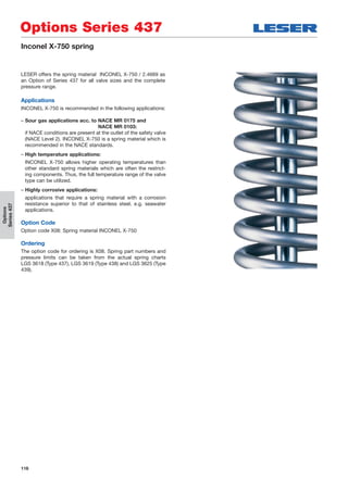
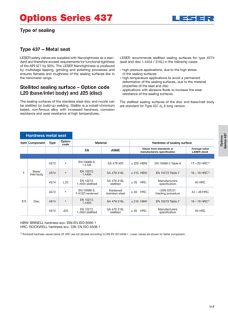
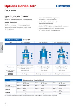
![119
Options
Series437
Soft seal selection
Soft seal selection
Abbrevation
ASTM 14
Trade name
(Designation)
Code
letter1)
Option-
code
Tmin Tmax
Application2)
[°C] [°F] [°C] [°F]
O-ring
CR Neoprene® K J21 -40 -40 100 212
Paraffins, mineral oils, silicon oils and
greases, water and aqueous solutions,
refrigerants, ozone
NBR
Buna-N®
(Nitrile-Butadiene)
N J30 -25 -13 100 212
Hydraulic oils, plant and animal fats and
oils
EPDM
Buna-EP®
(Ethylene-Propylene-
Dine)
D J22 -45 -49 150 302
Hot water and hot steam up to 150 °C,
302 °F, many organic and inorganic acids,
silicon oils and greases FDA conforming
compound
FKM
Viton®
(Fluorocarbon)
L J23 -20 -4 180 356
High temperatures (not hot steam),
mineral oils and greases, silicon oils and
greases, plant and animal oils and fats,
ozone FDA conforming compound on
request
FFKM
Kalrez®
(Perfluor)
C J20 0 32 250 482
Almost all chemicals, standard
compound is Kalrez® 6375 with steam
resistance FDA conforming compound
on request
Sealing plate
SP
VESPEL SP-1®
(Polyimide)
T J49 -270 -454 260 500
High-temperature and high-pressure
applications (no steam), chemical
resistance, see manufacturer's
specifications
PCTFE
KEL-F®
(Polychlorotri-
fluoroethylene)
G J48 -240 -400 150 302
Low-temperature and refrigeration
system applications, flammable media,
gaseous acid up to 50 bar, 725 psig
at 60 °C, 140 °F
PTFE
Teflon®
(Polytetrafluoro-
ethylene)
A J44 -200 -328 200 392 Almost all chemicals
Other not listed materials X For other materials, please contact your local representative or sales@leser.com
Options Series 437
1) The code letters are stamped on the disc (Item 1)
2) The pressure and temperature application range must be observed in all cases. The chemical resistance is based on specifications from the soft
seal manufacturer. LESER assumes no guarantee.](https://image.slidesharecdn.com/39dd659d-0f12-40d3-8ff4-3594fb05bf13-160314115249/85/LESER-Safety-Valve-Compact-Performance-Extended-Catalog-EN-119-320.jpg)
![120
CC
Outlet
A
G
InletG
Options
Series437
Options Series 437
Heating jacket
Heating jacket
Actual Orifice diameter d0 [mm] 6 10
Actual Orifice area A0 [mm2] 28.3 78.5
Actual Orifice diameter d0 [inch] 0.236 0.394
Actual Orifice area A0 [inch2] 0.044 0.122
Materials
Outlet body
Series 437
1.4404
316L
Heating jacket
1.4541
321
Connection
Couplings G 3/8" female 1.4571
DIN 2986 316Ti
Metric Units
Size outlet body 1/2" 3/4" 1"
Dimensions
A [mm] 50 50 50
C [mm] 61 71 71
G ["] 3/8
3/8
3/8
Operating conditions Operating pressure [bar]
Temperature 20 [°C] 25
210 [°C] 18
US Units
Size outlet body 1/2" 3/4" 1"
Dimensions
A [inch] 115/16 115/16 115/16
C [inch] 23/8 23/4 23/4
G ["] 3/8
3/8
3/8
Operating conditions Operating pressure [psig]
Temperature 68 [°F] 363
410 [°F] 261
Application and design
Safety valves in systems which need to be protected from
media that are viscous, sticky, or have the tendency to crystal-
lize out of solution can be fitted with a heating jacket.
The heating jacket is constructed with a welded design and
covers the outlet body (Item 2), allowing heating medias (steam,
heat transfer oil, etc.) to pass through the space created.
For the balanced bellows design a separate heating of the bon-
net spacer (Item 11) is not necessary. Sufficient heat will trans-
fer to the spacer by convection, due to the compact design of
the Series 437.](https://image.slidesharecdn.com/39dd659d-0f12-40d3-8ff4-3594fb05bf13-160314115249/85/LESER-Safety-Valve-Compact-Performance-Extended-Catalog-EN-120-320.jpg)
![121
Options
Series437
di
d4 d3
Options Series 437
Installing note
Horizontal fitting
For horizontal fitting certified
Attention! Only with outlet in direction downwards.
Inlet pipe dimension
Actual orifice diameter d0
[mm] 6 10
[inch2] 0.236 0.394
Actual orifice area A0
[mm2] 28.3 78.5
[inch2] 0.044 0.122
Inner Ø of pipe di
[mm] 8 12.5
[inch] 3/8" 1/2"
Screwed plugs – DIN ISO 228 /G
Male
Design of diameter d3 according to DIN 3852 – Part 2,
form A for small gasket.
Female
Design of diameter d4 according to DIN 3852 – Part 2,
form Y for small gasket.
Outlet connection
Caution!
To achieve the certified function and capacity it is important
to use an outlet pipe or an outlet connection
with an inner diameter ≥ than 16 mm / 5/8" inch.
Inner Ø of
connection
](https://image.slidesharecdn.com/39dd659d-0f12-40d3-8ff4-3594fb05bf13-160314115249/85/LESER-Safety-Valve-Compact-Performance-Extended-Catalog-EN-121-320.jpg)
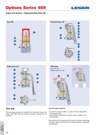


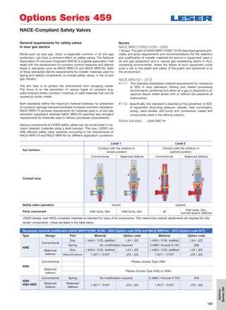
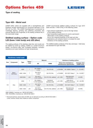
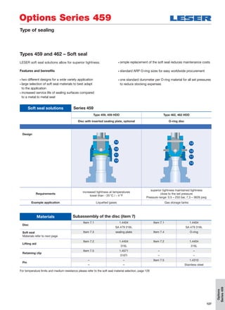
![128
Options
Series459
Options Series 459
Soft seal selection
Soft seal selection
Abbrevation
ASTM 14
Trade name
(Designation)
Code
letter1)
Option-
code
Tmin Tmax
Application2)
[°C] [°F] [°C] [°F]
O-ring
CR Neoprene® K J21 -40 -40 100 212
Paraffins, mineral oils, silicon oils and
greases, water and aqueous solutions,
refrigerants, ozone
NBR
Buna-N®
(Nitrile-Butadiene)
N J30 -25 -13 100 212
Hydraulic oils, plant and animal fats and
oils
EPDM
Buna-EP®
(Ethylene-Propylene-
Dine)
D J22 -45 -49 150 302
Hot water and hot steam up to 150 °C,
302 °F, many organic and inorganic acids,
silicon oils and greases FDA conforming
compound
FKM
Viton®
(Fluorocarbon)
L J23 -20 -4 180 356
High temperatures (not hot steam),
mineral oils and greases, silicon oils and
greases, plant and animal oils and fats,
ozone FDA conforming compound on
request
FFKM
Kalrez®
(Perfluor)
C J20 0 32 250 482
Almost all chemicals, standard
compound is Kalrez® 6375 with steam
resistance FDA conforming compound
on request
Sealing plate
SP
VESPEL SP-1®
(Polyimide)
T J49 -270 -454 260 500
High-temperature and high-pressure
applications (no steam), chemical
resistance, see manufacturer's
specifications
PCTFE
KEL-F®
(Polychlorotri-
fluoroethylene)
G J48 -240 -400 150 302
Low-temperature and refrigeration
system applications, flammable media,
gaseous acid up to 50 bar, 725 psig
at 60 °C, 140 °F
PTFE
Teflon®
(Polytetrafluoro-
ethylene)
A J44 -200 -328 200 392 Almost all chemicals
Other not listed materials X For other materials, please contact your local representative or sales@leser.com
1) The code letters are stamped on the disc (Item 1)
2) The pressure and temperature application range must be observed in all cases. The chemical resistance is based on specifications from the soft
seal manufacturer. LESER assumes no guarantee.](https://image.slidesharecdn.com/39dd659d-0f12-40d3-8ff4-3594fb05bf13-160314115249/85/LESER-Safety-Valve-Compact-Performance-Extended-Catalog-EN-128-320.jpg)
![129
Options
Series459
OutletG
Inlet
G
c c
A
Options Series 459
Heating jacket
Type 459, Type 462 Type 459 HDD, Type 462 HDD
Actual Orifice diameter d0 [mm] 6 9 13 17.5 6 9
Actual Orifice area A0 [mm2] 28.3 63.9 133 241 28.3 63.9
Actual Orifice diameter d0 [inch] 0.236 0.345 0.512 0.689 0.236 0.345
Actual Orifice area A0 [inch2] 0.044 0.099 0.206 0.374 0.044 0.099
Option code
H29 H29
Materials
Outlet body 1.4408 1.4408
CF8M CF8M
Heating jacket 1.4541 1.4541
321 321
Couplings 1.4571 1.4571
316Ti 316Ti
Dimensions
Metric units A [mm] 40 40
C [mm] 67 77
US units A [inch] 19/16 19/16
C [inch] 25/8 31/16
Connections
Ginlet Female thread DIN ISO 228-1 G 3/8" G3/8"
Female thread ASME B1.20.1 NPT 3/8" NPT 3/8"
Goutlet Female thread DIN ISO 228-1 3/8" 3/8"
Female thread ASME B1.20.1 NPT 3/8" NPT 3/8"
Operating conditions
max. operating pressure at 20°C [bar] 25 25
max. operating pressure at 210°C [bar] 18 18
max. operating pressure at 68°F [psig] 360 360
max. operating pressure at 410°F [psig] 260 260
Heating jacket
Safety valves in systems which need to be protected from
media that are viscous, sticky, or have the tendency to
crystallize out of solution can be fitted with a heating jacket.
The heating jacket is constructed with a welded design and
covers the outlet body (Item 2), allowing heating medias
(e. g. steam, heat transfer oil, etc.) to pass through the space
created.
For the balanced bellows design a separate heating of the
bonnet spacer (Item 11) is not necessary. Sufficient heat will
transfer to the spacer by convection, due to the compact
design of the Series 459.
If there is no risk of solidification of the media at the outlet a
safety valve without balanced bellows can be used as well.](https://image.slidesharecdn.com/39dd659d-0f12-40d3-8ff4-3594fb05bf13-160314115249/85/LESER-Safety-Valve-Compact-Performance-Extended-Catalog-EN-129-320.jpg)

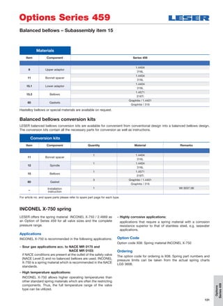
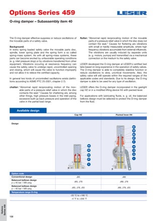
![133
Options
Series459
Options Series 459
O-ring damper – Subassembly item 40
Materials
Item Component Cap H2 Packed lever H4
1 Lever cover
– 1.4408
– CF8M
2 Cap H2
1.4404 1.4404
316L 316L
13 Parallel Pin
– A4
– Steel
14 Securing ring
– 1.4571
– 316Ti
15 Spindle
– 1.4404
– 316L
22 Opposite ring
1.4404 1.4404
316L 316L
27 Support bush
1.4404 –
316L –
27 Bush
– PTFE 15% glas
– PTFE 15% glas
82 Spring
1.4310 1.4310
Stainless steel Stainless steel
83 O-ring
FKM FKM
FKM FKM
Availability
Type 459, 459 HDD 459 462, 462 HDD 462
Actual Orifice diameter d0 [mm] 9 13 9 13
Actual Orifice area A0 [mm2] 63.9 133 63.9 133
Actual Orifice diameter d0 [inch] 0.345 0.512 0.345 0.512
Actual Orifice area A0 [inch2] 0.099 0.206 0.099 0.206
Option code
Cap H2
Packed lever H4
Set pressure range
Metric units [barg] 8.7 – 27.5 8.7 – 120 17.0 – 125 6 – 110
US units [psig] 261 – 400 126 – 1740 247 – 1810 98 – 1595
LESER has ensured proper performance of the O-ring damper through extensive tests at its certified test labs.
If an O-ring damper is required for a set pressure not listed in the table above further testing must be performed, which will
require a longer lead time; please contact sales@leser.com](https://image.slidesharecdn.com/39dd659d-0f12-40d3-8ff4-3594fb05bf13-160314115249/85/LESER-Safety-Valve-Compact-Performance-Extended-Catalog-EN-133-320.jpg)
![134
Options
Series459
Options Series 459
Availability
Item Component Option code
40 Lifting device H4 with adaptor for proximity switch M18 x 1 [mm] J39
94
Lift indicator
M18 x 1, used type = PEPPERL+FUCHS NJ5-18GK-N
J93
Operating chart
A, closed position B, open position
The lift indicator is positioned in front of the coupling
or control sleeve when the safety valve is closed.
When the safety valve opens or is lifted
(in both cases at least 1 mm / 0,04 inch),
lift indicator changes its signal. The signal also
changes if the lift indicator accidentally becomes
loosened or unscrewed (fail safe).
Closed position
Signal
Valve opens
High
Low
time
Open position
Valve lift min.
1 mm / 0.04 inch
Lift indicator
Lift indicators are useful devices for process automation. The lift
indicator is a useful device that can be used in process control
to monitor the operating status of a safety valve. To detect lift-
ing, LESER provides a special lifting device H4 incorporating a
proximity switch.The lift indicator will detect a safety valve lift
equal to or more than 1 mm / 0.04 in, which may be the result
of overpressure or of operation of the lifting device.
LESER provides inductive DC proximity switches, type
DIN EN 60947-5-6 (NAMUR) using two-wire technology. These
intrinsically safe proximity switches can be used in explosion
hazard area zone 0 ( II 1 D Ex iaD 20 T6). Other types of
proximity switch may be used. If a technical specification is
supplied along with the type of connection thread LESER can
verify compatibility.
For technical details of proximity switch refer to manufacturers
homepage: www.pepperl-fuchs.com
For assembly and adjustment refer to LESER works standard
WI 3323.02. Packed lever H4
94](https://image.slidesharecdn.com/39dd659d-0f12-40d3-8ff4-3594fb05bf13-160314115249/85/LESER-Safety-Valve-Compact-Performance-Extended-Catalog-EN-134-320.jpg)
![135
Options
Series459
Options Series 459
Lift restriction (lift restraining device)
A lift restriction may be needed to reduce the certified dis-
charge capacity of a safety valve to the required discharge
capacity. The lift restriction does not interfere with the operation
of the valve.
If a lift restriction is used the following requirements of codes
and standards must be considered.
Determining the restricted lift
Determining the restricted lift can be done by using:
– the “Diagram for evaluation of ratio of lift / flow diameter
(h/d0) in reference to the coefficient of discharge (Kdr/w)”.
– LESER sizing program “VALVESTAR®”
– LESER sizing web page www.valvestar.com
Requirements
Code / standard
EN ISO 4126-1,
section 5.1.3
ASME Code case 1945-4
AD 2000-Merkblatt A2,
section 10.3
Lift
≥ 30% full rated lift
not less than 1.0 mm / 1/16 inch
≥ 30% full rated lift
not less than 0.08 inch / 2.0 mm
≥ 30% full rated lift
not less than 1.0 mm / 1/16 inch
Coefficient of discharge
– – w [S/G] ≥ 0.08
– – w [L] ≥ 0.05
Name plate marking
Marking of reduced
coefficient of discharge
- Capacity replaced with
“Restricted capacity”
- Restricted lift =_____ inch / mm
Marking of reduced
coefficient of discharge
Design according to ASME
code case 1945-4
The restriction of valve capacity shall be permitted only by the use of a lift restraining device, which shall
limit valve lift and shall not otherwise interfere with flow throughout of the valve. The lift restricting device shall
be designed so that the adjustable feature can be mechanically locked and have access sealed.
Lift restrictions
Lift restriction by bush Lift restriction by gag
Design
Option code J51
Cap H2: J52
Packed lever H4: J50
Materials
Item Component
22 Bush
1.4404 –
316L –
93 Stud
– 1.4401
– B8M
96 Hex nut
– 1.4401
– 8M
22
96
93](https://image.slidesharecdn.com/39dd659d-0f12-40d3-8ff4-3594fb05bf13-160314115249/85/LESER-Safety-Valve-Compact-Performance-Extended-Catalog-EN-135-320.jpg)


The document provides information on LESER's Compact Performance safety relief valves, including: - Product types include Series 437 and 459 safety valves with threaded and flanged connections for steam, gas, and liquid applications. - Valves are designed for rapid opening with minimal overpressure and blowdown, and are approved by international standards organizations. - Materials, dimensions, pressure/temperature ratings, and other specifications are provided for the different valve types to suit a wide range of industrial applications up to 850 bar and 450°C. - Options allow customization for special connections, materials, and accessories to meet customer needs.


