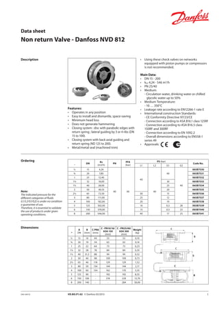
This document provides specifications for a Danfoss NVD 812 non-return valve, including:
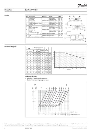
- Sizes range from DN15 to DN200 with Kvs values from 4.24 to 546 m3/h and PN ratings from 16 to 40 bar.
- Materials include stainless steel for casing, closing system, springs, stops/guides, and centering collars.
- Features include operating in any position, easy installation/dismantling, minimum head loss, no hammering, and metal/metal seals.
- Pressure and temperature ranges supported are up to 350°C and 40 bar, depending on size and fluid type.