Downloaded 11 times

![14
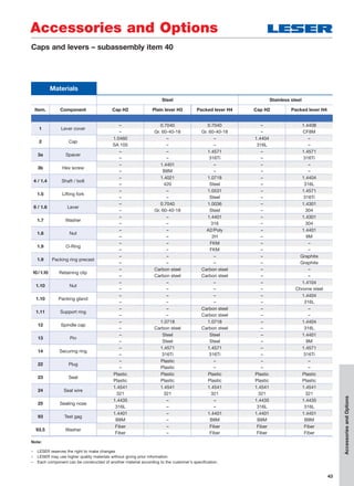
Article numbers
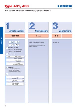
Type 433
Plain lever H3
Closed bonnet
Conventional design
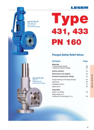
Type 431
Plain lever H3
Open bonnet
Conventional design
Type 433
Cap H2
Closed bonnet
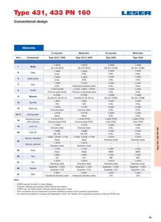
Balanced bellows design
Type 433
Cap H2
Closed bonnet
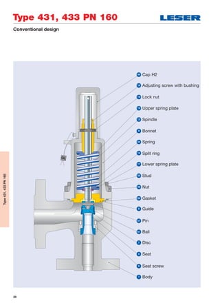
Conventional design
Type 433
Packed lever H4
Closed bonnet
Conventional design
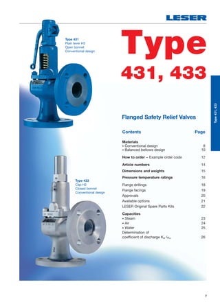
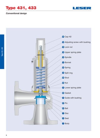
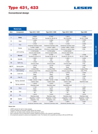
Type 431, 433
Type431,433
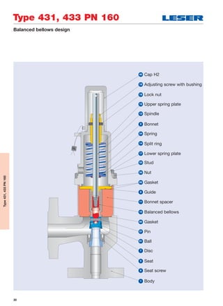
Article numbers
O-ring
disc
Metal
disc
DNI 15 15 20 25 32 40 50 65 80 100 125 150
DNO 15 15 20 25 32 40 50 65 80 100 125 150
Actual orifice diameter
d0 [mm]
12 12 18 18 18 23 29 37 46 60 74 92
Actual orifice area
A0 [mm2
]
113 113 254 254 254 416 661 1075 1662 2827 4301 6648
Body material: 0.6025 (cast iron)
Bonnet H2 Art. No. 4331. 8502 3992 4012 4022 4032 4042 4052 4062 4072 4082 – –
closed H3 Art. No. 4331. 8503 3993 4013 4023 4033 4043 4053 4063 4073 4083 – –
H4 Art. No. 4331. 8504 3994 4014 4024 4034 4044 4054 4064 4074 4084 – –
open H3 Art. No. 4311. 8505 3995 4015 4025 4035 4045 4055 4065 4075 4085 – –
Body material: 0.7043 (Ductile Gr. 60-40-18)
Bonnet H2 Art. No. 4335. 8532 8752 8762 8772 8782 8792 8802 8812 8822 8832 – –
closed H3 Art. No. 4335. 8533 8753 8763 8773 8783 8793 8803 8813 8823 8833 – –
H4 Art. No. 4335. 8534 8754 8764 8774 8784 8794 8804 8814 8824 8834 – –
open H3 Art. No. 4315. 8535 8755 8765 8775 8785 8795 8805 8815 8825 8835 – –
Body material: 1.0619 (WCB)
Bonnet H2 Art. No. 4332. 8512 4122 4142 4152 4162 4172 4182 4192 4202 4212 4222 4232
closed H3 Art. No. 4332. 8513 4123 4143 4153 4163 4173 4183 4193 4203 4213 4223 4233
H4 Art. No. 4332. 8514 4124 4144 4154 4164 4174 4184 4194 4204 4214 4224 4234
open H3 Art. No. 4312. 8515 4125 4145 4155 4165 4175 4185 4195 4205 4215 4225 4235
Body material: 1.4408 (CF8M)
Bonnet H2 Art. No. 4334. 8522 4252 4272 4282 4292 4302 4312 4322 4332 4342 – –
closed H4 Art. No. 4334. 8524 4254 4274 4284 4294 4304 4314 4324 4334 4344 – –](https://image.slidesharecdn.com/c97c0417-f0bb-484a-9c32-dfa612b48655-160314120302/85/Modulate_Action_Catalog_EN-14-320.jpg)
![15
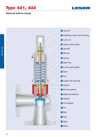
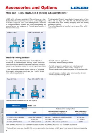
Type 431, 433
1)
Standard flange class. For other flange drillings, refer to page 18.
Conventional design Balanced bellows designSupport brackets
D
E
B
C
A
Type431,433
Dimensions and weights
Metric units
O-ring
disc
Metal
disc
DNI 15 15 20 25 32 40 50 65 80 100 125 150
DNO 15 15 20 25 32 40 50 65 80 100 125 150
Actual orifice diameter
d0 [mm]
12 12 18 18 18 23 29 37 46 60 74 92
Actual orifice area
A0 [mm2
]
113 113 254 254 254 416 661 1075 1662 2827 4301 6648
Weight 5 5 6 6 8 9 12 15 20 33 48 65
[kg] with bellows 6.3 6.3 6.4 6.4 8.4 9.6 13 16 21.6 35.6 52.1 78.4
Centre to face Inlet a 90 90 95 100 105 115 125 145 155 175 200 225
[mm] Outlet b 90 90 95 100 105 115 125 145 155 175 200 225
Height (H4) Standard H max. 310 310 315 320 325 335 360 475 530 605 745 870
[mm] Bellows H max. 362 362 345 350 360 390 425 535 600 680 825 965
Support brackets A 277
[mm] B 160
(Drilled only on request,
option code H42)
C Ø 18
D 278
E 21
Body material: 0.6025 (cast iron)
DIN flange1)
Inlet PN 16 – –
Outlet PN 16 – –
Body material: 0.7043 (Ductile Gr. 60-40-18)
DIN flange1)
Inlet PN 40 – –
Outlet PN 40 – –
Body material: 1.0619 (WCB)
DIN flange1)
Inlet PN 40
Outlet PN 40
Body material: 1.4408 (CF8M)
DIN flange1)
Inlet PN 40 – –
Outlet PN 40 – –](https://image.slidesharecdn.com/c97c0417-f0bb-484a-9c32-dfa612b48655-160314120302/85/Modulate_Action_Catalog_EN-15-320.jpg)
![16
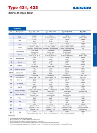
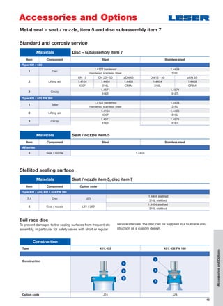
Type 431, 433
Type431,433
Pressure temperature ratings
Metric units
O-ring
disc
Metal
disc
DNI 15 15 20 25 32 40 50 65 80 100 125 150
DNO 15 15 20 25 32 40 50 65 80 100 125 150
Actual orifice diameter
d0 [mm]
12 12 18 18 18 23 29 37 46 60 74 92
Actual orifice area
A0 [mm2
]
113 113 254 254 254 416 661 1075 1662 2827 4301 6648
Body material: 0.6025 (cast iron)
DIN flange Inlet PN 16 – –
Outlet PN 16 – –
Minimum set pressure
p [barg] S/G/L 0.3 0.3 0.2 0.2 0.2 0.2 0.2 0.2 0.2 0.2 – –
Min. set pressure1)
p [barg] S/G/L 3.0 3.0 3.0 3.0 3.0 3.0 3.0 3.0 3.0 3.0 – –standard bellows
Min. set pressure
p [barg] S/G/L – – 2.0 2.0 2.0 1.8 1.9 1.8 1.8 1.2 – –low pressure bellows
Maximum set pressure
p [barg] S/G/L 16 16 16 16 16 16 16 16 16 16 – –
Max. set pressure
p [barg] S/G/L 16 16 16 16 16 16 16 16 16 16 – –with special spring
Temperature2)
min. [°C] -10 -10 – –
acc. to DIN EN max. [°C] +150 +300 – –
Body material: 0.7043 (Ductile Gr. 60-40-18)
DIN flange Inlet PN 40 – –
Outlet PN 40 – –
Minimum set pressure
p [barg] S/G/L 0.3 0.3 0.2 0.2 0.2 0.2 0.2 0.2 0.2 0.2 – –
Min. set pressure1)
p [barg] S/G/L 3.0 3.0 3.0 3.0 3.0 3.0 3.0 3.0 3.0 3.0 – –standard bellows
Min. set pressure
p [barg] S/G/L – – 2.0 2.0 2.0 1.8 1.9 1.8 1.8 1.2 – –low pressure bellows
Maximum set pressure
p [barg] S/G/L 40 40 40 40 40 40 40 35 35 30 – –
Max. set pressure
p [barg] S/G/L 40 40 40 40 40 40 40 40 35 30 – –with special spring
Temperature2)
min. [°C] -45 -60 – –
acc. to DIN EN max. [°C] +150 +350 – –
1)
Min. set pressure of standard bellows = max. set pressure of bellows for low set pressure.
2)
The temperature is limited by the soft seal material (see page 48). The values given here are valid for EPDM.
Between -10°C and the lowest specified application temperature, proceed acc. to AD 2000-Merkblatt W10.](https://image.slidesharecdn.com/c97c0417-f0bb-484a-9c32-dfa612b48655-160314120302/85/Modulate_Action_Catalog_EN-16-320.jpg)
![17
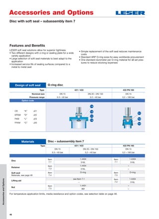
Type 431, 433
Type431,433
Metric units
O-ring
disc
Metal
disc
DNI 15 15 20 25 32 40 50 65 80 100 125 150
DNO 15 15 20 25 32 40 50 65 80 100 125 150
Actual orifice diameter
d0 [mm]
12 12 18 18 18 23 29 37 46 60 74 92
Actual orifice area
A0 [mm2
]
113 113 254 254 254 416 661 1075 1662 2827 4301 6648
Body material: 1.0619 (WCB)
DIN flange Inlet PN 40
Outlet PN 40
Minimum set pressure
p [barg] S/G/L 0.3 0.3 0.2 0.2 0.2 0.2 0.2 0.2 0.2 0.2 0.2 0.2
Min. set pressure1)
p [barg] S/G/L 3.0 3.0 3.0 3.0 3.0 3.0 3.0 3.0 3.0 3.0 3.0 3.0standard bellows
Min. set pressure
p [barg] S/G/L – – 2.0 2.0 2.0 1.8 1.9 1.8 1.8 1.2 1.2
on
requestlow pressure bellows
Maximum set pressure
p [barg] S/G/L 40 40 40 40 40 40 40 35 35 30 32 16
Max. set pressure
p [barg] S/G/L 40 40 40 40 40 40 40 40 35 30 32 16with special spring
Temperature2)
min. [°C] -45 -85
acc. to DIN EN max. [°C] +150 +450
Body material: 1.4408 (CF8M)
DIN flange Inlet PN 40 – –
Outlet PN 40 – –
Minimum set pressure
p [barg] S/G/L 0.3 0.3 0.2 0.2 0.2 0.2 0.2 0.2 0.2 0.2 – –
Min. set pressure1)
p [barg] S/G/L 3.0 3.0 3.0 3.0 3.0 3.0 3.0 3.0 3.0 3.0 – –standard bellows
Min. set pressure
p [barg] S/G/L – – 2.0 2.0 2.0 1.8 1.9 1.8 1.8 1.2 – –low pressure bellows
Maximum set pressure
p [barg] S/G/L 40 40 40 40 40 40 31.6 20.2 25 22 – –
Max. set pressure
p [barg] S/G/L 40 40 40 40 40 40 40 26 25 22 – –with special spring
Temperature2)
min. [°C] -45 -270 – –
acc. to DIN EN max. [°C] +150 +400 – –
1)
Min. set pressure of standard bellows = max. set pressure of bellows for low set pressure.
2)
The temperature is limited by the soft seal material (see page 48). The values given here are valid for EPDM.
Between -10°C and the lowest specified application temperature, proceed acc. to AD 2000-Merkblatt W10.
Pressure temperature ratings](https://image.slidesharecdn.com/c97c0417-f0bb-484a-9c32-dfa612b48655-160314120302/85/Modulate_Action_Catalog_EN-17-320.jpg)
![18
Type 431, 433
Type431,433
Flange drillings
Flange drillings
O-ring
disc
Metal
disc
DNI 15 15 20 25 32 40 50 65 80 100 125 150
DNO 15 15 20 25 32 40 50 65 80 100 125 150
Valve size 1
/2" x 1
/2" 1
/2" x 1
/2" 3
/4" x 3
/4" 1" x 1" 11
/4"x11
/4"11
/2"x11
/2" 2" x 2" 21
/2" x 21
/2" 3" x 3" 4" x 4" 5" x 5" 6" x 6"
Actual orifice diameter
d0 [mm]
12 12 18 18 18 23 29 37 46 60 74 92
Actual orifice area
A0 [mm2
]
113 113 254 254 254 416 661 1075 1662 2827 4301 6648
Body material: 0.6025 (cast iron)
Inlet DIN EN 1092
PN 10
* * * * * * * * * * * *
PN 16
* * * * * * * * * * * *
PN 25 – – – – – – – – – – – –
PN 40 – – – – – – – – – – – –
Outlet DIN EN 1092
PN 10
* * * * * * * * * * * *
PN 16
* * * * * * * * * * * *
Body material: 0.7043 (Ductile Gr. 60-40-18), 1.0619 (WCB), 1.4408 (CF8M)
Inlet
DIN EN 1092
PN 10
* * * * * * * H44 H44 H44 H44 H44
PN 16
* * * * * * * H45 H45 H45 H45 H45
PN 25
* * * * * * * * * * * *
PN 40
* * * * * * * * * * * *
ASME B16.5
CL150 H64 H64 H64 H64 H64 H64 H64 H64 H64 [H64] H64 H64
CL300 [H65] [H65] – H65 H65 – [H65] [H65] – – – –
Outlet
DIN EN 1092
PN 10
* * * * * * * H50 H50 H50 H50 H50
PN 16
* * * * * * * H51 H51 H51 H51 H51
PN 25
* * * * * * * * * * * *
PN 40
* * * * * * * * * * * *
ASME B16.5
CL150 H79 H79 H79 H79 H79 H79 H79 H79 H79 [H79] H79 H79
CL300 H80 H80 – H80 H80 – [H80] [H80] – – – –
For an explanation of the characters and symbols, refer to page 6.
Note: Flange drillings and facings always meet the requirements of the given flange standards.
Flange thickness and outside diameter may deviate from the standard.](https://image.slidesharecdn.com/c97c0417-f0bb-484a-9c32-dfa612b48655-160314120302/85/Modulate_Action_Catalog_EN-18-320.jpg)
![20
Approvals
Type 431, 433
Type431,433
Approvals
O-ring disc Metal disc
DNI 15 15 20 25 – 150
DNO 15 15 20 25 – 150
Actual orifice diameter d0 [mm] 12 12 18 18 – 92
Actual orifice area A0 [mm2
] 113 113 254 254 – 6648
Europe Coefficient of discharge Kdr
PED / DIN EN ISO 4126-1
12/2013
Approval-No. 072020111Z0008/0/06
S/G 0.59 0.62 0.29 0.38
L 0.47 0.48 0.19 0.25
Germany Coefficient of discharge w
PED /
AD 2000-Merkblatt A2
07/2012
Approval-No. TÜV SV 577
S/G 0.59 0.62 0.29 0.38
L 0.47 0.48 0.19 0.25
China Coefficient of discharge w
AQSIQ Approval-No. For current Approval-No. see www.leser.com
S/G 0.59 0.62 0.29 0.38
L 0.47 0.48 0.19 0.25
Eurasian Custom Union Coefficient of discharge w
EAC Approval-No. For current Approval-No. see www.leser.com
S/G 0.59 0.62 0.29 038
L 0.47 0.48 0.19 0.25
Classification societies Homepage
Bureau Veritas BV www.bureauveritas.com The valid Approval-No. changes
with each renewal of the approval.
For a sample certificate including
the valid certification number
see www.leser.com
ClassNK NIPPON Kaiji Kyokai NK www.classnk.or.jp
DNV GL www.dnvgl.com
Lloyd‘s Register EMEA LREMEA www.lr.org
Registro Italiano Navale RINA www.rina.org](https://image.slidesharecdn.com/c97c0417-f0bb-484a-9c32-dfa612b48655-160314120302/85/Modulate_Action_Catalog_EN-20-320.jpg)
![23
Type 431, 433
Type431,433
Metric units AD 2000-Merkblatt A2 [kg/h]
O-ring
disc
Metal
disc
DNI 15 15 20 25 32 40 50 65 80 100 125 150
DNO 15 15 20 25 32 40 50 65 80 100 125 150
Actual orifice diameter
d0 [mm]
12 12 18 18 18 23 29 37 46 60 74 92
Actual orifice area
A0 [mm2
]
113 113 254 254 254 416 661 1075 1662 2827 4301 6648
LEOS/G*)
[inch2
] 0.106 0.111 0.117 0.154 0.154 0.251 0.399 0.650 1.004 1.708 2.598 4.016
Set pressure [bar] Capacity [kg/h]
0.2 34 34 55 88 142 220 375 570 880
0.5 52 55 30 63 63 102 163 265 410 697 1060 1638
1 74 78 67 101 101 165 263 428 661 1125 1711 2645
2 118 125 129 170 170 278 442 720 1113 1893 2880 4452
3 161 168 177 232 232 379 603 981 1517 2581 3926 6068
4 200 210 221 290 290 473 752 1224 1892 3218 4895 7567
5 251 265 347 347 566 900 1465 2265 3853 5861 9058
6 293 308 404 404 659 1048 1706 2636 4485 6823 10545
7 333 350 459 459 750 1192 1940 2999 5102 7761 11996
8 374 394 516 516 842 1339 2179 3368 5730 8717 13473
9 415 437 572 572 934 1485 2418 3737 6358 9671 14948
10 456 480 629 629 1026 1632 2656 4105 6984 10624 16421
12 538 566 741 741 1210 1924 3132 4842 8237 12530 19366
14 618 650 852 852 1391 2211 3599 5563 9464 14395 22250
16 699 736 964 964 1574 2503 4074 6297 10714 16296 25189
18 781 822 1077 1077 1758 2795 4550 7033 11965 18200 28131
20 863 908 1190 1190 1942 3088 5027 7770 13218 20107
22 942 991 1299 1299 2121 3372 5489 8484 14434 21956
24 1024 1078 1412 1412 2306 3665 5967 9222 15690 23866
26 1106 1164 1525 1525 2491 3959 6445 9962 16949
28 1189 1251 1639 1639 2676 4254 6925 10704 18211
30 1271 1338 1753 1753 2862 4550 7407 11449 19478
32 1354 1425 1867 1867 3049 4847 7890 12195 20748
34
36
38
40
Calculation of the capacity for saturated steam acc. to AD 2000-Merkblatt A2 with 10% overpressure.
Capacities at 1 bar and lower are calculated at 0.1 bar overpressure.
Capacities – steam](https://image.slidesharecdn.com/c97c0417-f0bb-484a-9c32-dfa612b48655-160314120302/85/Modulate_Action_Catalog_EN-23-320.jpg)
![24
Type 431, 433
Type431,433
Metric units AD 2000-Merkblatt A2 [mn
3
/h]
O-ring
disc
Metal
disc
DNI 15 15 20 25 32 40 50 65 80 100 125 150
DNO 15 15 20 25 32 40 50 65 80 100 125 150
Actual orifice diameter
d0 [mm]
12 12 18 18 18 23 29 37 46 60 74 92
Actual orifice area
A0 [mm2
]
113 113 254 254 254 416 661 1075 1662 2827 4301 6648
LEOS/G*)
[inch2
] 0.106 0.111 0.117 0.154 0.154 0.251 0.399 0.650 1.004 1.708 2.598 4.016
Set pressure [bar] Capacity [mn
3
/h]
0.2 39 39 63 101 165 255 431 660 1019
0.5 64 67 35 74 74 120 191 311 481 819 1245 1925
1 93 93 80 121 121 197 313 510 788 1341 2039 3152
2 151 151 156 206 206 336 534 870 1344 2287 3478 5377
3 206 206 217 284 284 463 737 1199 1854 3153 4797 7414
4 246 258 272 356 356 582 925 1505 2327 3958 6021 9306
5 296 311 327 429 429 700 1113 1811 2800 4763 7245 11198
6 346 363 382 501 501 818 1301 2117 3273 5568 8469 13091
7 396 416 438 574 574 936 1489 2423 3746 6373 9694 14983
8 446 468 493 646 646 1055 1677 2729 4219 7177 10918 16875
9 496 521 548 718 718 1173 1865 3035 4692 7982 12142 18767
10 546 573 604 791 791 1291 2053 3342 5165 8787 13366 20659
12 646 679 714 936 936 1528 2429 3954 6111 10397 15815 24444
14 746 784 825 1081 1081 1764 2805 4566 7057 12006 18263 28228
16 846 889 935 1225 1225 2001 3181 5178 8003 13616 20711 32013
18 946 994 1046 1370 1370 2237 3557 5790 8949 15226 23160
20 1046 1099 1156 1515 1515 2474 3933 6402 9895 16835 25608
22 1146 1204 1267 1660 1660 2710 4309 7014 10842 18445 28057
24 1245 1309 1377 1805 1805 2947 4685 7626 11788 20055 30505
26 1345 1414 1488 1950 1950 3183 5061 8238 12734 21664 32954
28 1445 1519 1599 2095 2095 3420 5437 8851 13680 23274 35402
30 1545 1624 1709 2240 2240 3656 5813 9463 14626 24883 37850
32 1645 1729 1820 2384 2384 3893 6189 10075 15572 40299
34 1745 1834 1930 2529 2529 4130 6565 10687 16518
36 1845 1939 2041 2674 2674 4366 6941 11299
38 1945 2044 2151 2819 2819 4603 7317 11911
40 2045 2149 2262 2964 2964 4839 7693 12523
Calculation of the capacity for air acc. to AD 2000-Merkblatt A2 with 10% overpressure.
Capacities at 1 bar and lower are calculated at 0.1 bar overpressure.
Capacities – air](https://image.slidesharecdn.com/c97c0417-f0bb-484a-9c32-dfa612b48655-160314120302/85/Modulate_Action_Catalog_EN-24-320.jpg)
![25
Type 431, 433
Type431,433
Metric units AD 2000-Merkblatt A2 [103
kg/h]
O-ring
disc
Metal
disc
DNI 15 15 20 25 32 40 50 65 80 100 125 150
DNO 15 15 20 25 32 40 50 65 80 100 125 150
Actual orifice diameter
d0 [mm]
12 12 18 18 18 23 29 37 46 60 74 92
Actual orifice area
A0 [mm2
]
113 113 254 254 254 416 661 1075 1662 2827 4301 6648
LEOL*)
[inch2
] 0.127 0.129 0.115 0.152 0.152 0.248 0.394 0.641 0.991 1.686 2.564 3.963
Set pressure [bar] Capacity [103
kg/h]
0.2 1.77 1.77 2.89 4.60 7.50 11.6 19.7 30.0 46.3
0.5 2.09 2.14 1.90 2.51 2.51 4.09 6.51 10.6 16.4 27.8 42.4 65.5
1 2.84 2.90 2.58 3.39 3.39 5.54 8.81 14.3 22.2 37.7 57.4 88.7
2 4.01 4.10 3.65 4.80 4.80 7.84 12.5 20.3 31.3 53.3 81.1 125
3 4.91 5.02 4.47 5.88 5.88 9.60 15.3 24.8 38.4 65.3 99.3 154
4 5.67 5.79 5.16 6.79 6.79 11.1 17.6 28.7 44.3 75.4 115 177
5 6.34 6.48 5.77 7.59 7.59 12.4 19.7 32.1 49.6 84.3 128 198
6 6.95 7.09 6.32 8.31 8.31 13.6 21.6 35.1 54.3 92.4 140 217
7 7.50 7.66 6.82 8.98 8.98 14.7 23.3 37.9 58.6 99.8 152 235
8 8.02 8.19 7.30 9.60 9.60 15.7 24.9 40.6 62.7 107 162 251
9 8.51 8.69 7.74 10.2 10.2 16.6 26.4 43.0 66.5 113 172 266
10 8.97 9.16 8.16 10.7 10.7 17.5 27.9 45.3 70.1 119 181 280
12 9.82 10.0 8.93 11.8 11.8 19.2 30.5 49.7 76.8 131 199 307
14 10.6 10.8 9.65 12.7 12.7 20.7 33.0 53.7 82.9 141 215 332
16 11.3 11.6 10.3 13.6 13.6 22.2 35.2 57.4 88.7 151 229 355
18 12.0 12.3 10.9 14.4 14.4 23.5 37.4 60.8 94.0 160 243
20 12.7 13.0 11.5 15.2 15.2 24.8 39.4 64.1 99.1 169 257
22 13.3 13.6 12.1 15.9 15.9 26.0 41.3 67.3 104 177 269
24 13.9 14.2 12.6 16.6 16.6 27.1 43.2 70.2 109 185 281
26 14.5 14.8 13.2 17.3 17.3 28.3 44.9 73.1 113 192 292
28 15.0 15.3 13.6 18.0 18.0 29.3 46.6 75.9 117 200 304
30 15.5 15.9 14.1 18.6 18.6 30.3 48.2 78.5 121 207 314
32 16.0 16.4 14.6 19.2 19.2 31.3 49.8 81.1 125 324
34 16.5 16.9 15.0 19.8 19.8 32.3 51.4 83.6 129
36 17.0 17.4 15.5 20.4 20.4 33.2 52.9 86.0
38 17.5 17.9 15.9 20.9 20.9 34.2 54.3 88.4
40 17.9 18.3 16.3 21.5 21.5 35.0 55.7 90.7
Calculation of the capacity for water acc. to AD 2000-Merkblatt A2 with 10% overpressure at 20 °C.
Capacities at 1 bar and lower are calculated at 0.1 bar overpressure.
Capacities – water](https://image.slidesharecdn.com/c97c0417-f0bb-484a-9c32-dfa612b48655-160314120302/85/Modulate_Action_Catalog_EN-25-320.jpg)
![26
Type 431, 433
Type431,433
Determination of coefficient of discharge
in case of lift restriction or back pressure
h = Lift [mm]
d0 = Flow diameter [mm] of selected safety
valve see “Article numbers” table
h/d0 = Ratio of lift / flow diameter
pa0 = Back pressure [bara]
p0 = Set pressure [bara]
pa0/p0 = Ratio of back pressure / set pressure
Kdr = Coefficient of discharge
acc. to DIN EN ISO 4126-1
w = Coefficient of discharge
acc. to AD 2000-Merkblatt A2
Kb = Back pressure correction factor
acc. to API 520 Section 3.3
0.8
0.5
0.3
0.4
0.6
0.7
0.1
0
0.2
Kdr = αw = f (pa0/p0)
DN15 Metal disc
DN15 O-ring-disc
DN25 – 150
DN20
Ratio of back pressure / set pressure pa0 / p0
CoefficientofdischargeKdr/αw
0.3000.200 0.400 0.500 0.600 0.700
0.833
0.800 0.900
DN15, O-ring-disc, S/G
0.30.1
0.110 0.208
0.20
0.8
0.5
0.3
0.4
0.6
0.7
0.1
0
0.2
Kdr = αw = f (h/d0)
DN20, S/G
DN25 – DN150, S/G
Ratio of lift / flow diameter h / d0
CoefficientofdischargeKdr/αw
DN15, Metal disc, S/G
Diagram for evaluation of ratio of lift / flow diameter (h/d0) in reference
to the coefficient of discharge (Kdr/ w)
Diagram for evaluation of coefficient of discharge (Kdr/ w) or Kb in reference
to the ratio of back pressure / set pressure (pa0/p0)
Only valid for “steam/gases”
0.30.1 0.20
0.8
0.5
0.3
0.4
0.6
0.7
0.1
0
0.2
Kdr = αw = f (h/d0)
DN15, O-ring-disc, L
DN15, Metal disc, L
DN25 – DN150, L
DN20, L
0.110 0.208
Ratio of lift / flow diameter h / d0
CoefficientofdischargeKdr/αw
Only valid for “liquids”](https://image.slidesharecdn.com/c97c0417-f0bb-484a-9c32-dfa612b48655-160314120302/85/Modulate_Action_Catalog_EN-26-320.jpg)
![32
Type 431, 433 PN 160
Type431,433PN160
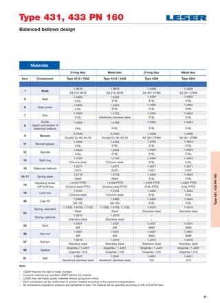
Article numbers
O-ring disc Metal disc
DNI 15 15
DNO 25 25
Actual orifice diameter
d0 [mm]
12 12
Actual orifice area
A0 [mm2
]
113 113
Body material: 1.0619 (WCB)
Bonnet H2 Art. No. 4332. 8572 8552
closed H3 Art. No. 4332. 8573 8553
H4 Art. No. 4332. 8574 8554
open H3 Art. No. 4312. 8575 8555
Body material: 1.4408 (CF8M)
Bonnet H2 Art. No. 4334. 8582 8562
closed H4 Art. No. 4334. 8584 8564
Article numbers
Type 433 PN 160
Plain lever H3
Closed bonnet
Conventional design
Type 431 PN 160
Plain lever H3
Open bonnet
Conventional design
Type 433 PN 160
Cap H2
Closed bonnet
Balanced bellows design
Type 433 PN 160
Cap H2
Closed bonnet
Conventional design
Type 433 PN 160
Packed lever H4
Closed bonnet
Conventional design](https://image.slidesharecdn.com/c97c0417-f0bb-484a-9c32-dfa612b48655-160314120302/85/Modulate_Action_Catalog_EN-32-320.jpg)
![33
Type 431, 433 PN 160
Conventional design Balanced bellows design
Type431,433PN160
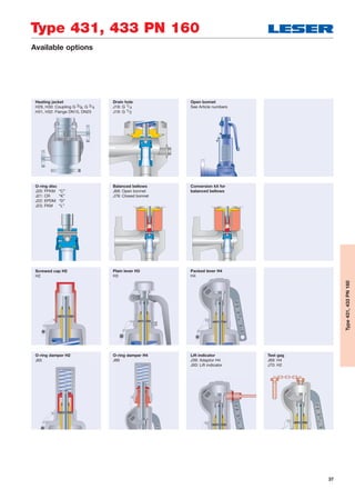
Dimensions and weights
Metric units
DNI 15
DNO 25
Actual orifice diameter
d0 [mm]
12
Actual orifice area
A0 [mm2
]
113
Weight 7
[kg] with bellows 8.4
Centre to face Inlet a 90
[mm] Outlet b 90
Height (H4) Standard H max. 307
[mm] Bellows H max. 359
Body material: 1.0619 (WCB)
DIN flange1)
Inlet PN 160
Outlet PN 40
Body material: 1.4408 (CF8M)
DIN flange1)
Inlet PN 160
Outlet PN 40
1)
Standard flange class. For other flange drillings, see page 35.](https://image.slidesharecdn.com/c97c0417-f0bb-484a-9c32-dfa612b48655-160314120302/85/Modulate_Action_Catalog_EN-33-320.jpg)
![34
Type 431, 433 PN 160
Type431,433PN160
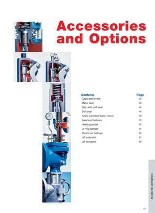
Pressure temperature ratings
Metric units
O-ring disc Metal disc
DNI 15 15
DNO 25 25
Actual orifice diameter
d0 [mm]
12 12
Actual orifice area
A0 [mm2
]
113 113
Body material: 1.0619 (WCB)
DIN flange Inlet PN 160
Outlet PN 40
Minimum set pressure
p [barg] S/G/L 0.3 0.3
Min. set pressure1)
p [barg] S/G/L 3 3standard bellows
Maximum set pressure
p [barg] S/G/L
“K”
142 144“D” “C” 85
“L”
Max. set pressure
p [barg] S/G/L
“K”
160 160with special spring “D” “C” 85
“L”
Temperature2)
min. [°C] -45 -60
acc. to DIN EN max. [°C] +150 +450
Body material: 1.4408 (CF8M)
DIN flange Inlet PN 160
Outlet PN 40
Minimum set pressure
p [barg] S/G/L 0.3 0.3
Min. set pressure1)
p [barg] S/G/L 3 3standard bellows
Max. set pressure
p [barg] S/G/L 85 85
Max. set pressure
p [barg] S/G/L
“K”
150 160with special spring “D” “C” 85
“L”
Temperature2)
min. [°C] -45 -270
acc. to DIN EN max. [°C] +150 +400
1)
Min. set pressure of standard bellows = max. set pressure of bellows for low set pressure.
2)
The temperature is limited by the soft seal material (see page 48). The values given here are valid for EPDM.
Between -10°C and the lowest specified application temperature, proceed as per AD 2000-Merkblatt W10.](https://image.slidesharecdn.com/c97c0417-f0bb-484a-9c32-dfa612b48655-160314120302/85/Modulate_Action_Catalog_EN-34-320.jpg)
![35
Type 431, 433 PN 160
Type431,433PN160
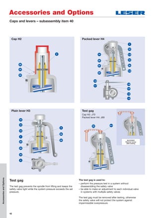
Flange drillings
DNI 15
DNO 25
Valve size 1/2" x 1"
Actual orifice diameter
d0 [mm]
12
Actual orifice area
A0 [mm2
]
113
Body material: 1.0619 (WCB), 1.4408 (CF8M)
Inlet DIN EN 1092
PN 16 H47
PN 40 H47
PN 63 *
PN 160 *
ASME B 16.5
CL300 H65
CL600 H67
Outlet
DIN EN 1092
PN 16 *
PN 40
*
ASME B16.51)
CL150 H79
CL300 H80
Flange drillings and facings
1)
LESER manufactures the groove at flanged valves by milling. If a customer demands a turned surface in the soil of the groove according to DIN EN 1092-1
an additional option code is necessary: “S01: soil of the groove drilled”.
2)
Smooth Finish is not defined in the effective standards.
For signs and symbols refer to page 6.
Note: Flange drillings and facings meet always the requirements of mentioned flange standards.
Flange thickness and outer diameter may vary from flange standard.
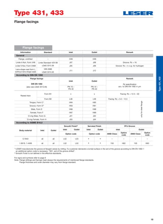
Flange facings
Information Standard Inlet Outlet Remark
General
Flange, undrilled – H38 H39
Linde-V-Nut, Form V48 Linde Standard 420-08
LDeS 3313.36
J07 J08 Groove: Rz = 16
Linde-V-Nut, Form V48A J05 J06 Groove: Rz = 4, e.g. for hydrogen
Lens-shape seal form L
(without lens-shape seal)
DIN 2696
LDeS 3313.35
J11 J12
According to DIN EN 1092
Flange facings
(also see LDeS 3313.40)
Inlet Outlet
Remark
Rz specification
acc. to DIN EN 1092 in μmPN 63 –
PN 160
PN 40
Raised face
Form B1 –
* Facing: Rz = 12.5 – 50
Form B2
* L38 Facing: Rz = 3.2 – 12.5
onlyforsteelflange
Tongue, Form C1)
H94 H92
Groove, Form D1)
H93 H91
Male, Form E H96 H98
Female, Form F H97 H99
O-ring Male, Form G J01 J02
O-ring Female, Form H J03 J04
According to ASME B16.5
Body material Inlet Outlet
Smooth Finish2)
Serrated Finish RTJ-Groove
Inlet Outlet Inlet Outlet Inlet Outlet
Option code Option code ANSI Class Option code ANSI Class Option code
1.0619, 1.4408 all all L52 L53
* * 150 H62 150 H63](https://image.slidesharecdn.com/c97c0417-f0bb-484a-9c32-dfa612b48655-160314120302/85/Modulate_Action_Catalog_EN-35-320.jpg)
![36
Type 431, 433 PN 160
Type431,433PN160
Approvals
Approvals
O-ring disc Metal disc
DNI 15 15
DNO 25 25
Actual orifice diameter d0 [mm] 12 12
Actual orifice area A0 [mm2
] 113 113
Europe Coefficient of discharge Kdr
PED / DIN EN ISO 4126-1
12/2013
Approval-No. 072020111Z0008/0/06
S/G 0.59 0.62
L 0.47 0.48
Germany Coefficient of discharge w
PED /
AD 2000-Merkblatt A2
07/2012
Approval-No. TÜV SV 577
S/G 0.59 0.62
L 0.47 0.48
China Coefficient of discharge w
AQSIQ Approval-No. For current Approval-No. see www.leser.com
S/G 0.59 0.62
L 0.47 0.48
Eurasian Custom Union Coefficient of discharge w
EAC Approval-No. For current Approval-No. see www.leser.com
S/G 0.59 0.62
L 0.47 0.48
Classification societies Homepage
Bureau Veritas BV www.bureauveritas.com The valid Approval-No. changes
with each renewal of the approval.
For a sample certificate including
the valid certification number
see www.leser.com
ClassNK NIPPON Kaiji Kyokai NK www.classnk.or.jp
DNV GL www.dnvgl.com
Lloyd‘s Register EMEA LREMEA www.lr.org
Registro Italiano Navale RINA www.rina.org](https://image.slidesharecdn.com/c97c0417-f0bb-484a-9c32-dfa612b48655-160314120302/85/Modulate_Action_Catalog_EN-36-320.jpg)
![38
Type 431, 433 PN 160
Type431,433PN160
Spare parts
Spare parts
O-ring disc Metal disc
DNI 15 15
DNO 25 25
Actual orifice diameter
d0 [mm]
12 12
Actual orifice area
A0 [mm2
]
113 113
Disc (item 7): Metal seat Material-No. / Art. No.
Disc 1.4122 – 230.9339.9000
Detachable lifting aid 1.4404 – 230.9349.9000
Disc (item 7): Soft seal Material-No. / Art. No.
Disc CR “K” 230.2949.9053 –
EPDM “D” 230.2949.9042 –
FKM “L” 230.2949.9073 –
FFKM “C” 230.2949.9091 –
O-ring (item 7.4): Soft seal Material-No. / Art. No.
O-ring CR “K” 502.0107.2653 –
EPDM “D” 502.0107.2642 –
FKM “L” 502.0107.2673 –
FFKM “C” 502.0107.2691 –
Bellows (item 15): 1.4571 Material-No. / Art. No.
Standard bellows 400.6349.0000 400.6349.0000
Conversion kit, standard1)
Please specify application conditions
Low pressure bellows – –
Conversion kit low pressure1)
– –
Gasket – body / bonnet (item 60) Material-No. / Art. No.
Gasket Graphite + 1.4401 500.0407.0000 500.0407.0000
Option code L68 Gylon (PTFE compliance) 500.0405.0000 500.0405.0000
Ball (item 61) Material-No. / Art. No.
Ball Ball Ø [mm] 6 6
1.4404 510.0104.0000 510.0104.0000
Split ring (item 14) Material-No. / Art. No.
Split ring Spindle Ø [mm] 12 12
1.4404 251.0149.0000 251.0149.0000
Pin (item 57) Material-No. / Art. No.
Pin 1.4310 480.0505.0000 480.0505.0000
O-ring damper Material-No. / Art. No.
Conversion kit H2 5021.1060 5021.1060
Conversion kit H4 5021.1064 5021.1064
Item Components No.
8 Guide; upper connection of balanced bellows 1
11 Bonnet spacer 1
12 Spindle 1
15 Bellows 1
55 Stud 4
60 Gasket 2
Instruction guide WI 3037.05 1
Refer to page page 30.](https://image.slidesharecdn.com/c97c0417-f0bb-484a-9c32-dfa612b48655-160314120302/85/Modulate_Action_Catalog_EN-38-320.jpg)
![39
Type 431, 433 PN 160
Type431,433PN160
Capacities
Metric units AD 2000-Merkblatt A2
O-ring disc Metal disc O-ring disc Metal disc O-ring disc Metal disc
DN 15 15 15 15 15 15
DNO 25 25 25 25 25 25
Actual orifice diameter
d0 [mm]
12 12 12 12 12 12
Actual orifice area
A0 [mm2
]
113 113 113 113 113 113
LEOS/G/L*)
[inch2
] 0.106 0.111 0.106 0.111 0.127 0.129
Set pressure Capacities Capacities Capacities
Steam
saturated
[kg/h]
Air
0°C and 1013 mbar
[mn
3
/h]
Water
20°C
[103
kg/h]
[bar]
0.2
0.5 52 55 64 67 2.09 2.14
1 74 78 93 93 2.84 2.90
2 118 125 151 151 4.01 4.10
3 161 168 206 206 4.91 5.02
4 200 210 246 258 5.67 5.79
5 251 296 311 6.34 6.48
6 293 346 363 6.95 7.09
7 333 396 416 7.50 7.66
8 374 446 468 8.02 8.19
9 415 496 521 8.51 8.69
10 456 546 573 8.97 9.16
12 538 646 679 9.82 10.0
14 618 746 784 10.6 10.8
16 699 846 889 11.3 11.6
18 781 946 994 12.0 12.3
20 863 1046 1099 12.7 13.0
22 942 1146 1204 13.3 13.6
24 1024 1245 1309 13.9 14.2
26 1106 1345 1414 14.5 14.8
28 1189 1445 1519 15.0 15.3
30 1271 1545 1624 15.5 15.9
32 1354 1645 1729 16.0 16.4
34 1433 1745 1834 16.5 16.9
36 1517 1845 1939 17.0 17.4
38 1600 1945 2044 17.5 17.9
40 1684 2045 2149 17.9 18.3
50 2109 2545 2674 20.1 20.5
60 2537 3045 3200 22.0 22.4
70 2981 3545 3725 23.7 24.2
80 3430 4045 4250 25.4 25.9
90 3901 4544 4775 26.9 27.5
100 5044 5301 28.4 29.0
120 6044 6351 31.1 31.7
140 7044 7402 33.6 34.3
160 8043 8452 35.9 36.6
Calculation of the capacity for steam, gases, and liquids acc. to AD 2000-Merkblatt A2 with 10% overpressure.
Capacities at 1 bar and lower are calculated at 0.1 bar overpressure.](https://image.slidesharecdn.com/c97c0417-f0bb-484a-9c32-dfa612b48655-160314120302/85/Modulate_Action_Catalog_EN-39-320.jpg)
![40
Type 431, 433 PN 160
Type431,433PN160
Determination of coefficient of discharge
in case of lift restriction or back pressure
0.8
0.5
0.3
0.4
0.6
0.7
0.1
0
0.2
Ratio of back pressure / set pressure pa0 / p0
CoefficientofdischargeKdr/αw
DN15 Metal disc
DN15 O-ring-disc
0.3000.200 0.400 0.500 0.600 0.700 0.800 0.900
Kdr = αw = f (pa0/p0)
0.717 0.772
DN15, O-ring-disc, S/G
0.30.1 0.20
0.8
0.5
0.3
0.4
0.6
0.7
0.1
0
0.2
Kdr = αw = f (h/d0)
Ratio of lift / flow diameter h / d0
CoefficientofdischargeKdr/αw
DN15, Metal disc, S/G
Diagram for evaluation of ratio of lift / flow diameter (h/d0) in reference
to the coefficient of discharge Kdr/ w)
Diagram for evaluation of coefficient of discharge (Kdr/ w) or Kb in reference
to the ratio of back pressure / set pressure (pa0/p0)
Only valid for “steam/gases”
0.30.1 0.20
0.8
0.5
0.3
0.4
0.6
0.7
0.1
0
0.2
Kdr = αw = f (h/d0)
Ratio of lift / flow diameter h / d0
CoefficientofdischargeKdr/αw
DN15, Metal disc, L
DN15, O-ring-disc, L
Only valid for “liquids”
h = Lift [mm]
d0 = Flow diameter [mm] of selected safety
valve see “Article numbers” table
h/d0 = Ratio of lift / flow diameter
pa0 = Back pressure [bara]
p0 = Set pressure [bara]
pa0/p0 = Ratio of back pressure / set pressure
Kdr = Coefficient of discharge
acc. to DIN EN ISO 4126-1
w = Coefficient of discharge
acc. to AD 2000-Merkblatt A2
Kb = Back pressure correction factor
acc. to API 520 Section 3.3](https://image.slidesharecdn.com/c97c0417-f0bb-484a-9c32-dfa612b48655-160314120302/85/Modulate_Action_Catalog_EN-40-320.jpg)
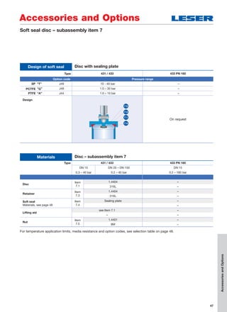
![48
Accessories and Options
Soft seal
Sealing plate
SP
VESPEL SP-1® 3)
(Polyimide)
T J49 -270 300
High-temperature and high-pressure applications
(no steam), chemical resistance, see manufacturer's
specifications
PCTFE
KEL-F®
(Polychlorotri-
fluoroethylene)
G J48 -240 204
Low-temperature and refrigeration system applications,
flammable media, gaseous acid up to 50 bar, 725 psig
at 60 °C, 140 °F
PTFE
Teflon®
(Polytetrafluoro-
ethylene)
A J44 -184 150 Almost all chemicals
Other not listed materials X For other materials, please contact your local representative or sales@leser.com.
AccessoriesandOptions
Soft seal selection O-ring
Abbrevation
ASTM 14
Trade name
(Designation)
Code
letter1)
Option
code
Tmin Tmax
Application2)
[°C] [°C]
O-ring
CR Neoprene®
K J21 -40 100
Paraffins, mineral oils, silicon oils and greases,
water and aqueous solutions, refrigerants, ozone
NBR
Buna-N®
(Nitrile-Butadiene)
N J30 -25 100 Hydraulic oils, plant and animal fats and oils
EPDM
Buna-EP
(Ethylene-Propylene-
Dine)
D J22 -45 150
Hot water and hot steam up to 150 °C, 302 °F,
many organic and inorganic acids, silicon oils and
greases FDA conforming compound
FKM
Viton®
(Fluorocarbon)
L J23 20 180
High temperatures (not hot steam), mineral oils and
greases, silicon oils and greases, plant and animal oils
and fats, ozone FDA conforming compound on request
FFKM
Kalrez®
(Perfluor)
C J20 0 250
Almost all chemicals, standard compound is Kalrez®
6375 with steam resistance FDA conforming compound
on request
1)
The code letters are stamped on the disc (Item 1)
2)
The pressure and temperature application range must be observed in all cases. The chemical resistance is based on specifications from the soft
seal manufacturer. LESER assumes no guarantee.
3)
Only for DN 25, 1" x 2".](https://image.slidesharecdn.com/c97c0417-f0bb-484a-9c32-dfa612b48655-160314120302/85/Modulate_Action_Catalog_EN-48-320.jpg)
![53
Accessories and Options
AccessoriesandOptions
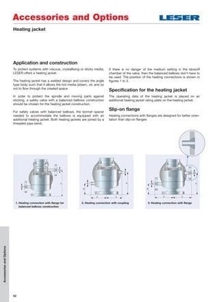
Heating jacket
Metric units
DNE 15 15 20 25 32 40 50 65 80 100 125 150
Inlet valve size 1
/2" x 1
/2" 1
/2" x 1
/2" 3
/4" x 3
/4" 1" x 1" 11
/4" x 11
/4" 11
/2" x 11
/2" 2" x 2" 21
/2" x 21
/2" 3" x 3" 4" x 4" 5" x 5" 6" x 6"
Actual orifice diameter
d0 [mm]
12 12 18 18 18 23 29 37 46 60 74 92
Series 433 Dimensions
[mm] A 95 95 95 95 105 120 130 150 170 165 – –
B 65 65 65 65 65 75 75 80 80 80 – –
C 83 83 83 83 95 95 95 110 120 145 – –
D 131 131 130 134 142 163 180 209 224 300 – –
E 110 110 110 110 120 121 121 136 150 176 – –
Slip-on flange DN 15 15 15 15 15 15 15 15 25 25 – –
[inch] Coupling G 3/8 3/8 3/8 3/8 3/8 3/8 3/8 3/8 3/4 3/4 – –
Series 433 Operating pressure [bar]
Operating 20°C 25 25 25 25 25 25 25 15 15 15 – –
temperature 300°C 18 18 18 18 18 18 18 11 11 11 – –
Heating jacket
DNI 15 15 20 25 32 40 50 65 80 100 125 150
Inlet valve size 1
/2" x 1
/2" 1
/2" x 1
/2" 3
/4" x 3
/4" 1" x 1" 11
/4"x11
/4" 11
/2"x11
/2" 2" x 2" 21
/2"x21
/2" 3" x 3" 4" x 4" 5" x 5" 6" x 6"
Actual orifice diameter
d0 [mm]
12 12 18 18 18 23 29 37 46 60 74 92
Materials
Body 1.0619 1.0619 1.0619
Series 433 1.4408 1.4408 1.4408 1.4408 1.4408 1.4408 1.4408 optional optional optional – –
1.4408 1.4408 1.4408
Heating jacket 1.4541
321
Connections
Slip-on flange
DIN
Option code
DN 15,
PN 25
1.4571, 1.4404
H 31
316Ti, 316L – – – –
H 32
DN 25,
PN 25
– 1.4571, 1.4404
– 316Ti, 316L – –
Slip-on flange
ANSI
K 31
1
/2",
CL150
1.4404
316L – – – –
K 32
1",
CL150
– 1.4404
– 316L – –
Coupling
DIN 2986
H 29 G 3/8"
1.4571
316Ti – – – –
H 30 G 3/4"
– 1.4571
– 316Ti – –
Heating jacket
Bonnet spacer
H 33
1.4404
316L – –](https://image.slidesharecdn.com/c97c0417-f0bb-484a-9c32-dfa612b48655-160314120302/85/Modulate_Action_Catalog_EN-53-320.jpg)
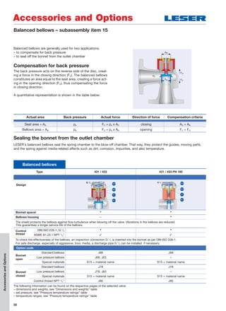
![56
Accessories and Options
AccessoriesandOptions
Materials
Valve size DN 20 – 100 DN 20 – 150
Option code J79 J87 (DN 100 J87 + S70)
Item Component
70 Elastomer bellows
70 EPDM 281 45 NBR 670
70 EPDM 281 45 NBR 670
71 Hose clamp
1.4301 1.4301
304 304
72 Hose clamp
1.4301 1.4301
304 304
Operating conditions
Temperature ranges [°C] -50 to +130 -25 to +100
Set pressure max. [barg] 10
Built-up [barg] up to 3
Application
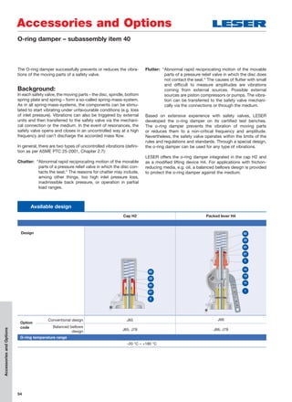
Bellows seal the spring chamber to the blow-off chamber. That
way,theyprotecttheguides,movingparts,andthespringagainst
media-related affects such as dirt, corrosion, and impurities.
The elastomer bellows provides a cost-effective alternative to
the balanced bellows.
The range of applications for the elastomer bellows is limited by:
– Chemical resistance
– Medium temperature
– Set pressure
– Back pressure
Elastomer bellows
Design
Construction
Easy, compact, and single-ply construction facilitates installation in small blow-off chambers.
The one-piece design also facilitates easy replacement and extends the service life.
Flexibility
The special shape of the elastomer bellows provides good spindle mobility and
prevents wear and tear.
Inspection hole
To check the effectiveness of the bellows, an inspection hole (Ø 10 mm) is put into the bonnet.
This makes it possible to check the seal tightness of the bellows.
In the event of a fault in the bellows, the medium leaks from this hole.
Construction height No change
70
72
71
Elastomer bellows](https://image.slidesharecdn.com/c97c0417-f0bb-484a-9c32-dfa612b48655-160314120302/85/Modulate_Action_Catalog_EN-56-320.jpg)
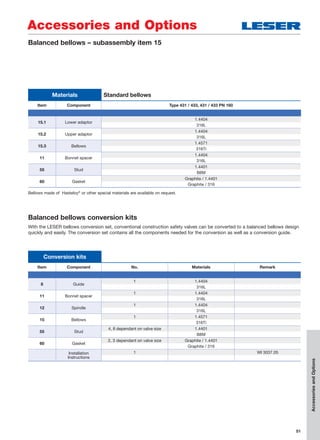
![57
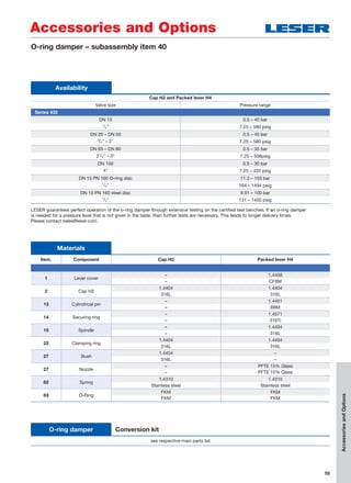
The lift indicator is used in the process technology to moni-
tor the operating condition of a safety valve. Depending
on the type of valve, LESER equips the packed lever H4
or the bonnets with the receptacle for the lift indicator. For
safety valves with lift indicators, the opening of the valve
during opening or the lifting operation is signalled as of a spe-
cific lift (min. 1mm).
LESER uses inductive DC lift indicators with two-wire technology
TypeDINEN60947-5-6(NAMUR).Theindicatorsareapprovedfor
use in explosion-prone areas of Zone 0 ( II 1 D Ex iaD 20 T6).
Other indicators that meet customer specifications can be
used.
Technical data for lift indicators can be found on the manufac-
turer’s homepage:
www.pepperl-fuchs.com
Gas-tight construction on request!
For installation instructions for lift indicators, see WI 3323.02.
94
Packed lever H4
Accessories and Options
AccessoriesandOptions
Lift indicator
Availability
Item. Name Option code
40 Packed lever H4 with receptacle for lift indicator M!8 x 1 [mm] J39
94
Lift indicator
M18 x 1, used type = PEPPERL+FUCHS NJ5-18GK-N
J93
Functional diagram
A, closed B, open
For a closed valve, the lift indicator is positioned on the side,
in front of the coupling or the control sleeve.
If the safety valve opens or if the safety valve is vented
(in both cases, min. 1 mm)
the lift indicator changes its state and switches.
If the lift indicator unscrews, e.g. due to vibrations,
there is also a switching operation.
closed
Signal
Valve opens
High
Low
Time
open
Valve lift, min. 1
mm / 0.04 inch](https://image.slidesharecdn.com/c97c0417-f0bb-484a-9c32-dfa612b48655-160314120302/85/Modulate_Action_Catalog_EN-57-320.jpg)
![58
Accessories and Options
The Lift restriction is used to adjust the safety valve to the
required discharge mass flow and does not affect the operation
of the safety valve.
A lift stopper must meet the requirements of the following
codes and standards.
AccessoriesandOptions
Lift restriction
Lift restriction
Lift restriction by bush Lift restriction by gag
Design
Option code J51
Cap H2: J52
Packed lever H4: J50
Availability
Series 433
Materials
Item. Component
22 Bush
1.4404 –
316L –
93 Stud
– 1.4401
– B8M
96 Nut
– 1.4401
– 8M
22
96
93
Requirements
Code / Standards EN ISO 4126-1, Section 5.1.3 ASME Code case 1945-4 AD 2000-Merkblatt A2, Section 10.3
Lift
≥ 30% of the full lift
not less than 1.0 mm
≥ 30% of the full lift
not less than 2.0 mm
≥ 30% of the full lift
not less than 1.0 mm
Coefficient of discharge – – w [S/G] ≥ 0.08
– – w [L] ≥ 0.05
Name plate marking
Identification of the reduced
coefficient of discharge
– Capacity replaced by
“Limited capacity”
– Limited lift =____ mm
Identification of the reduced
coefficient of discharge
Design according to
EN ISO 4126-1
For valves with a lift stopper to adapt to the required discharge mass flow, this device must not have an
adverse effect on the operation of the valve. If it is adjustable, the lift stopper device must be setup
such that the adjustable part can be mechanically secured and sealed.
The lift stopper device must be installed and sealed by the manufacturer.](https://image.slidesharecdn.com/c97c0417-f0bb-484a-9c32-dfa612b48655-160314120302/85/Modulate_Action_Catalog_EN-58-320.jpg)


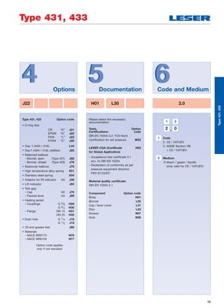
This document provides information on LESER Series 433 safety relief valves, including: - An overview of the valve finder tool for selecting the appropriate product based on application needs. - Descriptions of the conventional and balanced bellows designs for Type 433 valves, with materials lists and diagrams of key components. - Information on ordering, specifications, dimensions, pressure/temperature ratings, flange options, approvals, accessories, spare parts, and flow capacity charts. - Guidance on applications, general design features, and how to interpret codes and symbols used in the documentation.


