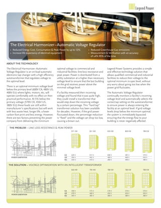
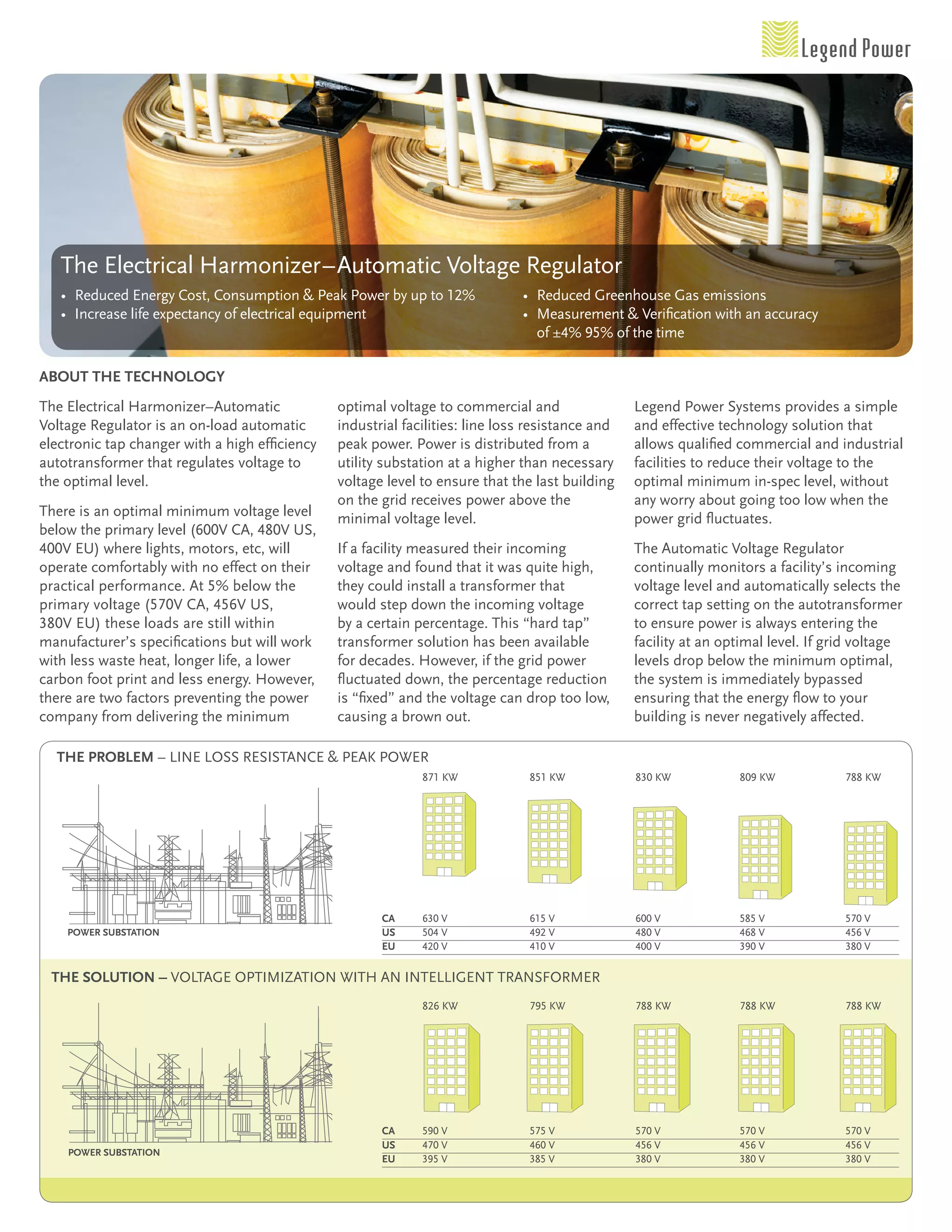
the electrical harmonizer–automatic Voltage Regulator
   • Reduced energy cost, consumption & Peak Power by up to 12%                • Reduced greenhouse gas emissions
   • increase life expectancy of electrical equipment                          • measurement & Verification with an accuracy
                                                                                 of ±4%	95% of the time

abouT The Technology
the electrical harmonizer–automatic             optimal voltage to commercial and                 Legend Power systems provides a simple
Voltage Regulator is an on-load automatic       industrial facilities: line loss resistance and   and effective technology solution that
electronic tap changer with a high efficiency   peak power. Power is distributed from a           allows qualified commercial and industrial
autotransformer that regulates voltage to       utility substation at a higher than necessary     facilities to reduce their voltage to the
the optimal level.                              voltage level to ensure that the last building    optimal minimum in-spec level, without
                                                on the grid receives power above the              any worry about going too low when the
there is an optimal minimum voltage level       minimal voltage level.                            power grid fluctuates.
below the primary level (600V	CA,	480V	US,
400V	EU) where lights, motors, etc, will        if a facility measured their incoming             the automatic Voltage Regulator
operate comfortably with no effect on their     voltage and found that it was quite high,         continually monitors a facility’s incoming
practical performance. at 5% below the          they could install a transformer that             voltage level and automatically selects the
primary voltage (570V	CA,	456V	US,	             would step down the incoming voltage              correct tap setting on the autotransformer
380V	eU) these loads are still within           by a certain percentage. this “hard tap”          to ensure power is always entering the
manufacturer’s specifications but will work     transformer solution has been available           facility at an optimal level. if grid voltage
with less waste heat, longer life, a lower      for decades. however, if the grid power           levels drop below the minimum optimal,
carbon foot print and less energy. however,     fluctuated down, the percentage reduction         the system is immediately bypassed
there are two factors preventing the power      is “fixed” and the voltage can drop too low,      ensuring that the energy flow to your
company from delivering the minimum             causing a brown out.                              building is never negatively affected.

  The Problem – Line Loss Resistance & Peak PoweR
                                                       	      871	kW	           851	kW	           830	kW	          809	kW	           788	kW


                                                       CA	    630	V	            615	V	            600	V	           585	V	            570	V
    Power SubSTaTion                                   US	    504	V	            492	V	            480	V	           468	V	            456	V
                                                       EU	    420	V	            410	V	            400	V	           390	V	            380	V

 The SoluTion – VoLtage oPtimization with an inteLLigent tRansfoRmeR
                                                       	      826	kW	           795	kW	           788	kW	          788	kW	           788	kW


                                                       CA	    590	V	            575	V	            570	V	           570	V	            570	V
                                                       US	    470	V	            460	V	            456	V	           456	V	            456	V
    Power SubSTaTion
                                                       EU	    395	V	            385	V	            380	V	           380	V	            380	V
ProducT SPecificaTion SheeT
PRodUct nUmbeR                                                          400	               500	             600	              700	                  800	           900	             1000
maximum Primary Voltage options                                                                                     600,	480,	400*
frequency (hz) options                                                                                                  60,	50*
taps                                                                                                                –2%	–4%	–6%
automatic bypass (0%)                                                                                                     Yes
tap change method                                                                      zero crossing, on-Load, fully automatic, Processor controlled, electronic
thd (v) on tap change                                                                                                   <0.5%
thd (current) on tap change                                                                                             <2.0%
efficiency                                                                                                              99.89%
ambient temperature                                                                                    0°c to 40°c – relative humidity 0	–	95%
cooling method                                                                                                        convection
system configuration                                                                                         3 phase, 4 wire input/output
switching speed (msec)                                                                                                   <100
Repetitive full Range tap changing interval (sec)                                                                         30
non Repetitive tap changing interval (sec)                                                                                10
coil construction                                                                                                        form
insulation class                                                                                                       180 (h)
installation methods                                                                           floor mount, ceiling mount, seismic frame, split module
maximum system Load current Rating (amps)                                400*	              500	            600*	             700*	           800	            900*	                   1000*
harmonizer current Rating (amps)                                    400,	300*	              400	            500	              750	            750	            750	               750,	1000*
system / breaker current (amps)                                          400	               500	            600	              700	            800	            900	                    1000
Reg coil Ω @ 25°c / 6%                                                0.105	              0.094	          0.084	            0.049	          0.049	          0.049	                    0.032
% impedance @ 115°c                                                     0.16	               0.16	           0.17	            0.18	           0.18	           0.18	                     0.22
temp rise @ full Load                                                     38	                 38	             39	              42	             42	             42	                       43

mechanicaL (approximate – will vary with installation configuration)
weight (kg/lbs)                                                     355/783	            355/783	        380/838	          604/1332	           604/1332	      604/1332	        604/1332,		
	 	                                                                        	                   	               	                  	                   	              	       702*/1548
width (mm/in)                                                        813/32	             813/32	         813/32	            813/32	             813/32	        813/32	          813/32
depth (mm/in)                                                        660/26	             660/26	         660/26	            660/26	             660/26	        660/26	          660/26
height (mm/in)                                                       915/36	             915/36	         915/36	           1219/48	            1219/48	       1219/48	         1219/48
harmonizer – aVR is classified as industrial control equipment UL 508.
component certification is under UL 1561 Us standards, and c22.2 no 47, canadian standards. UL file number e228073.
*available in	400V	50hz


Single line diagram                                            RATED AT 800A CONT.
                                                                                                            600/347V MAIN DISTRIBUTION PANEL

   UTILITY PAD MOUNT                                                                                                                  HVAC & FANS
   TRANSFORMER                                                 LEGEND POWER
                        MAIN SW.         UTILITY                                                                   400A
                                                               HARMONIZER
                        F DISCONNECT     METERING      C/B
                                                                                                                                      LIGHTING              208V
                                                                                                                                      WAREHOUSE &           DISTRIBUTION PANEL
                                                                                     800 AMP                                          WORKSHOP
                       800A                           800A                                                         200A
                                            M
                                                                                                                                                                             ELEVATOR
                                                                                     AVR                                              SPARE

 UTILITY FEED
                                                                                                                                                                             LIGHTING
 347 / 600 V (CA)
 277 / 480 V (US)
                                                                                                                   600A
 230 / 400 V (EU)                                                                                                                        300 KVA
                                                                                                                                         208/120V                            POWER
                                                                                                                                         TRANSFORMER

                                                                                                                                                                                  LIFE
  otheR instaLLation sPLice/cUt-in Locations aRe aVaiLabLe
                                                                                                                                                                                  SYSTEMS
                                                                                                                                                                  TRANSFER SW


                                                                                                                                                       EMERGENCY GEN
                                                legend power systems inc.		
                                                www.legendpower.com		electrical energy conservation

Legend Power Technical Brochure

  • 1.
    the electrical harmonizer–automaticVoltage Regulator • Reduced energy cost, consumption & Peak Power by up to 12% • Reduced greenhouse gas emissions • increase life expectancy of electrical equipment • measurement & Verification with an accuracy of ±4% 95% of the time abouT The Technology the electrical harmonizer–automatic optimal voltage to commercial and Legend Power systems provides a simple Voltage Regulator is an on-load automatic industrial facilities: line loss resistance and and effective technology solution that electronic tap changer with a high efficiency peak power. Power is distributed from a allows qualified commercial and industrial autotransformer that regulates voltage to utility substation at a higher than necessary facilities to reduce their voltage to the the optimal level. voltage level to ensure that the last building optimal minimum in-spec level, without on the grid receives power above the any worry about going too low when the there is an optimal minimum voltage level minimal voltage level. power grid fluctuates. below the primary level (600V CA, 480V US, 400V EU) where lights, motors, etc, will if a facility measured their incoming the automatic Voltage Regulator operate comfortably with no effect on their voltage and found that it was quite high, continually monitors a facility’s incoming practical performance. at 5% below the they could install a transformer that voltage level and automatically selects the primary voltage (570V CA, 456V US, would step down the incoming voltage correct tap setting on the autotransformer 380V eU) these loads are still within by a certain percentage. this “hard tap” to ensure power is always entering the manufacturer’s specifications but will work transformer solution has been available facility at an optimal level. if grid voltage with less waste heat, longer life, a lower for decades. however, if the grid power levels drop below the minimum optimal, carbon foot print and less energy. however, fluctuated down, the percentage reduction the system is immediately bypassed there are two factors preventing the power is “fixed” and the voltage can drop too low, ensuring that the energy flow to your company from delivering the minimum causing a brown out. building is never negatively affected. The Problem – Line Loss Resistance & Peak PoweR 871 kW 851 kW 830 kW 809 kW 788 kW CA 630 V 615 V 600 V 585 V 570 V Power SubSTaTion US 504 V 492 V 480 V 468 V 456 V EU 420 V 410 V 400 V 390 V 380 V The SoluTion – VoLtage oPtimization with an inteLLigent tRansfoRmeR 826 kW 795 kW 788 kW 788 kW 788 kW CA 590 V 575 V 570 V 570 V 570 V US 470 V 460 V 456 V 456 V 456 V Power SubSTaTion EU 395 V 385 V 380 V 380 V 380 V
  • 2.
    ProducT SPecificaTion SheeT PRodUctnUmbeR 400 500 600 700 800 900 1000 maximum Primary Voltage options 600, 480, 400* frequency (hz) options 60, 50* taps –2% –4% –6% automatic bypass (0%) Yes tap change method zero crossing, on-Load, fully automatic, Processor controlled, electronic thd (v) on tap change <0.5% thd (current) on tap change <2.0% efficiency 99.89% ambient temperature 0°c to 40°c – relative humidity 0 – 95% cooling method convection system configuration 3 phase, 4 wire input/output switching speed (msec) <100 Repetitive full Range tap changing interval (sec) 30 non Repetitive tap changing interval (sec) 10 coil construction form insulation class 180 (h) installation methods floor mount, ceiling mount, seismic frame, split module maximum system Load current Rating (amps) 400* 500 600* 700* 800 900* 1000* harmonizer current Rating (amps) 400, 300* 400 500 750 750 750 750, 1000* system / breaker current (amps) 400 500 600 700 800 900 1000 Reg coil Ω @ 25°c / 6% 0.105 0.094 0.084 0.049 0.049 0.049 0.032 % impedance @ 115°c 0.16 0.16 0.17 0.18 0.18 0.18 0.22 temp rise @ full Load 38 38 39 42 42 42 43 mechanicaL (approximate – will vary with installation configuration) weight (kg/lbs) 355/783 355/783 380/838 604/1332 604/1332 604/1332 604/1332, 702*/1548 width (mm/in) 813/32 813/32 813/32 813/32 813/32 813/32 813/32 depth (mm/in) 660/26 660/26 660/26 660/26 660/26 660/26 660/26 height (mm/in) 915/36 915/36 915/36 1219/48 1219/48 1219/48 1219/48 harmonizer – aVR is classified as industrial control equipment UL 508. component certification is under UL 1561 Us standards, and c22.2 no 47, canadian standards. UL file number e228073. *available in 400V 50hz Single line diagram RATED AT 800A CONT. 600/347V MAIN DISTRIBUTION PANEL UTILITY PAD MOUNT HVAC & FANS TRANSFORMER LEGEND POWER MAIN SW. UTILITY 400A HARMONIZER F DISCONNECT METERING C/B LIGHTING 208V WAREHOUSE & DISTRIBUTION PANEL 800 AMP WORKSHOP 800A 800A 200A M ELEVATOR AVR SPARE UTILITY FEED LIGHTING 347 / 600 V (CA) 277 / 480 V (US) 600A 230 / 400 V (EU) 300 KVA 208/120V POWER TRANSFORMER LIFE otheR instaLLation sPLice/cUt-in Locations aRe aVaiLabLe SYSTEMS TRANSFER SW EMERGENCY GEN legend power systems inc. www.legendpower.com electrical energy conservation