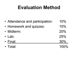
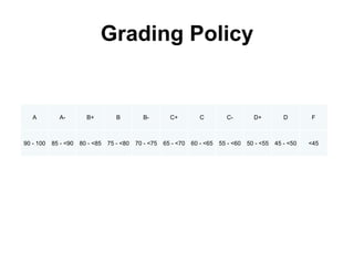
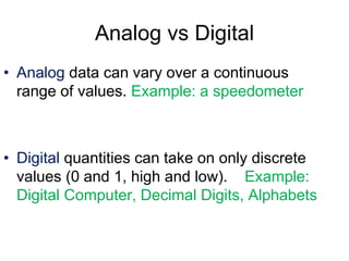
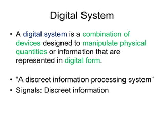
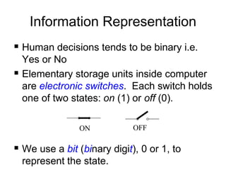
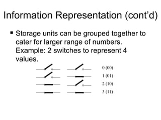
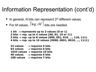
CSE 204
Digital Logic Design
Lecture 01
Dr. Tarem Ahmed
Course Information
Class Timings
• Theory: ST, 13:40~15:10
• Lab: R, 13:40~15:10
• Office Hours: Before/after class, and by
appointment
Evaluation Method
• Attendance and participation: 10%
• Homework and quizzes: 15%
• Midterm: 20%
• Lab: 25%
• Final: 30%_
• Total: 100%
HW and Quizzes
• Weekly HW and Quizzes
• All quizzes will count, total will be
scaled by highest aggregate
Textbook
• Textbook:
• Mano and Kime, Logic and Computer Design
Fundamentals, 5th Edition Updated, Addison-Wesley
• Reference book:
• Katz, Contemporary Logic Design,
Benjamin/Cummings.
• Reading required!!!
Grading Policy
A A- B+ B B- C+ C C- D+ D F
90 - 100 85 - <90 80 - <85 75 - <80 70 - <75 65 - <70 60 - <65 55 - <60 50 - <55 45 - <50 <45
Piazza Link
• IUB
• Summer 2019
• Digital Logic Design
• CSE204-02
• Please register…
Let us begin…
Analog vs Digital
• Analog data can vary over a continuous
range of values. Example: a speedometer
• Digital quantities can take on only discrete
values (0 and 1, high and low). Example:
Digital Computer, Decimal Digits, Alphabets
Digital System
• A digital system is a combination of
devices designed to manipulate physical
quantities or information that are
represented in digital form.
• “A discreet information processing system”
• Signals: Discreet information
Limitations of Digital
Technology
• The real world is analog!
• Human senses are analog!
Overcoming the Limitations
• Convert the real world analog input data
into digital one
• Process this digital data
• Then again convert back into analog form
Advantages of a Digital System
• Better noise immunity
• Transmission error detection and
correction possible
• Easier information storage
• Data Compression possible
• Data Encryption possible
• Programmability (instructions)
• Hardware cheaper to produce
Digital Logic
• Design logic is a term used to denote the
design and analysis of digital systems
• Digital logic is concerned with the
interconnection among digital components
and modules
• Digital logic design is engineering and
engineering means problem solving
Number Systems and Codes
Digital Systems are built from circuits that
process binary digits. BUT very few real-
life problems are based on binary
numbers.
SO a digital system designer must
establish some correspondence between
the binary digits processed by digital
circuits and real-life numbers, events and
conditions.
Morse Code
• First example of a digital system…
Information Representation
 Human decisions tends to be binary i.e.
Yes or No
 Elementary storage units inside computer
are electronic switches. Each switch holds
one of two states: on (1) or off (0).
 We use a bit (binary digit), 0 or 1, to
represent the state.
ON OFF
Information Representation (cont’d)
 Storage units can be grouped together to
cater for larger range of numbers.
Example: 2 switches to represent 4
values.
0 (00)
1 (01)
2 (10)
3 (11)
Information Representation (cont’d)
 In general, N bits can represent 2N different values.
 For M values, bits are needed.
 
M
2
log
1 bit  represents up to 2 values (0 or 1)
2 bits  rep. up to 4 values (00, 01, 10 or 11)
3 bits  rep. up to 8 values (000, 001, 010. …, 110, 111)
4 bits  rep. up to 16 values (0000, 0001, 0010, …, 1111)
32 values  requires 5 bits
64 values  requires 6 bits
1024 values  requires 10 bits
40 values  requires 6 bits
100 values  requires 7 bits
Notes
• Reading
– Lesson Plan
– Mano and Kime, Ch 1-1

Lecture01_CSC 204_DIGUTAL LOGIC DESIGN_IUB.pptx

  • 1.
    CSE 204 Digital LogicDesign Lecture 01 Dr. Tarem Ahmed
  • 2.
  • 3.
    Class Timings • Theory:ST, 13:40~15:10 • Lab: R, 13:40~15:10 • Office Hours: Before/after class, and by appointment
  • 4.
    Evaluation Method • Attendanceand participation: 10% • Homework and quizzes: 15% • Midterm: 20% • Lab: 25% • Final: 30%_ • Total: 100%
  • 5.
    HW and Quizzes •Weekly HW and Quizzes • All quizzes will count, total will be scaled by highest aggregate
  • 6.
    Textbook • Textbook: • Manoand Kime, Logic and Computer Design Fundamentals, 5th Edition Updated, Addison-Wesley • Reference book: • Katz, Contemporary Logic Design, Benjamin/Cummings. • Reading required!!!
  • 7.
    Grading Policy A A-B+ B B- C+ C C- D+ D F 90 - 100 85 - <90 80 - <85 75 - <80 70 - <75 65 - <70 60 - <65 55 - <60 50 - <55 45 - <50 <45
  • 8.
    Piazza Link • IUB •Summer 2019 • Digital Logic Design • CSE204-02 • Please register…
  • 9.
  • 10.
    Analog vs Digital •Analog data can vary over a continuous range of values. Example: a speedometer • Digital quantities can take on only discrete values (0 and 1, high and low). Example: Digital Computer, Decimal Digits, Alphabets
  • 11.
    Digital System • Adigital system is a combination of devices designed to manipulate physical quantities or information that are represented in digital form. • “A discreet information processing system” • Signals: Discreet information
  • 12.
    Limitations of Digital Technology •The real world is analog! • Human senses are analog!
  • 13.
    Overcoming the Limitations •Convert the real world analog input data into digital one • Process this digital data • Then again convert back into analog form
  • 14.
    Advantages of aDigital System • Better noise immunity • Transmission error detection and correction possible • Easier information storage • Data Compression possible • Data Encryption possible • Programmability (instructions) • Hardware cheaper to produce
  • 15.
    Digital Logic • Designlogic is a term used to denote the design and analysis of digital systems • Digital logic is concerned with the interconnection among digital components and modules • Digital logic design is engineering and engineering means problem solving
  • 16.
    Number Systems andCodes Digital Systems are built from circuits that process binary digits. BUT very few real- life problems are based on binary numbers. SO a digital system designer must establish some correspondence between the binary digits processed by digital circuits and real-life numbers, events and conditions.
  • 17.
    Morse Code • Firstexample of a digital system…
  • 18.
    Information Representation  Humandecisions tends to be binary i.e. Yes or No  Elementary storage units inside computer are electronic switches. Each switch holds one of two states: on (1) or off (0).  We use a bit (binary digit), 0 or 1, to represent the state. ON OFF
  • 19.
    Information Representation (cont’d) Storage units can be grouped together to cater for larger range of numbers. Example: 2 switches to represent 4 values. 0 (00) 1 (01) 2 (10) 3 (11)
  • 20.
    Information Representation (cont’d) In general, N bits can represent 2N different values.  For M values, bits are needed.   M 2 log 1 bit  represents up to 2 values (0 or 1) 2 bits  rep. up to 4 values (00, 01, 10 or 11) 3 bits  rep. up to 8 values (000, 001, 010. …, 110, 111) 4 bits  rep. up to 16 values (0000, 0001, 0010, …, 1111) 32 values  requires 5 bits 64 values  requires 6 bits 1024 values  requires 10 bits 40 values  requires 6 bits 100 values  requires 7 bits
  • 21.
    Notes • Reading – LessonPlan – Mano and Kime, Ch 1-1