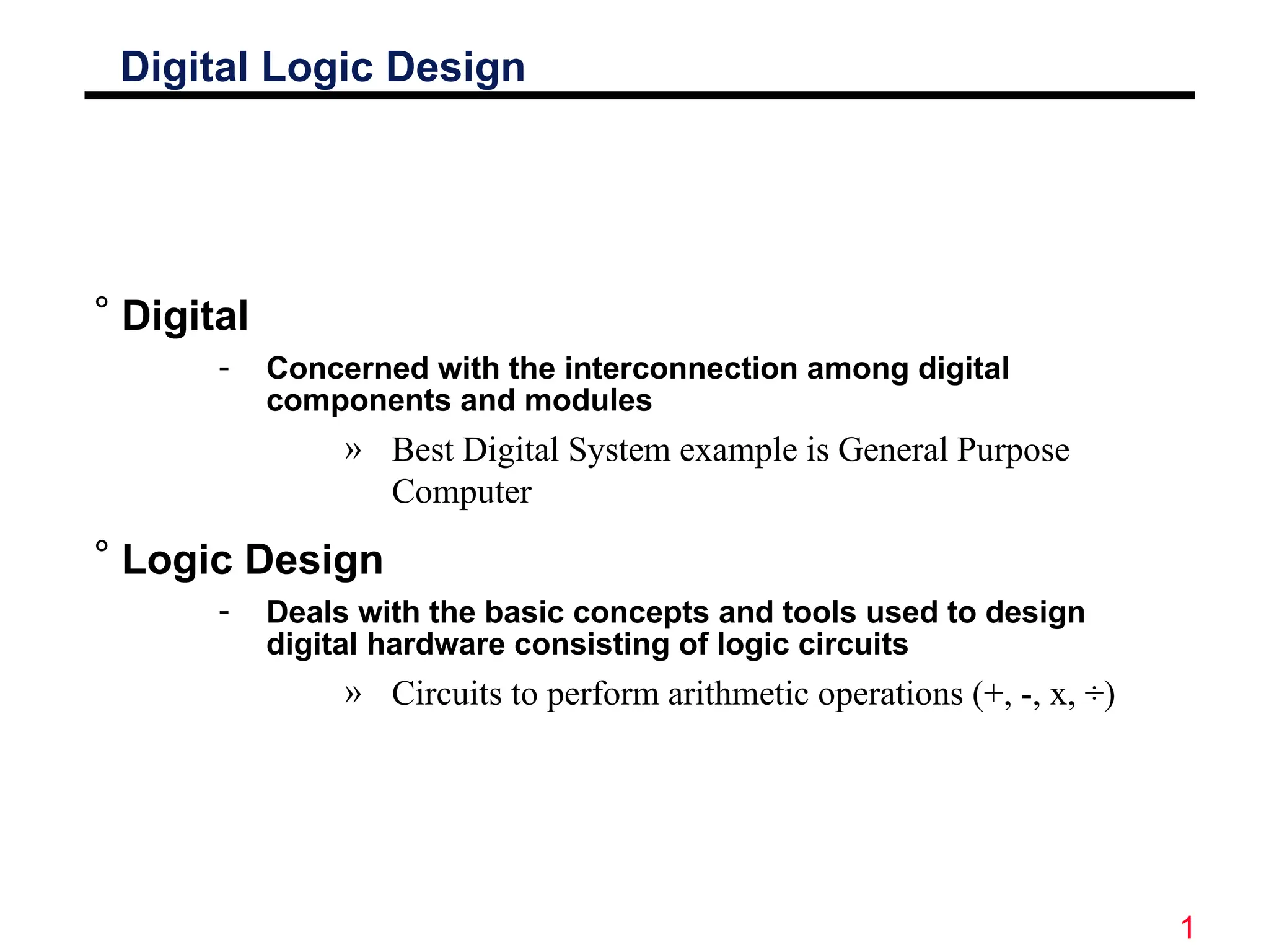
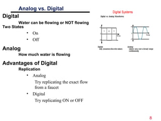
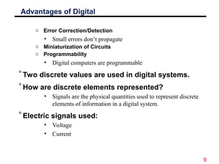
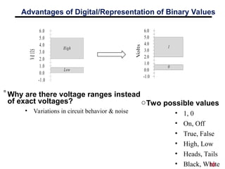
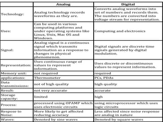
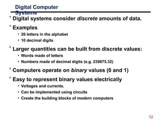
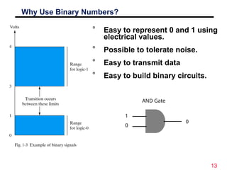
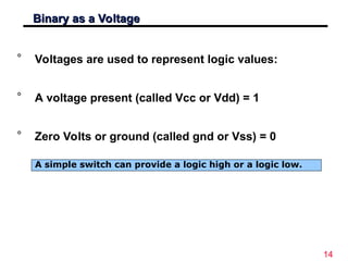
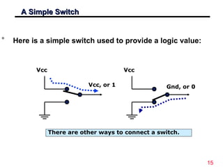
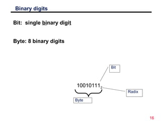
1
Digital Logic Design
° Digital
- Concerned with the interconnection among digital
components and modules
» Best Digital System example is General Purpose
Computer
° Logic Design
- Deals with the basic concepts and tools used to design
digital hardware consisting of logic circuits
» Circuits to perform arithmetic operations (+, -, x, ÷)
2
Digi
Digi
tal
tal
Sig
Sig
nals
nals
° Decimal values are difficult to represent in electrical
systems. It is easier to use two voltage values than
ten.
° Digital Signals have two basic states:
1 (logic “high”, or H, or “on”)
0 (logic “low”, or L, or “off”)
° Digital values are in a binary format. Binary means
2 states.
° A good example of binary is a light (only on or off)
on off
Power switches have labels “1” for on and “0” for off.
3
Motivation
° Microprocessors/Microelectronics have
revolutionized our world
• Cell phones, internet, rapid advances in medicine, etc.
° The semiconductor industry has grown tremendously
4
Text Book
° Primary Text:
“Digital Design” By M. Morris Mano and Michael D.
Ciletti
° Complementary Material
“Logic and Computer Design Fundamentals” By M.
Morris Mano & Charles R Kime.
5
Digital Logic Design
Lecture 1
Number Systems
6
Number Systems
° Decimal is the number system that we use
° Binary is a number system that computers use
° Octal is a number system that represents groups of
binary numbers (binary shorthand).
° Hexadecimal (Hex) is a number system that
represents groups of binary numbers (binary
shorthand). Hex is primarily used in computing as
the most common form of expressing a human-
readable string representation of a byte (group of 8
bits).
7
Overvie
w
° The design of computers
• It all starts with numbers
• Building circuits
• Building computing machines
° Digital systems
° Understanding decimal numbers
° Binary and octal numbers
• The basis of computers!
° Conversion between different number systems
8
Analog vs. Digital
Digital
Water can be flowing or NOT flowing
Two States
• On
• Off
Analog
How much water is flowing
Advantages of Digital
Replication
• Analog
Try replicating the exact flow
from a faucet
• Digital
Try replicating ON or OFF
9
Advantages of Digital
o Error Correction/Detection
• Small errors don’t propagate
o Miniaturization of Circuits
o Programmability
• Digital computers are programmable
°Two discrete values are used in digital systems.
°How are discrete elements represented?
• Signals are the physical quantities used to represent discrete
elements of information in a digital system.
°Electric signals used:
• Voltage
• Current
10
Advantages of Digital/Representation of Binary Values
Vo
lts
-1.0
0.0
1.0
2.0
3.0
4.0
5.0
6.0
High
Low
°Why are there voltage ranges instead
of exact voltages?
• Variations in circuit behavior & noise
oTwo possible values
• 1, 0
• On, Off
• True, False
• High, Low
• Heads, Tails
• Black, White
11
12
Digital Computer
Systems
° Digital systems consider discrete amounts of data.
° Examples
• 26 letters in the alphabet
• 10 decimal digits
° Larger quantities can be built from discrete values:
• Words made of letters
• Numbers made of decimal digits (e.g. 239875.32)
° Computers operate on binary values (0 and 1)
° Easy to represent binary values electrically
• Voltages and currents.
• Can be implemented using circuits
• Create the building blocks of modern computers
13
Why Use Binary Numbers?
° Easy to represent 0 and 1 using
electrical values.
° Possible to tolerate noise.
° Easy to transmit data
° Easy to build binary circuits.
AND Gate
1
0
0
14
Binary as a Voltage
Binary as a Voltage
° Voltages are used to represent logic values:
° A voltage present (called Vcc or Vdd) = 1
° Zero Volts or ground (called gnd or Vss) = 0
A simple switch can provide a logic high or a logic low.
15
A Simple Switch
A Simple Switch
° Here is a simple switch used to provide a logic value:
Vcc
Gnd, or 0
Vcc
Vcc, or 1
There are other ways to connect a switch.
16
Binary digits
Bit: single binary digit
Byte: 8 binary digits
100101112
Bit
Byte
Radix

Lecture 00 - Digital Logic Design Course.ppt

  • 1.
    1 Digital Logic Design °Digital - Concerned with the interconnection among digital components and modules » Best Digital System example is General Purpose Computer ° Logic Design - Deals with the basic concepts and tools used to design digital hardware consisting of logic circuits » Circuits to perform arithmetic operations (+, -, x, ÷)
  • 2.
    2 Digi Digi tal tal Sig Sig nals nals ° Decimal valuesare difficult to represent in electrical systems. It is easier to use two voltage values than ten. ° Digital Signals have two basic states: 1 (logic “high”, or H, or “on”) 0 (logic “low”, or L, or “off”) ° Digital values are in a binary format. Binary means 2 states. ° A good example of binary is a light (only on or off) on off Power switches have labels “1” for on and “0” for off.
  • 3.
    3 Motivation ° Microprocessors/Microelectronics have revolutionizedour world • Cell phones, internet, rapid advances in medicine, etc. ° The semiconductor industry has grown tremendously
  • 4.
    4 Text Book ° PrimaryText: “Digital Design” By M. Morris Mano and Michael D. Ciletti ° Complementary Material “Logic and Computer Design Fundamentals” By M. Morris Mano & Charles R Kime.
  • 5.
  • 6.
    6 Number Systems ° Decimalis the number system that we use ° Binary is a number system that computers use ° Octal is a number system that represents groups of binary numbers (binary shorthand). ° Hexadecimal (Hex) is a number system that represents groups of binary numbers (binary shorthand). Hex is primarily used in computing as the most common form of expressing a human- readable string representation of a byte (group of 8 bits).
  • 7.
    7 Overvie w ° The designof computers • It all starts with numbers • Building circuits • Building computing machines ° Digital systems ° Understanding decimal numbers ° Binary and octal numbers • The basis of computers! ° Conversion between different number systems
  • 8.
    8 Analog vs. Digital Digital Watercan be flowing or NOT flowing Two States • On • Off Analog How much water is flowing Advantages of Digital Replication • Analog Try replicating the exact flow from a faucet • Digital Try replicating ON or OFF
  • 9.
    9 Advantages of Digital oError Correction/Detection • Small errors don’t propagate o Miniaturization of Circuits o Programmability • Digital computers are programmable °Two discrete values are used in digital systems. °How are discrete elements represented? • Signals are the physical quantities used to represent discrete elements of information in a digital system. °Electric signals used: • Voltage • Current
  • 10.
    10 Advantages of Digital/Representationof Binary Values Vo lts -1.0 0.0 1.0 2.0 3.0 4.0 5.0 6.0 High Low °Why are there voltage ranges instead of exact voltages? • Variations in circuit behavior & noise oTwo possible values • 1, 0 • On, Off • True, False • High, Low • Heads, Tails • Black, White
  • 11.
  • 12.
    12 Digital Computer Systems ° Digitalsystems consider discrete amounts of data. ° Examples • 26 letters in the alphabet • 10 decimal digits ° Larger quantities can be built from discrete values: • Words made of letters • Numbers made of decimal digits (e.g. 239875.32) ° Computers operate on binary values (0 and 1) ° Easy to represent binary values electrically • Voltages and currents. • Can be implemented using circuits • Create the building blocks of modern computers
  • 13.
    13 Why Use BinaryNumbers? ° Easy to represent 0 and 1 using electrical values. ° Possible to tolerate noise. ° Easy to transmit data ° Easy to build binary circuits. AND Gate 1 0 0
  • 14.
    14 Binary as aVoltage Binary as a Voltage ° Voltages are used to represent logic values: ° A voltage present (called Vcc or Vdd) = 1 ° Zero Volts or ground (called gnd or Vss) = 0 A simple switch can provide a logic high or a logic low.
  • 15.
    15 A Simple Switch ASimple Switch ° Here is a simple switch used to provide a logic value: Vcc Gnd, or 0 Vcc Vcc, or 1 There are other ways to connect a switch.
  • 16.
    16 Binary digits Bit: singlebinary digit Byte: 8 binary digits 100101112 Bit Byte Radix

Editor's Notes

  • #5 Give qualifications of instructors: DAP teaching computer architecture at Berkeley since 1977 Co-athor of textbook used in class Best known for being one of pioneers of RISC currently author of article on future of microprocessors in SciAm Sept 1995 RY took 152 as student, TAed 152,instructor in 152 undergrad and grad work at Berkeley joined NextGen to design fact 80x86 microprocessors one of architects of UltraSPARC fastest SPARC mper shipping this Fall
  • #7 credential: bring a computer die photo wafer : This can be an hidden slide. I just want to use this to do my own planning. I have rearranged Culler’s lecture slides slightly and add more slides. This covers everything he covers in his first lecture (and more) but may We will save the fun part, “ Levels of Organization,” at the end (so student can stay awake): I will show the internal stricture of the SS10/20. Notes to Patterson: You may want to edit the slides in your section or add extra slides to taylor your needs.
  • #12 credential: bring a computer die photo wafer : This can be an hidden slide. I just want to use this to do my own planning. I have rearranged Culler’s lecture slides slightly and add more slides. This covers everything he covers in his first lecture (and more) but may We will save the fun part, “ Levels of Organization,” at the end (so student can stay awake): I will show the internal stricture of the SS10/20. Notes to Patterson: You may want to edit the slides in your section or add extra slides to taylor your needs.