The Instruction
Cycle
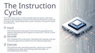
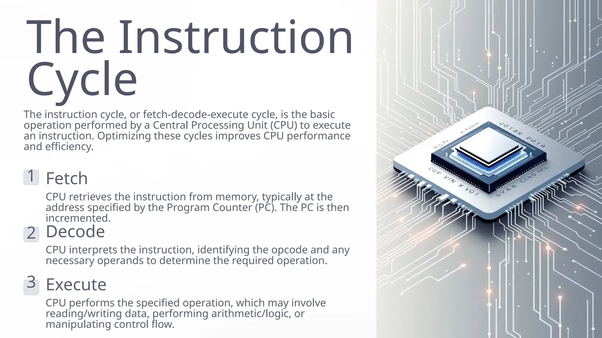
The instructioncycle, or fetch-decode-execute cycle, is the basic
operation performed by a Central Processing Unit (CPU) to execute
an instruction. Optimizing these cycles improves CPU performance
and efficiency.
1 Fetch
CPU retrieves the instruction from memory, typically at the
address specified by the Program Counter (PC). The PC is then
incremented.
2 Decode
CPU interprets the instruction, identifying the opcode and any
necessary operands to determine the required operation.
3 Execute
CPU performs the specified operation, which may involve
reading/writing data, performing arithmetic/logic, or
manipulating control flow.
2.
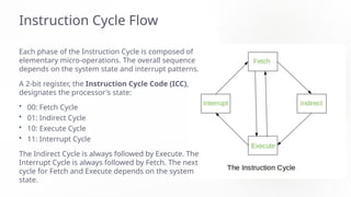
Instruction Cycle Flow
Eachphase of the Instruction Cycle is composed of
elementary micro-operations. The overall sequence
depends on the system state and interrupt patterns.
A 2-bit register, the Instruction Cycle Code (ICC),
designates the processor's state:
• 00: Fetch Cycle
• 01: Indirect Cycle
• 10: Execute Cycle
• 11: Interrupt Cycle
The Indirect Cycle is always followed by Execute. The
Interrupt Cycle is always followed by Fetch. The next
cycle for Fetch and Execute depends on the system
state.
3.
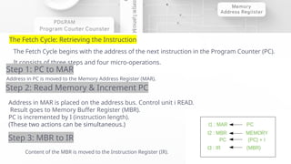
The Fetch Cycle:Retrieving the Instruction
The Fetch Cycle begins with the address of the next instruction in the Program Counter (PC).
It consists of three steps and four micro-operations.
Step 1: PC to MAR
Address in PC is moved to the Memory Address Register (MAR).
Step 2: Read Memory & Increment PC
Address in MAR is placed on the address bus. Control unit i READ.
Result goes to Memory Buffer Register (MBR).
PC is incremented by I (instruction length).
(These two actions can be simultaneous.)
Step 3: MBR to IR
Content of the MBR is moved to the Instruction Register (IR).
Symbolic Sequence:
4.
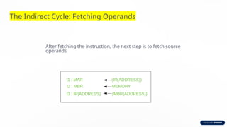
The Indirect Cycle:Fetching Operands
After fetching the instruction, the next step is to fetch source
operands
5.
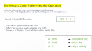
The Execute Cycle:Performing the Operation
Unlike the other simple cycles, the Execute Cycle is highly variable.
For a machine with N opcodes, there are N different sequences of micro-operations.
Example 1: Simple ADD Instruction
• IR's address portion loads into MAR.
• Reference memory location is read into MBR.
• Contents of Register R and MBR are added by the ALU.
6.
The Interrupt Cycle:Handling External Signals
This cycle occurs after the Execute Cycle if an enabled interrupt has occurred.
Its nature varies by machine, but the goal is to save the current state and
jump to the interrupt routine.
7.
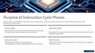
Purpose of InstructionCycle Phases
Each cycle is essential for the processor's operation, ensuring instructions are understood, executed, and
results are preserved.
Fetch Cycle
Retrieves the instruction from memory, informing
the processor what needs to be executed.
Decode Cycle
Interprets the instruction to determine the operation and
required operands.
Execute Cycle
Performs the actual computation or
manipulation of data specified by the instruction.
Store Cycle
Saves the result of the operation in memory or a register
for future use.
8.
The Evolution of
ProgrammingLanguages
A look at the foundational differences between Machine Language and
Assembly Language, and how they shaped computing.
9.
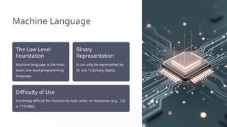
Machine Language
The Low-Level
Foundation
Machinelanguage is the most
basic, low-level programming
language.
Binary
Representation
It can only be represented by
0s and 1s (binary digits).
Difficulty of Use
Extremely difficult for humans to read, write, or memorize (e.g., 120
is 1111000).
10.
The Challenge ofBinary
In early computing, creating visuals or showing data was complex
using only 0s and 1s. This difficulty led to the invention of Assembly
Language.
11.
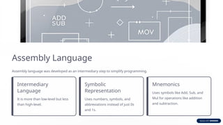
Assembly Language
Assembly languagewas developed as an intermediary step to simplify programming.
Intermediary
Language
It is more than low-level but less
than high-level.
Symbolic
Representation
Uses numbers, symbols, and
abbreviations instead of just 0s
and 1s.
Mnemonics
Uses symbols like Add, Sub, and
Mul for operations like addition
and subtraction.
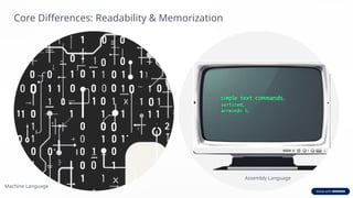
12.
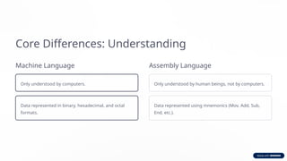
Core Differences: Understanding
MachineLanguage
Only understood by computers.
Data represented in binary, hexadecimal, and octal
formats.
Assembly Language
Only understood by human beings, not by computers.
Data represented using mnemonics (Mov, Add, Sub,
End, etc.).
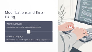
Modifications and Error
Fixing
MachineLanguage
Modifications and error fixing cannot be done easily.
Assembly Language
Modifications and error fixing can be done easily by programmers.
15.
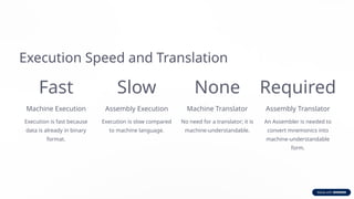
Execution Speed andTranslation
Fast
Machine Execution
Execution is fast because
data is already in binary
format.
Slow
Assembly Execution
Execution is slow compared
to machine language.
None
Machine Translator
No need for a translator; it is
machine-understandable.
Required
Assembly Translator
An Assembler is needed to
convert mnemonics into
machine-understandable
form.
16.
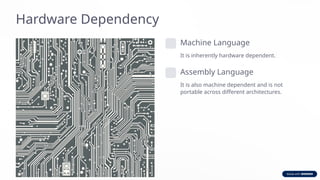
Hardware Dependency
Machine Language
Itis inherently hardware dependent.
Assembly Language
It is also machine dependent and is not
portable across different architectures.