The document is a comprehensive guide on Fluid Mechanics and Hydraulic Machinery for B.Tech students in the Mechanical Engineering department at Malla Reddy College of Engineering & Technology. It covers essential topics such as fluid statics, fluid dynamics, boundary layers, turbomachinery, and pump operations, alongside objectives, outcomes, and measurement techniques. The document also provides references and outlines the fundamentals, properties, and behavior of fluids, including viscosity, surface tension, and types of fluids.
![17 Department of Mechanical Engineering, MRCET
p + 900 × 9.81 × 0.08 = 13.6 × 1000 × 9.81 × 0.2
p = 13.6 × 1000 × 9.81 × 0.2 – 900 × 9.81 × 0.08
p = 26683 – 706
p = 25977 N/m2
p = 2.597 N/cm2
Pressure of fluid = 2.597 N/ cm2
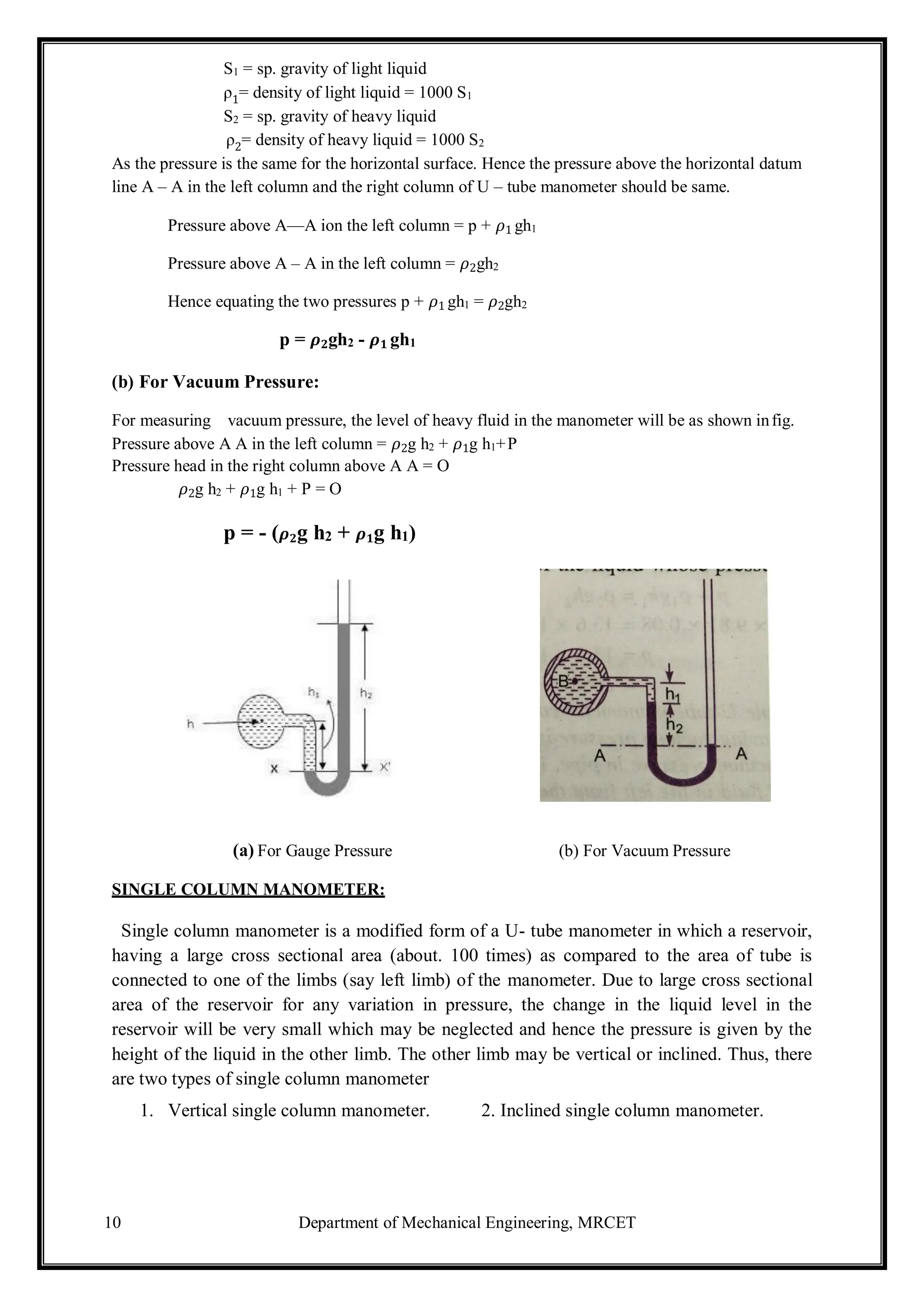
6. A simple U – tube manometer containing mercury is connected to a pipe in which a fluid of sp.gr.
0.8 And having vacuum pressure is flowing. The other end of the manometer is open to atmosphere.
Find the vacuum pressure in pipe, if the difference of mercury level in the two limbs is 40cm. and the
height of the fluid in the left tube from the centre of pipe is 15cm below.
Given,
Sp.gr of fluid S1 = 0.8
Sp.gr. of mercury S2 = 13.6
Density of the fluid = S1 × 1000 = 0.8 × 1000 = 800
Density of mercury = 13.6 × 1000
Difference of mercury level h2 = 40cm = 0.4m
Height of the liquid in the left limb = 15cm =0.15m
Let the pressure in the pipe = p
Equating pressures above datum line A-- A
𝜌2gh2 + 𝜌1gh1 + P = 0
P = - [𝜌2gh2 + 𝜌1gh1]
= - [13.6 ×1000 × 9.81 × 0.4 + 800 × 9.81 × 0.15]
= 53366.4 + 1177.2
= -54543.6 N/m2
P = - 5.454 N/cm2
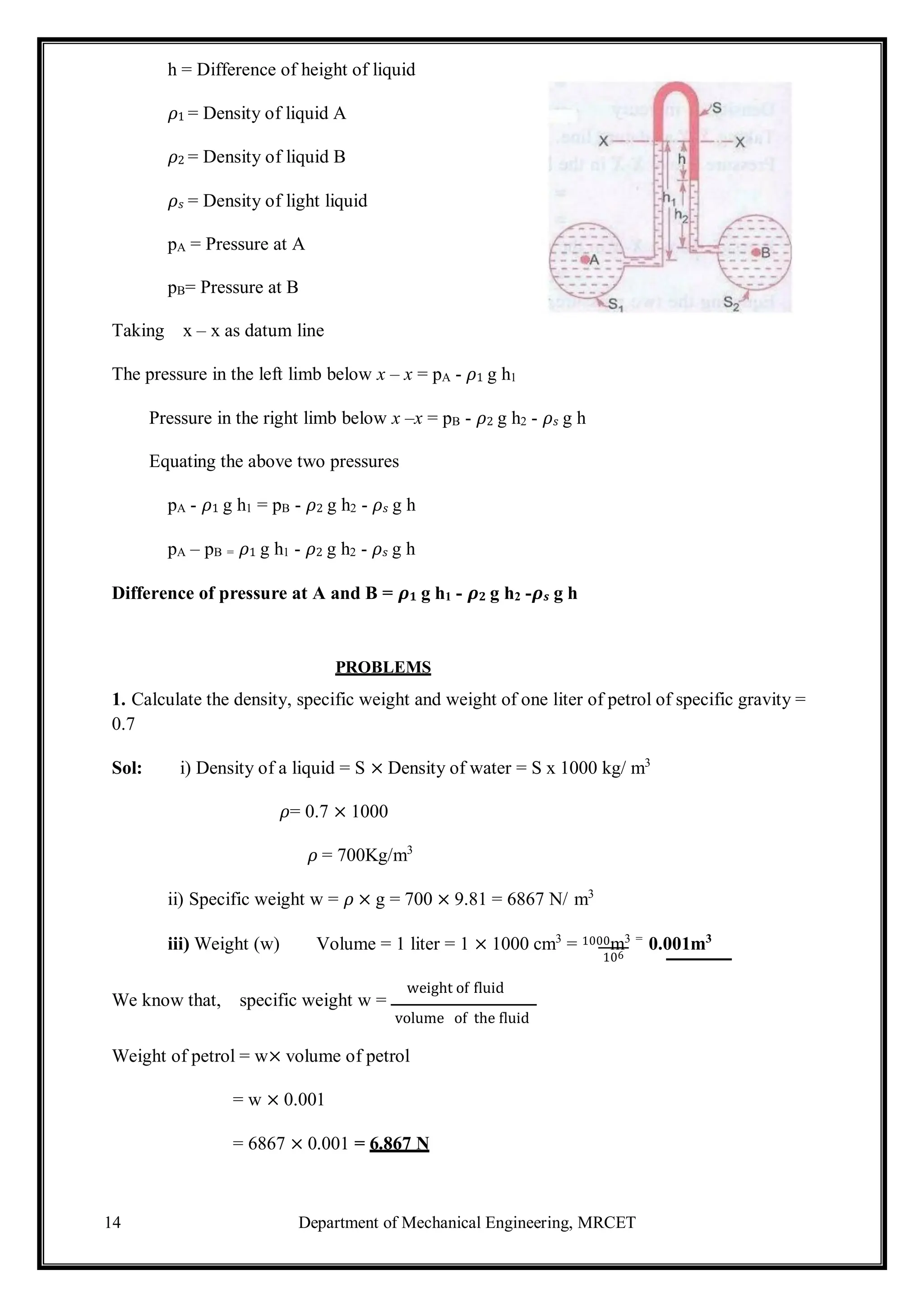
7. What are the gauge pressure and absolute pressure at a point 3m below the surface of a liquid
having a density of 1.53 x 10³
kg/m3
? If the atmospheric pressure is equivalent to 750mm of mercury.
The specific gravity of mercury is 13.6 and density of water 1000 kg/m3
Given:
Depth of the liquid, z1 = 3m
Density of liquid 𝜌1= 1.53 × 10³
kg/ m3
Atmospheric pressure head z0 = 750 mm of mercury = 750
1000
= 0.75m of Hg
Atmospheric pressure patm = 𝜌0 × g × z0
Where 𝜌0 = density of Hg = sp.gr. of mercury x density of water
= 13.6 × 1000 kg/ m3
And z0 = pressure head in terms of mercury = 0.75m of Hg
Patm = (13.6 × 1000) × 9.81 × 0.75 N/m2
= 100062 N/ m2
Pressure at a point, which is at a depth of 3m from the free surface of the liquid is
P = 𝜌1 × g × z1 =1.53× 103
× 9.81 × 3
Gauge pressure P = 45028 N/ m2](https://image.slidesharecdn.com/fluidmechanics-241105055638-83e87bce/75/lecture-notes-on-fundamental-of-mechanical-engineering-20-2048.jpg)
![18 Department of Mechanical Engineering, MRCET
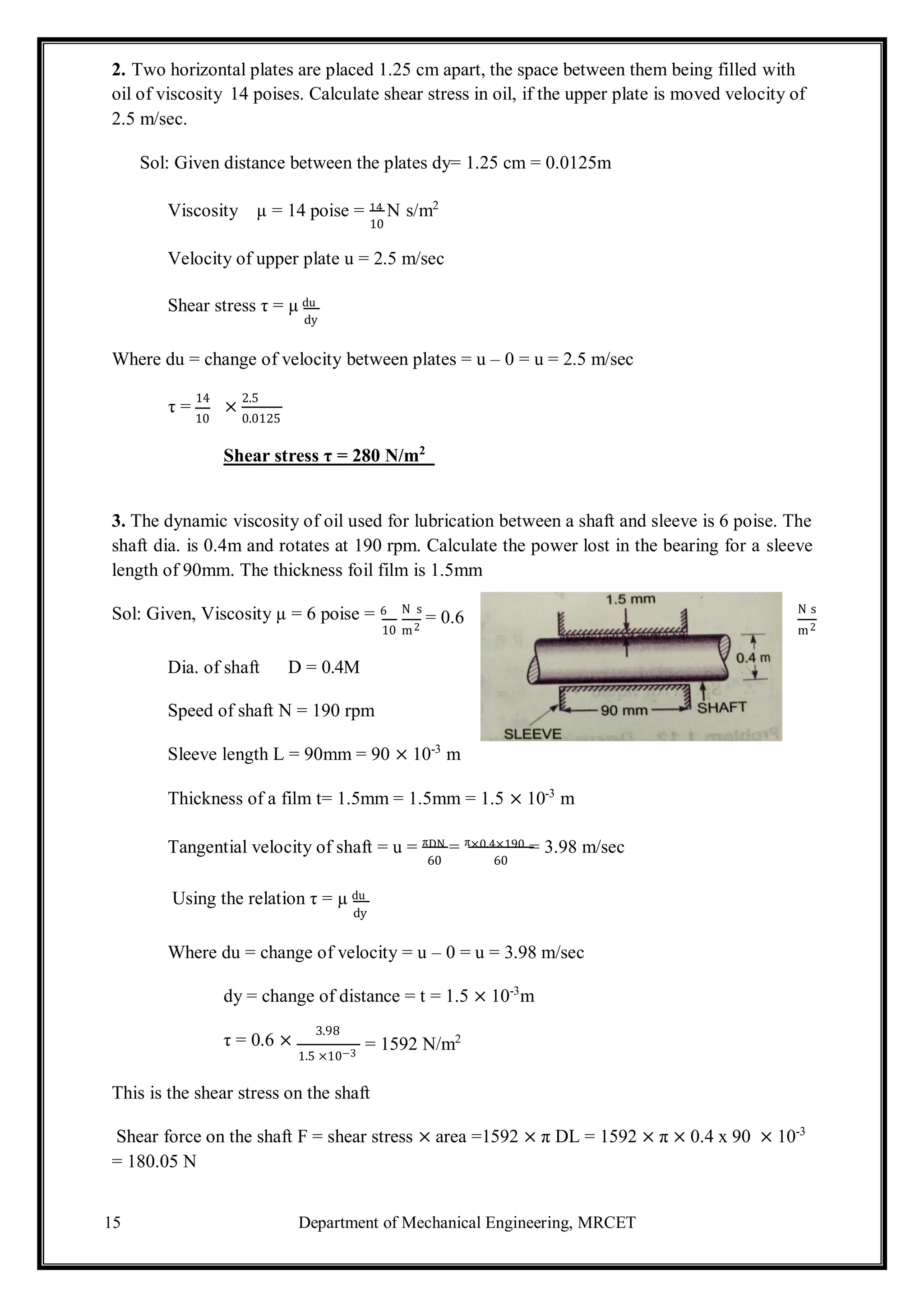
Absolute Pressure = Gauge pressure + Atmospheric pressure
= 45028 + 100062
Absolute Pressure = 145090 N/m2
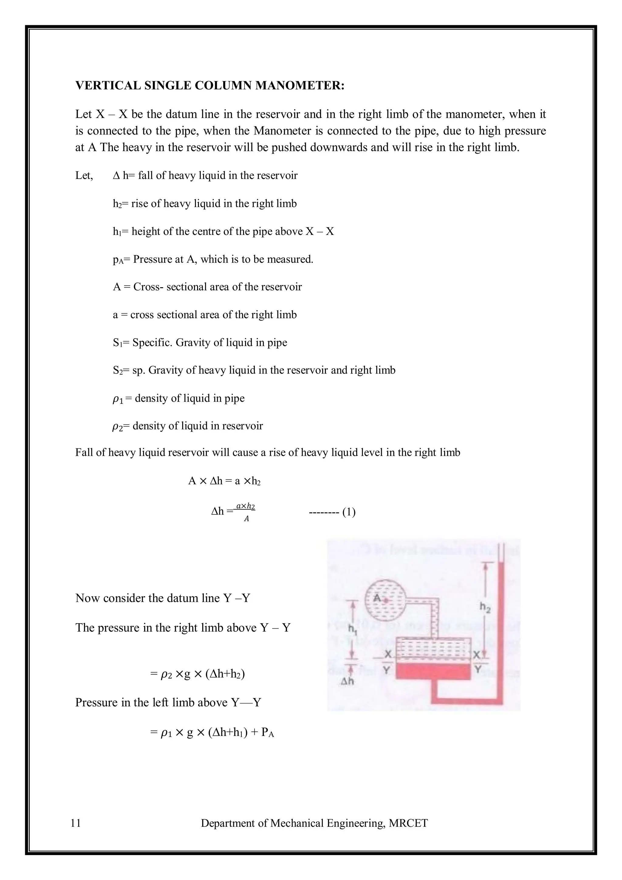
8. A single column manometer is connected to the pipe containing liquid of sp.gr.0.9. Find the
pressure in the pipe if the area of the reservoir is 100 times the area of the tube of manometer. sp.gr.
of mercury is 13.6. Height of the liquid from the centre of pipe is 20cm and difference in level of
mercury is 40cm.
Given,
Sp.gr. of liquid in pipe S1 = 0.9
Density 𝜌1= 900 kg/ m3
Sp.gr. of heavy liquid S2 = 13.6
Density 𝜌2= 13600
Area of reservoir
Area of right limb
=
A
= 100
a
Height of the liquid h1 = 20cm = 0.2m
Rise of mercury in the right limb h2 = 40cm = 0.4m
Pressure in pipe A
p = A × h [𝜌 g - 𝜌 g] h 𝜌 g - h 𝜌 g
A a 2 2 1 + 2 2 1 1
=
1
100
× 0.4 [13600 × 9.81 – 900 x 9.81] + 0.4 × 13600 × 9.81 – 0.2 × 900 × 9.81
= 0.4 [133416 – 8829] + 53366.4 – 1765.8
100
= 533.664 + 53366.4 – 1765.8
= 52134 N/m2
Pressure in pipe A= 5.21 N/ cm2
9. A pipe contains an oil of sp.gr.0.9. A differential manometer is connected at the two points A and
B shows a difference in mercury level at 15cm. find the difference of pressure at the two points.
Given: Sp.gr. of oil S1 = 0.9: density 𝜌1= 0.9 x 1000 = 900 kg/ m3
Difference of level in the mercury h = 15cm = 0.15 m
Sp.gr. of mercury = 13.6, Density = 13.6 × 1000 = 13600 kg/m3
The difference of pressure pA – pB = g × h × (𝜌𝑔 - 𝜌1)
= 9.81 x 0.15 (13600 – 900)
pA – pB = 18688 N/ m2
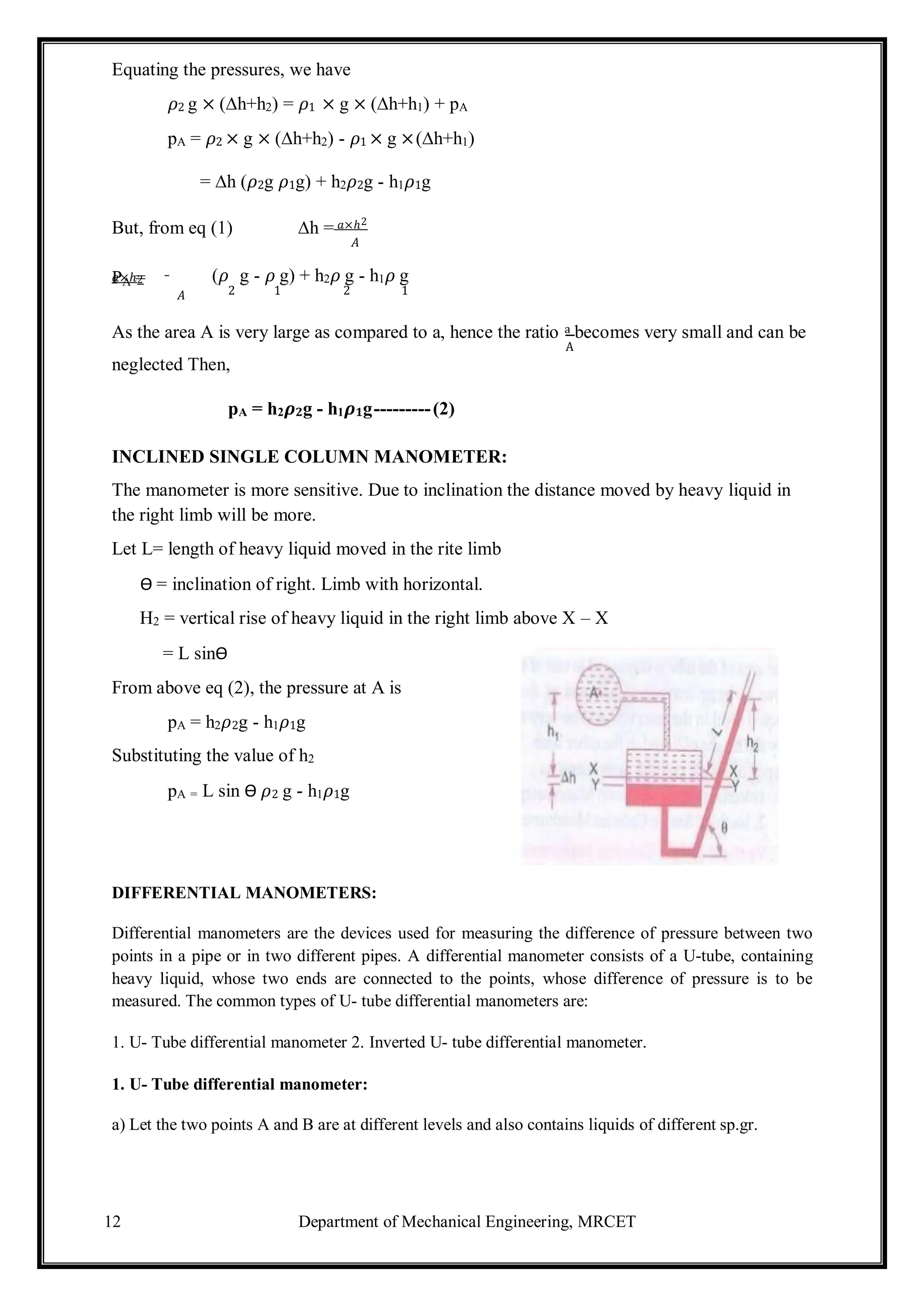
10. A differential manometer is connected at two points A and B .At B
air pressure is 9.81 N/cm2
. Find absolute pressure at A.
Density of air = 0.9 × 1000 = 900 kg/m3
Density of mercury = 13.6 × 10³
kg/ m3](https://image.slidesharecdn.com/fluidmechanics-241105055638-83e87bce/75/lecture-notes-on-fundamental-of-mechanical-engineering-21-2048.jpg)
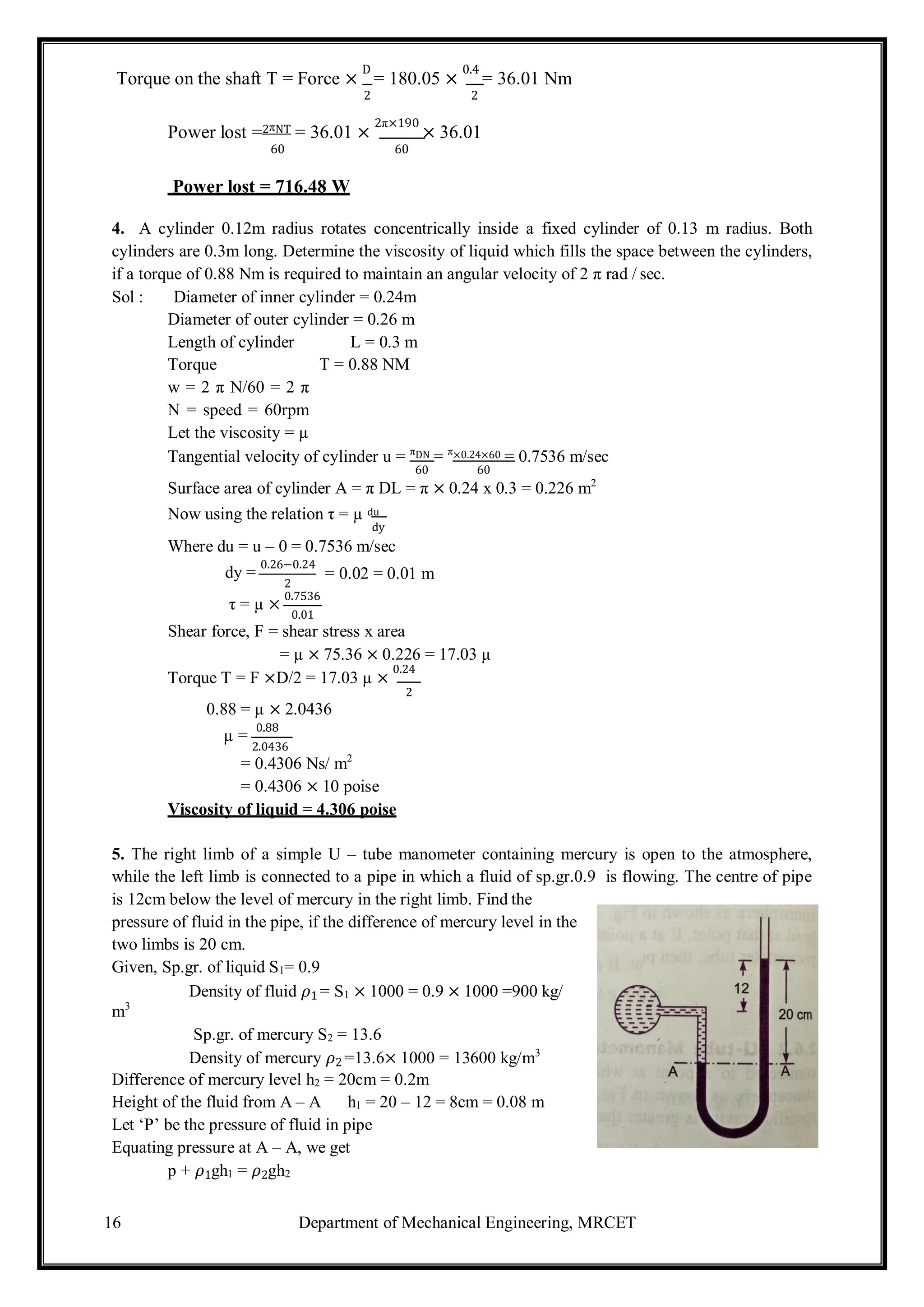
![20 Department of Mechanical Engineering, MRCET
Sp.gr. of liquid at B S2 == 0.9
Pressure at A pA= 1 kgf/c m2
= 1 × 10⁴
× kg/m2
= 1 × 104
× 9.81N/m2
Pressure at B pB = 1.8 kgf/cm2 =
1.8 × 104
× 9.81 N/m2
[1kgf = 9.81 N]
Density of mercury = 13.6 × 1000 kg/m3
Taking X – X as datum line
Pressure above X – X in left limb
= 13.6 × 1000 × 9.81 × h + 1500 × 9.81(2+3) + (9.81 x 10⁴
)
Pressure above X – X in the right limb = 900 × 9.81(h + 2) + 1.8 × 9.81 × 104
Equating the two pressures, we get
13.6 × 1000 × 9.81h + 1500 × 9.81 × 5 + 9.81 × 104
= 900 × 9.81(h + 2) + 1.8 × 9.81 × 104
Dividing both sides by 1000 × 9.81
13.6 h + 7.5 +10 = 0.9(h+2) + 18
(13.6 – 0.9)h = 1.8 + 18 – 17.5 = 19.8 – 17.5 =2.3
h =
2.3
12.7
= 0.181m
h = 18.1 cm](https://image.slidesharecdn.com/fluidmechanics-241105055638-83e87bce/75/lecture-notes-on-fundamental-of-mechanical-engineering-23-2048.jpg)
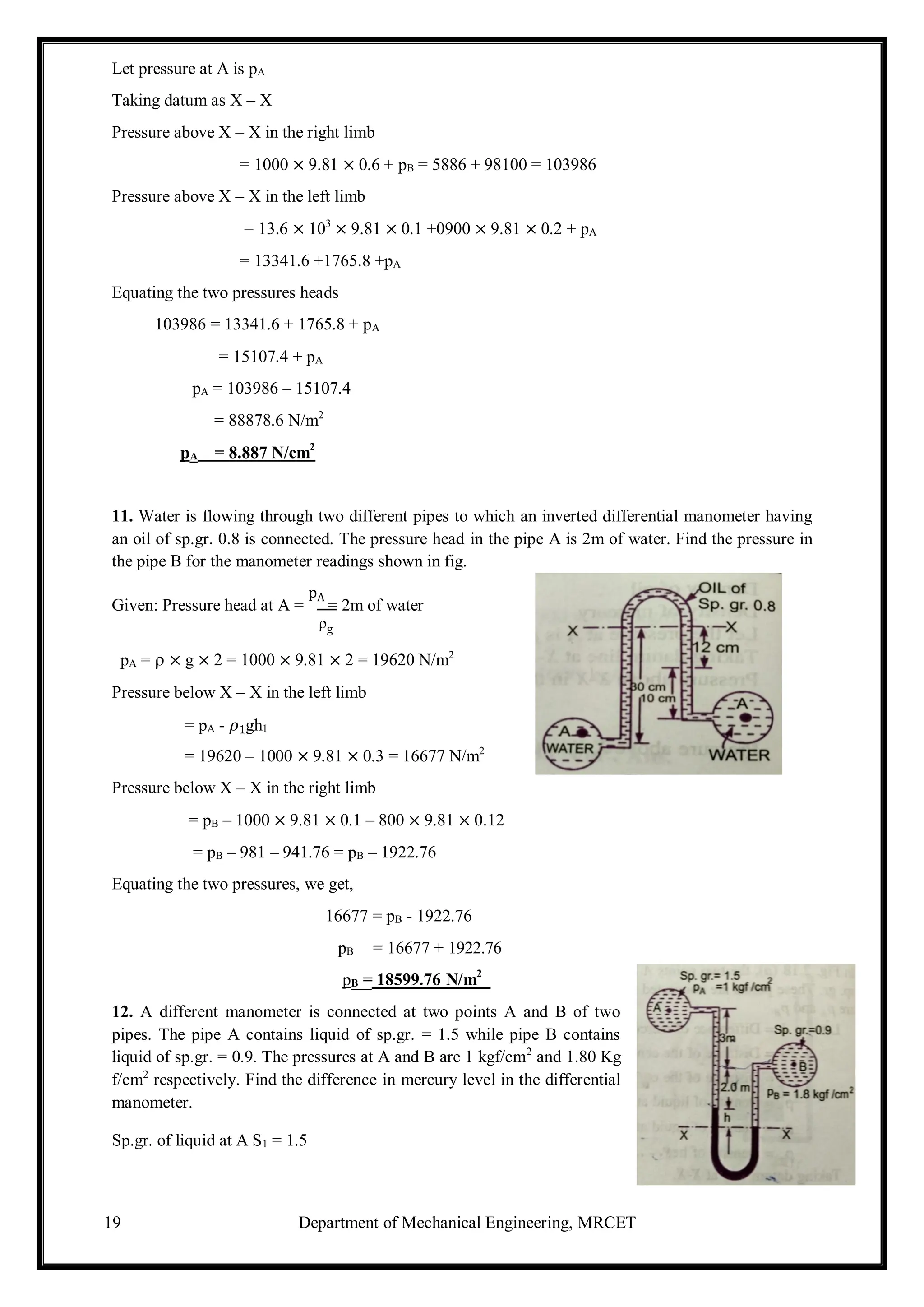
![Department of Mechanical Engineering, MRCET
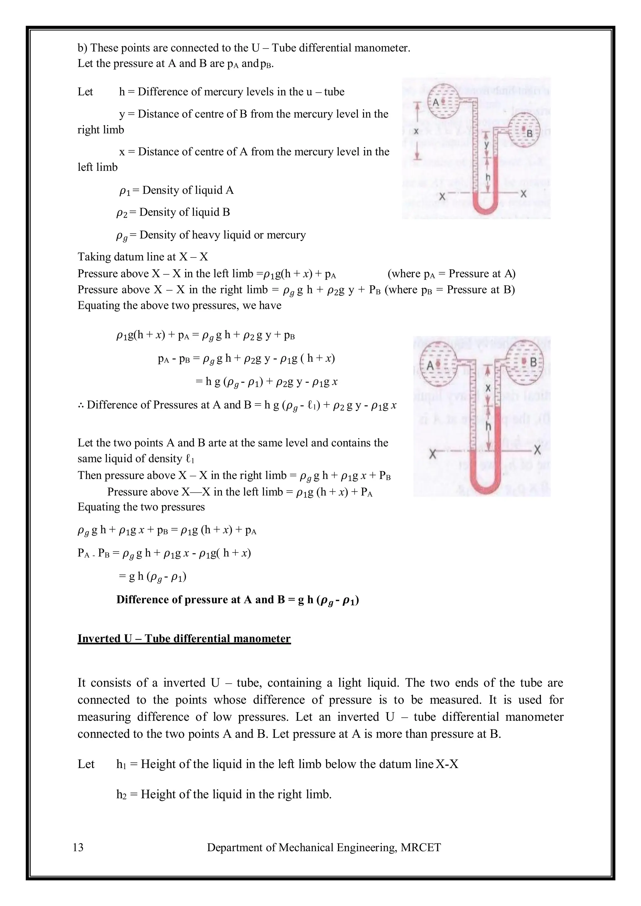
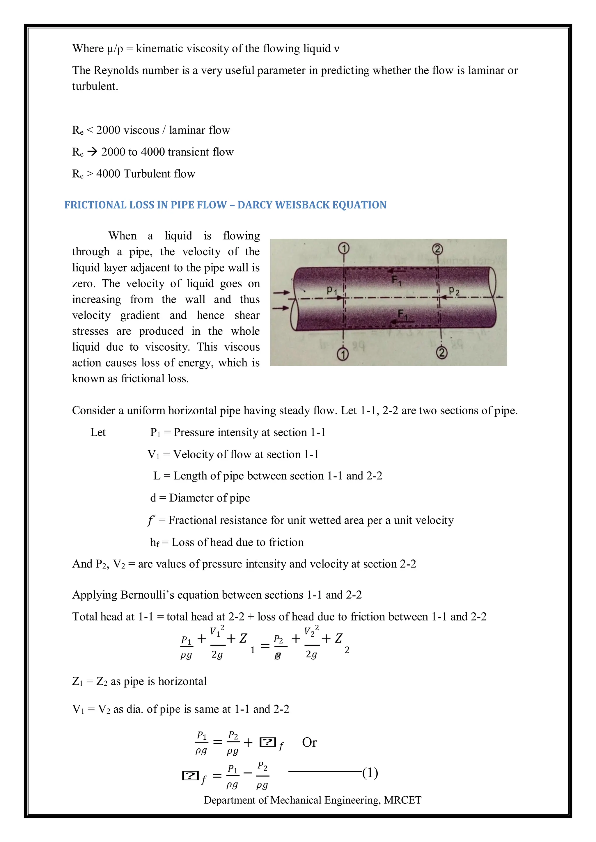
But hf is head is lost due to friction and hence the intensity of pressure will be reduced in the
direction flow by frictional resistance.
Now, Frictional Resistance = Frictional resistance per unit wetted area per unit velocity
× Wetted Area × (velocity)2
𝐹1 = 𝑓′ × 𝜋𝑑𝐿× 𝑉2 [∵Wetted area =𝜋𝑑 × 𝐿, Velocity = V=V1=V2 ]
𝐹1 = 𝑓′ × 𝑝𝐿𝑉2 (2) [∵ 𝜋d = perimeter = p ]
The forces acting on the fluid between section 1-1 and 2-2 are
Pressure force at section 1-1 = P1 ×A where A = area of pipe
Pressure force at section 2-2 = P2 ×A
Frictional force = F1
Resolving all forces in the horizontal direction, we have
P1 A – P2A – F1 = 0
(P1 – P2)A = F1 = 𝑓′ × 𝑝 × 𝐿 × 𝑉2 from equation – (2)
P1 – P2 =
𝑓′ ×𝑝×𝐿×𝑉2
A
But from equation (1) P1 - P2 = ρghf
Equating the value of P1 - P2, we get
ρghf =
𝑓′ ×𝑝×𝐿×𝑉2
A
𝑓 =
f′
pg
×
P
× L × V2 (3)
A
In the equation (3)
P
A
=
Wetted Permiter
Area
πd π
π
d2
=
d
4
=
𝑓′ 4
2 𝑓′ 4𝐿𝑉2
× × 𝐿 × 𝑉
𝜌𝑔 𝑑
= ×
𝜌𝑔 𝑑
Putting
𝑓′
𝜌
=
𝑓
2
Where f is known as co-efficient of friction.
=
𝑓](https://image.slidesharecdn.com/fluidmechanics-241105055638-83e87bce/75/lecture-notes-on-fundamental-of-mechanical-engineering-45-2048.jpg)
![Department of Mechanical Engineering, MRCET
3. Water is flowing through a horizontal pipe of diameter 200mm at a velocity of 3m/sec. A
circular solid plate of diameter150mm is placed in the pipe to obstruct the flow. Find the loss
of head due to obstruction in the pipe, if CC =0.62.
Given: Diameter of pipe D = 200mm = 0.2m
Velocity V = 3m/sec
Area of pipe A = 𝜋 D2
= 𝜋 (0.2)2
= 0.03141m2
4 4
Diameter of obstruction d = 150mm =0.15m
Area of obstruction a = 𝜋 (0.15)2
=0.01767m
4
CC = 0.62
The head loss due to obstruction = 𝑉2
2
𝐴 2
− 1
2𝑔 −𝑎
=
3×3
2×9.81
0.03141
0.62× 0.03141 −0.01767
2
− 1
=
9
19.62
= 3.311m
[3.687 – 1]2
Problems on Pitot tube
1. A pitot tube is placed in the centre of a 300mm pipe line has one end pointing upstream
and other perpendicular to it. The mean velocity in the pipe is 0.80 of the central velocity.
Find the discharge through the pipe, if the pressure difference between the two orifices is
60mm of water. Co-efficient of Pitot tube CV =0.98
Given: Diameter of pipe = 300mm =0.3m
Difference of pressure head h = 60mm of water = 0.06m of water
Mean velocity 𝑉 = 0.80 × central velocity
Central velocity = 𝐶𝑣 2𝑔 = 0.98 × 2 × 9.81 × 0.06 = 1.063 𝑚/𝑠𝑒𝑐
Mean velocity =0.8 × 1.063 = 0.8504m/sec
Discharge Q = Area of pipe × Mean velocity = A × 𝑉
= 𝜋 (0.3)2
× 0.8504
4
= 0.06m3/sec](https://image.slidesharecdn.com/fluidmechanics-241105055638-83e87bce/75/lecture-notes-on-fundamental-of-mechanical-engineering-66-2048.jpg)
![Department of Mechanical Engineering, MRCET
= 𝜌 a V (Vsin 𝜃 – 0) = 𝜌 a V2
sin 𝜃----------------(1)
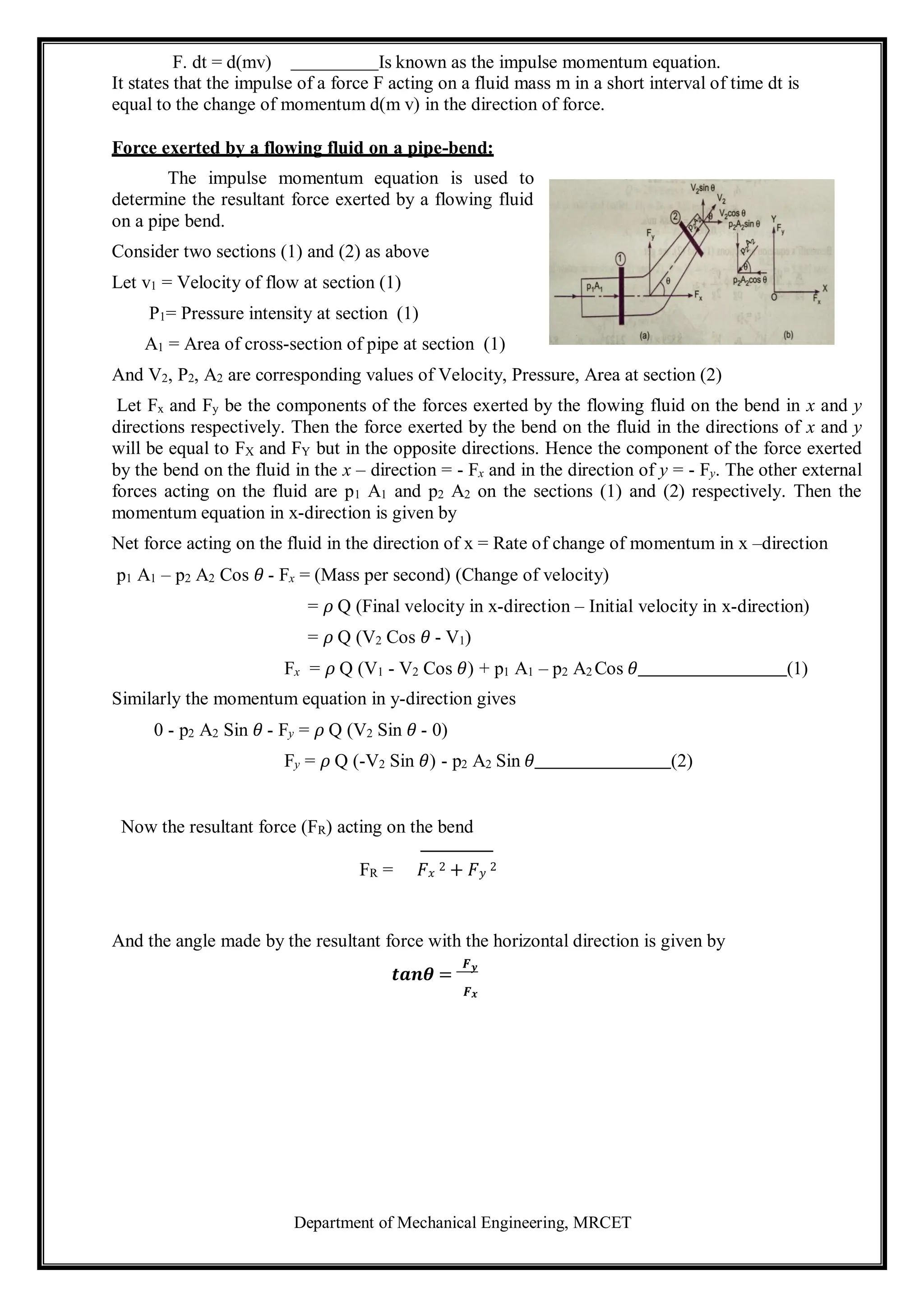
This force can be resolved in two components, one in the direction of the jet and the other
perpendicular to the direction of flow.
Then we have Fx = Component of Fn in the direction of flow.
𝐹𝑥= 𝐹𝑛cos 90 − 𝜃 = 𝐹𝑛sin 𝜃 − 𝜌𝑎𝑉2 sin 𝜃 × sin 𝜃
𝐹𝑥 = 𝜌𝑎𝑉2𝑠𝑖𝑛2𝜃 (1)
And F y = Component of Fn in the direction perpendicular to the flow.
𝐹𝑦= 𝐹𝑛sin 90 − 𝜃 = 𝐹𝑛cos 𝜃 = 𝜌𝑎𝑣2 sin 𝜃 × cos 𝜃
𝐹𝑦 = 𝜌𝑎𝑣2𝑠𝑖𝑛𝜃𝑐𝑜𝑠𝜃 (2)
c) Force exerted by a jet on a stationary Curved plate:
i) Jet strikes the curved plate at the centre:
The jet after striking the plate comes out
with same velocity, if the plate is smooth and
there is no loss of energy due to impact of the
jet, in the tangential direction of the curved
plate. The velocity at the out let of the plate
can be resolved in to two components, one in
the direction of the jet and other
perpendicular to the direction of jet.
Component of velocity in the direction of jet = −𝑉 𝐶𝑜𝑠𝜃
(-ve sign is taken as the velocity at out let is in the opposite direction of the jet of water coming
out from nozzle.)
Component of velocity perpendicular to the jet = V sin𝜃
Force exerted by the jet in the direction of the jet
Fx = Mass per sec (V1x – V2x)
Where V1x = Initial velocity in the direction of jet = V
V2x = Final velocity in the direction of jet = −𝑉 𝐶𝑜𝑠𝜃
Fx = 𝜌aV [V – (−𝑉 𝐶𝑜𝑠𝜃)] = 𝜌aV [V+ V Cos𝜃] = 𝜌aV2
(1 + Cos𝜃)-------------(1)
Similarly Fy = Mass per second (V1y – V2y)
Where V1y = Initial velocity in the direction of y = 0
V2y = Final velocity in the direction of y = V sin𝜃
Fy = 𝜌aV [0 – V Sin𝜃] = −𝜌aV2
Sin𝜃---------------(2)](https://image.slidesharecdn.com/fluidmechanics-241105055638-83e87bce/75/lecture-notes-on-fundamental-of-mechanical-engineering-72-2048.jpg)
![Department of Mechanical Engineering, MRCET
-ve sign means the force is acting in the downward direction.
In this case the angle of deflection of jet = 180° - 𝜃
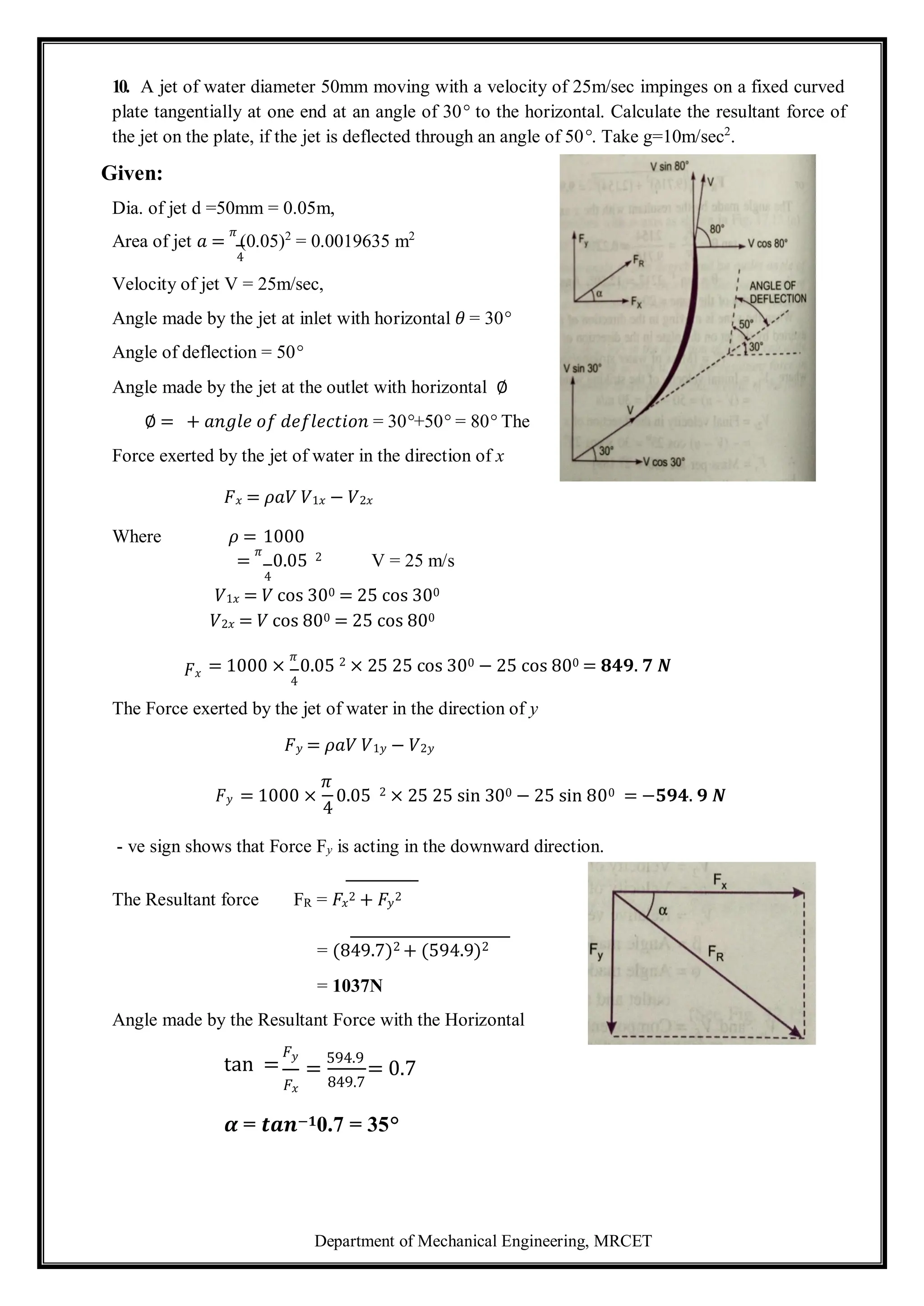
ii) Jet strikes the curved plate at one end tangentially when the plate is
symmetrical:
Let the jet strikes the curved fixed plate at one end tangentially. Let the curved plate is
symmetrical about x–axis. Then the angle made by the tangents at the two ends of the plate will
be same.
Let V = Velocity of jet of water.
𝜃 = Angle made by the jet with x–axis at the
inlet tip of the curved plate.
If the plate is smooth and loss of energy due to
impact is zero, then the velocity of water at the out
let tip of the curved plate will be equal to V. The
force exerted by the jet of water in the direction of x
and y are
Fx = (mass/sec) × (V1x – V2x)
= 𝜌aV [V Cos𝜃 − (−𝑉 𝐶𝑜𝑠𝜃)]
= 2 𝝆aV2
Cos𝜽
Fy = 𝜌aV (V1y – V2y) = 𝜌aV [V sin𝜃 −𝑉𝑆𝑖𝑛𝜃] = 0
iii) Jet strikes the curved plate at one end tangentially when the plate is un-
symmetrical:
When the curved plate is unsymmetrical about x- axis, then the angles made by tangents drawn at
inlet and outlet tips of the plate with x- axis will be different.
Let 𝜃 = Angle made by tangent at the inlet tip with x-axis.
∅ = Angle made by tangent at the outlet tip with x-axis
The two components of velocity at inlet are
V1x = V cos𝜃 and V1y = V sin𝜃
The two components of velocity at outlet are
V2x = −𝑉 cos ∅ and V2y = V sin ∅
The forces exerted by the jet of water in the directions of x and y are:
Fx = 𝜌aV (V1x – V2x) = 𝜌aV (V Cos𝜃 + V Cos ∅)
= 𝜌𝑎𝑉2 + 𝑐𝑜𝑠∅
Fy = 𝜌aV (V1y – V2y) = 𝜌aV [V sin𝜃 −V sin ∅] = 𝝆 a V2
(sin𝜽 - Sin ∅)](https://image.slidesharecdn.com/fluidmechanics-241105055638-83e87bce/75/lecture-notes-on-fundamental-of-mechanical-engineering-73-2048.jpg)
![Department of Mechanical Engineering, MRCET
FORCE EXERTED BY A JET ON MOVING PLATES
The fallowing cases of the moving plates will be considered:
a. Flat vertical plate moving in the direction of jet and away from the jet.
b. Inclined plate moving in the direction of jet and
c. Curved plate moving in the direction of jet or in the horizontal direction.
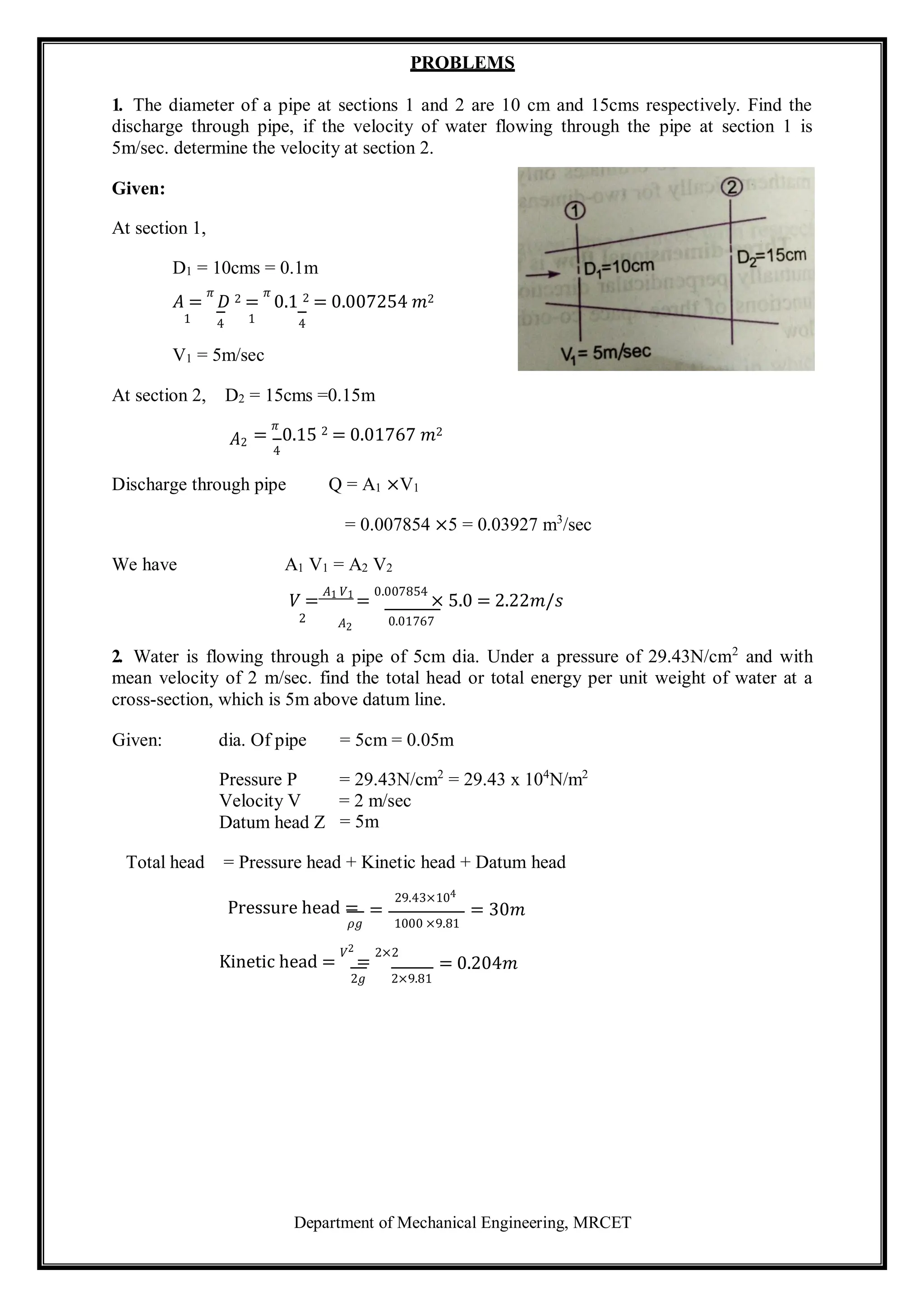
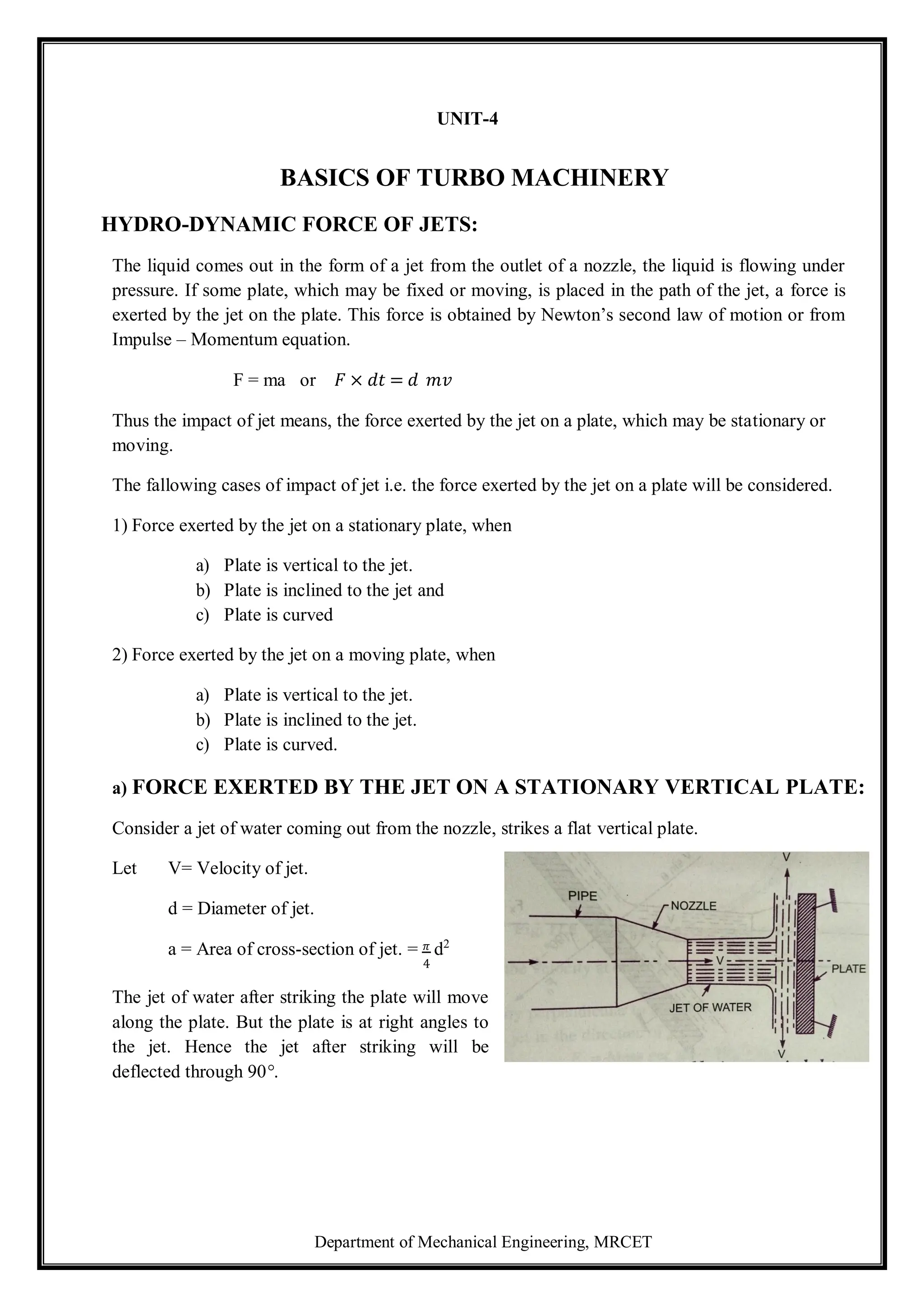
a) Force on flat vertical plate moving in the direction of jet:
Let a jet of water striking a flat vertical plate
moving with a uniform velocity away from the jet.
Let V = Velocity of jet.
a = Area of cross-section of jet.
u = Velocity of flat plate.
In this case, the jet does not strike the plate with a
velocity v, but it strikes with a relative velocity,
which is equal to the absolute velocity of jet of water
minus velocity of the plate.
Hence relative velocity of the jet with respect to plate = V – u
Mass of water striking the plate per second
= 𝜌 × 𝐴𝑟𝑒𝑎 𝑜𝑓 𝑗𝑒𝑡 × 𝑣𝑒𝑙𝑜𝑐𝑖𝑡𝑦 𝑤𝑖𝑡 𝑤𝑖𝑐 𝑗𝑒𝑡 𝑠𝑡𝑟𝑖𝑘𝑒𝑠 𝑡𝑒 𝑝𝑙𝑎𝑡𝑒
= 𝜌 a (V – u)
∴ Force exerted by the jet on the moving in the direction of the plate
Fx = mass of water striking per second × (Initial velocity with which water strikes – Final velocity)
= 𝜌 a (V – u)[( V – u) –0] = 𝜌 a (V – u)2---------- (1)
Since final velocity in the direction of jet is zero.
In this, case the work will be done by the jet on the plate, as the plate is moving. For stationary
plates, the work done is zero.
∴ The work done per second by the jet on the plate
= 𝐹𝑜𝑟𝑐𝑒 ×
Distance in the direction of force
Time
= Fx × u = 𝝆a(v – u)2
× u -------------(2)
In the above equation (2), if the value of 𝜌 for water is taken in S.I units (i.e.1000kg/m3
) the work
done will be in N m/s. The term
Nm
is equal to Watt (W).
s](https://image.slidesharecdn.com/fluidmechanics-241105055638-83e87bce/75/lecture-notes-on-fundamental-of-mechanical-engineering-74-2048.jpg)
![Department of Mechanical Engineering, MRCET
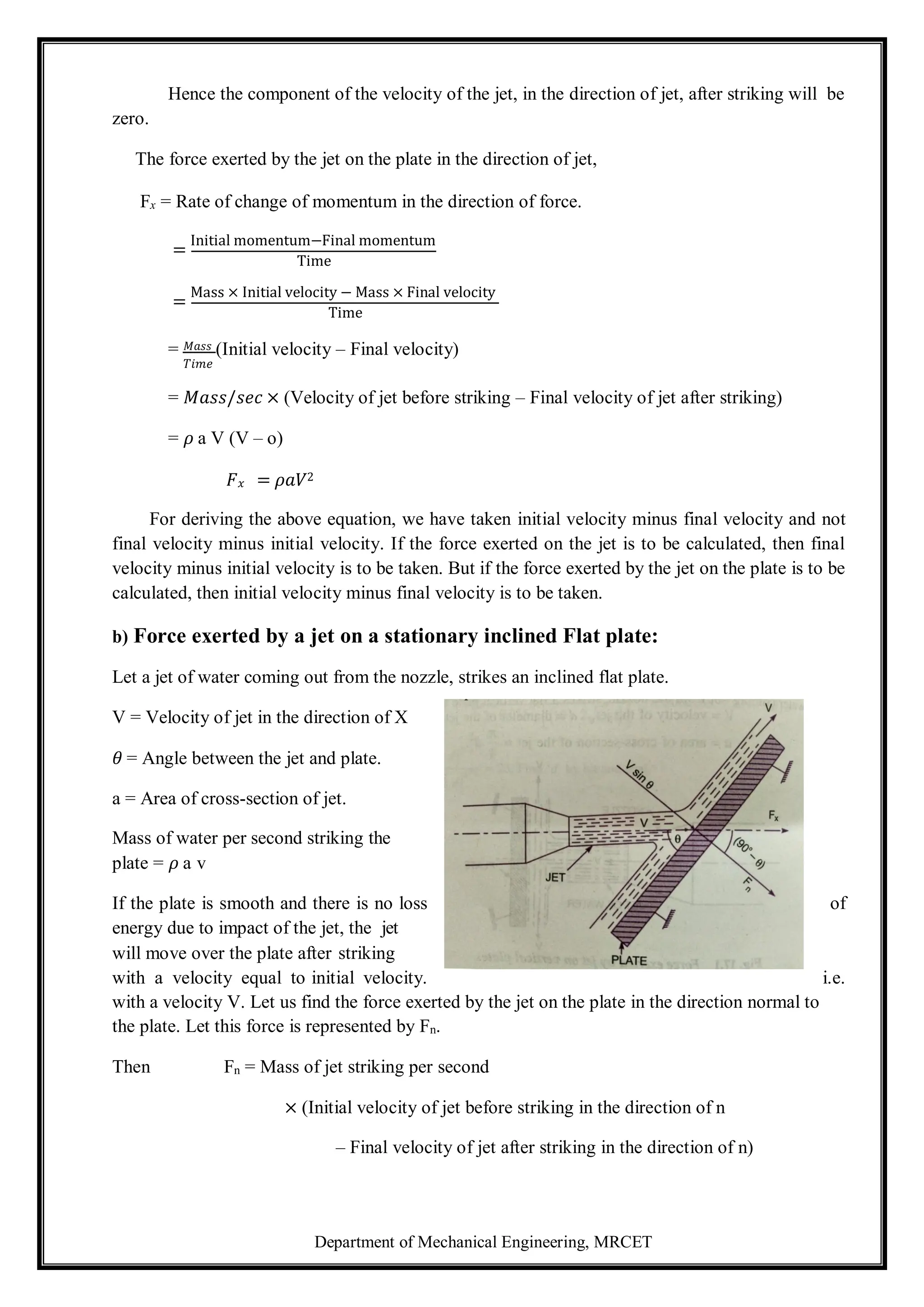
b) Force on inclined plate moving in the direction of jet:
Let a jet of water strikes an inclined plate, which is moving with a uniform velocity in the
direction of jet.
Let V = Absolute velocity of water.
u = Velocity of plate in the direction of jet.
a = Cross-sectional area of jet
𝜃 = Angle between jet and plate.
Relative velocity of jet of water = 𝑉 − 𝑢
The velocity with which jet strikes = 𝑉 − 𝑢
Mass of water striking per second = 𝜌 a (V – u)
If the plate is smooth and loss of energy due to impact of the jet is assumed zero, the jet of water
will leave the inclined plate with a velocity equal to 𝑉 − 𝑢 .
The force exerted by the jet of water on the plate in the direction normal to the plate is given as
Fn = Mass striking per sec x (Initial velocity in the normal direction with which jet strikes – final velocity)
= 𝜌 a (V – u) [(V – u) sin𝜃 − 0]
= 𝝆 a (V– u)2
sin𝜽
This normal force Fn is resolved in to two components, namely Fx and Fy in the direction of jet
and perpendicular to the direction of jet respectively.
𝐹𝑥 = 𝐹𝑛 𝑠𝑖𝑛𝜃 = 𝜌𝑎 𝑉 − 𝑢 2𝑠𝑖𝑛2𝜃
𝐹𝑦 = 𝐹𝑛 𝑐𝑜𝑠𝜃 = 𝜌𝑎 𝑉 − 𝑢 2𝑠𝑖𝑛𝜃𝑐𝑜𝑠𝜃
Work done per second by the jet on the plate
= Fx × Distance per second in the direction of x
= Fx × u = 𝜌a(V – u)2
sin2
𝜃 × u
= 𝝆 a (V – u)2
u sin2
𝜽 N m/sec](https://image.slidesharecdn.com/fluidmechanics-241105055638-83e87bce/75/lecture-notes-on-fundamental-of-mechanical-engineering-75-2048.jpg)
![Department of Mechanical Engineering, MRCET
c) Force on the curved plate when the plate is moving in the direction of jet:
Let a jet of water strikes a curved plate at the centre of the plate, which is moving with a
uniform velocity in the direction of jet.
Let V = absolute velocity of jet.
a = area of jet.
u = Velocity of plate in the direction of jet.
Relative velocity of jet of water or the velocity with
which jet strikes the curved plate = V – u
If the plate is smooth and the loss of energy due to
impact of jet is zero, then the velocity with which the
jet will be leaving the curved vane = (V – u)
This velocity can be resolved in to two components, one in the direction of jet and the other
perpendicular to the direction of jet.
Component of the velocity in the direction of jet = - (V – u) Cos𝜃
(-ve sign is taken as at the out let, the component is in the opposite direction of the jet).
Component of velocity in the direction perpendicular to the direction of jet = (V – u) sin𝜃
Mass of water striking the plate = 𝜌𝑎 × velocity with which jet strikes the plate.
= 𝜌𝑎 (V – u)
∴Force exerted by the jet of water on the curved plate in the direction of jet Fx
Fx = Mass striking per sec [Initial velocity with which jet strikes the plate in
the direction of jet −Final velocity]
= 𝜌𝑎 𝑉 − 𝑢 𝑉 − 𝑢 − − 𝑉 − 𝑢 cos 𝜃
= 𝜌 − 2 1 + cos 𝜃 (1)
Work done by the jet on the plate per second
= Fx ×Distance travelled per second in the direction of x
= 𝐹𝑥 × 𝑢 = 𝜌𝑎 𝑉 − 𝑢 2 1 + cos 𝜃 × 𝑢
= 𝜌𝑎 𝑉 − 𝑢 2 × 𝑢 1 + cos 𝜃](https://image.slidesharecdn.com/fluidmechanics-241105055638-83e87bce/75/lecture-notes-on-fundamental-of-mechanical-engineering-76-2048.jpg)
![Department of Mechanical Engineering, MRCET
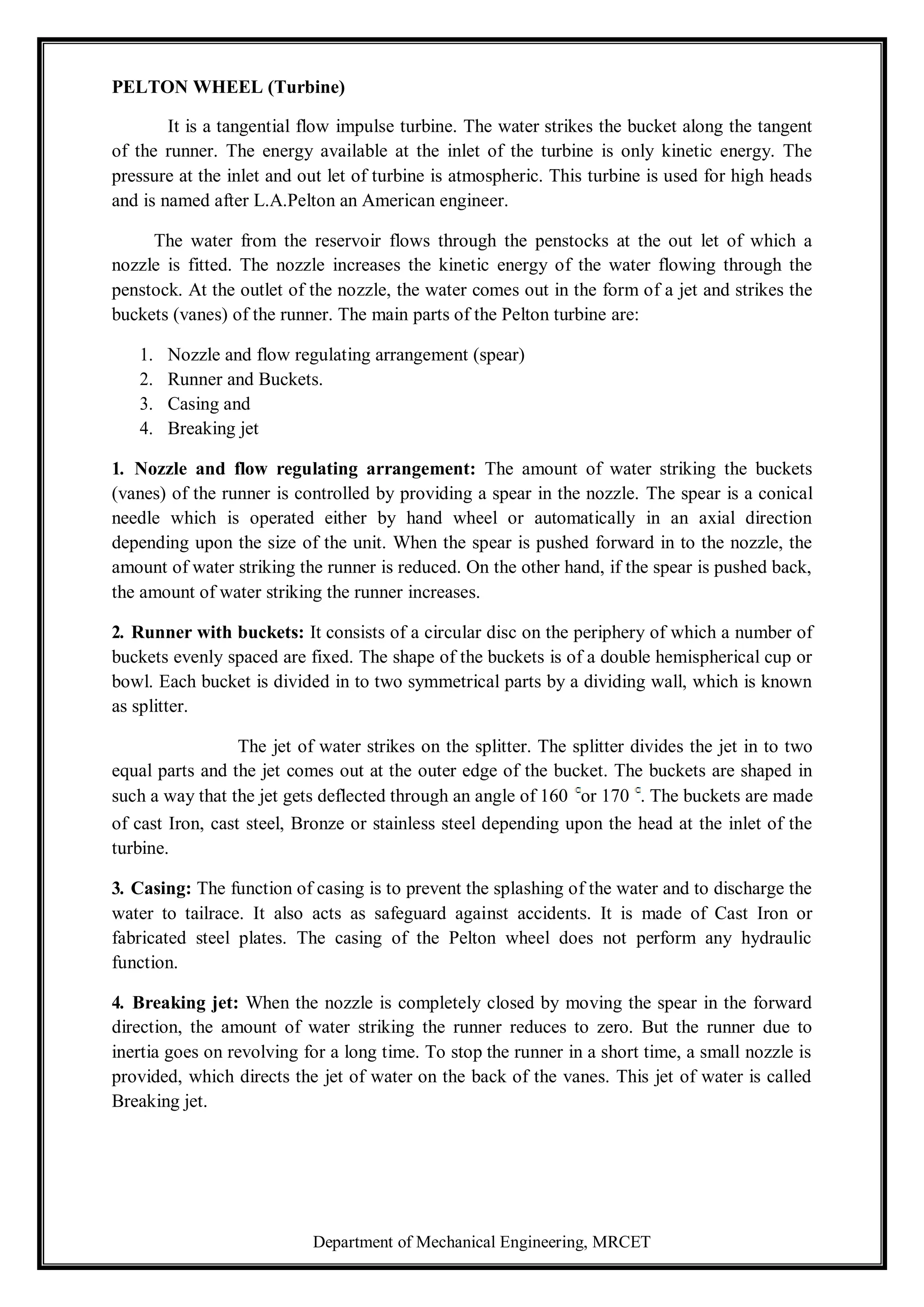
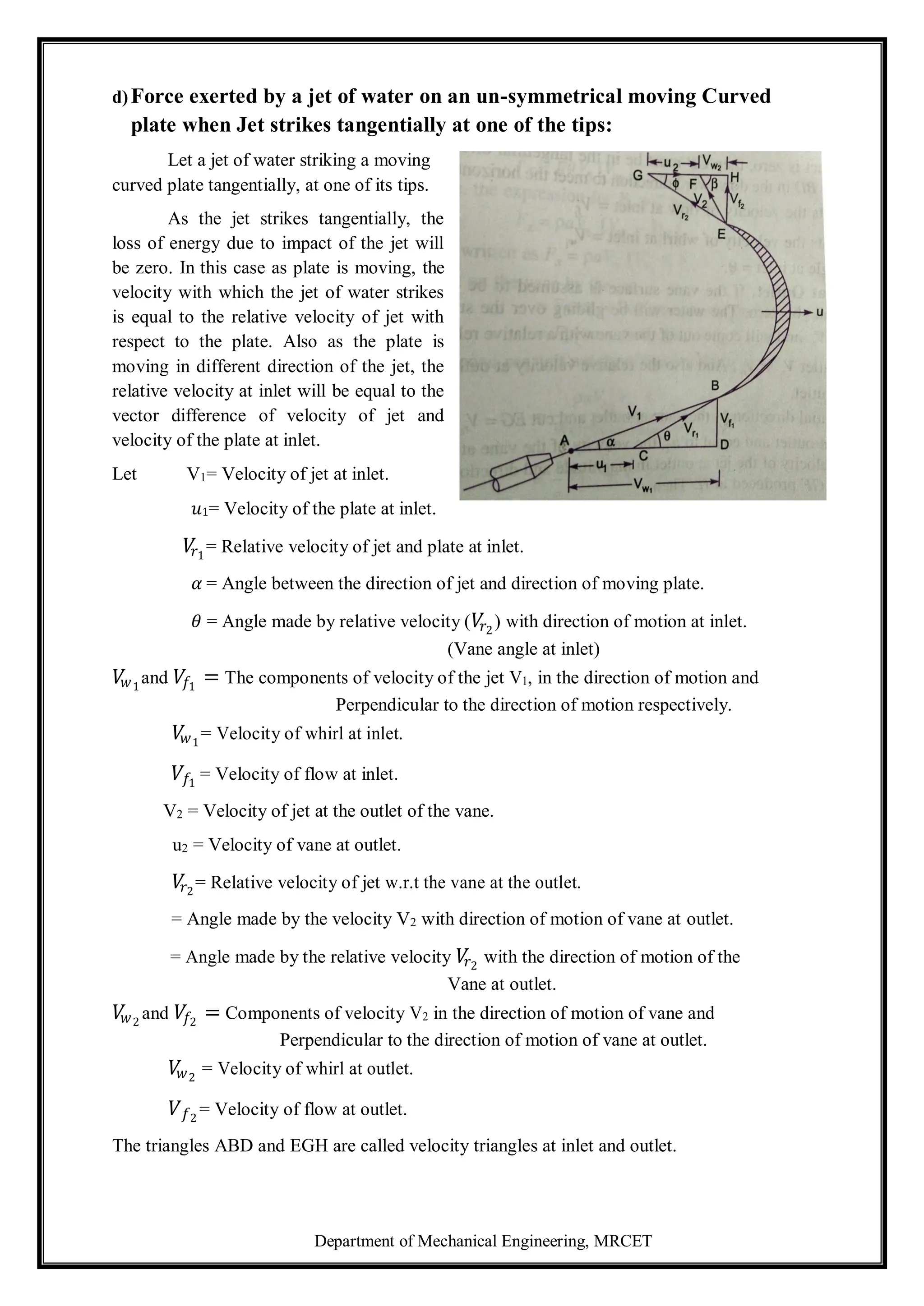
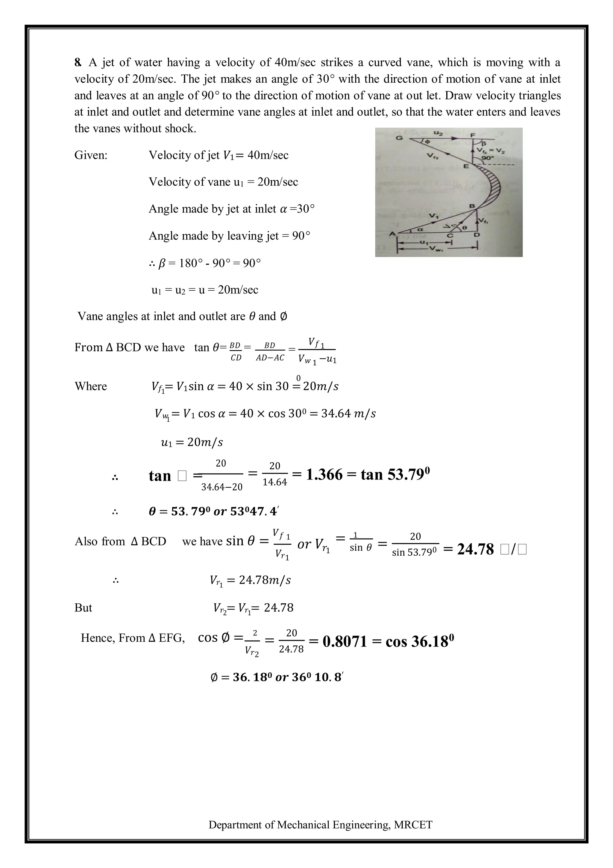
Velocity triangle at inlet: Take any point A and draw a line AB = V1 in magnitude and direction
which means line AB makes an angle 𝛼 with the horizontal line AD. Next draw a line AC = u1 in
magnitude. Join C to B. Then CB represents the relative velocity of the jet at inlet. If the loss of
energy at inlet due to impact is zero, then CB must be in the tangential direction to the vane at
inlet. From B draw a vertical line BD in the downward direction to meet the horizontal line AC
produced at D.
Then BD = Represents the velocity of flow at inlet = 𝑉𝑓1
AD = Represents the velocity of whirl at inlet = 𝑉
𝑤1
∠BCD = Vane angle at inlet = 𝜃
Velocity triangle at outlet: If the vane surface is assumed to be very smooth, the loss of energy
due to friction will be zero. The water will be gliding over the surface of the vane with a relative
velocity 𝑉
𝑟1
and will come out of the vane with a relative velocity𝑉
𝑟2
. This means that the relative
velocity at out let 𝑉
𝑟2
= 𝑉
𝑟1
. The relative velocity at outlet should be in tangential direction to the
vane at outlet.
Draw EG in the tangential direction of the vane at outlet and cut EG = 𝑉
𝑟2
. From G, draw a
line GF in the direction of vane at outlet and equal to u2, the velocity of vane at outlet. Join EF.
Then EF represents the absolute velocity of the jet at outlet in magnitude and direction. From E
draw a vertical line EH to meet the line GF produced at H.
Then, EH = Velocity of flow at outlet. = 𝑉𝑓2
.
FH = Velocity of whirl at outlet = 𝑉
𝑤2
∅ = Angle of vane at outlet
𝛽 = Angle made by V2 with the direction of motion of vane at outlet.
If vane is smooth and is having velocity in the direction of motion at inlet and outlet equal, then
we have
𝑢1 = 𝑢2 = 𝑢 = velocity of vane in the direction of motion and
𝑉
𝑟1
= 𝑉
𝑟2
Now mass of water striking the vane per second 𝜌𝑎𝑉
𝑟1 -------------------------
(1)
Where a= area of jet of water, 𝑉
𝑟1
= Relative velocity at inlet.
∴ Force exerted by the jet in the direction of motion
FX = Mass of water striking per second × [Initial velocity with which jet strikes in the
direction of motion – Final velocity of jet in the direction of motion]--------(2)](https://image.slidesharecdn.com/fluidmechanics-241105055638-83e87bce/75/lecture-notes-on-fundamental-of-mechanical-engineering-78-2048.jpg)
![Department of Mechanical Engineering, MRCET
9. A stationary vane having an inlet angle of zero degree and an outlet angle of 25°, receives
water at a velocity of 50m/sec. Determine the components of force acting on it in the direction of
jet velocity and normal to it. Also find the resultant force in magnitude and direction per unit
weight of the flow.
Given: Velocity of jet V = 50m/sec
Angle at outlet =25°
For the stationary vane, the force in the direction of jet.
𝐹𝑥 = 𝑀𝑎𝑠𝑠 𝑝𝑒𝑟 𝑠𝑒𝑐 × 𝑉1𝑥 − 𝑉2𝑥
Where 𝑉1𝑥 = 50m/sec , 𝑉2𝑥 = −50 cos 250 = −45.315
∴ Force in the direction of jet per unit weight of water 𝐹𝑥
𝐹 =
𝑀𝑎𝑠𝑠 / sec [50− −45.315 ]
=
𝑀𝑎𝑠𝑠 /sec
[50+45.315]
𝑥 𝑊𝑒𝑖𝑔 𝑡 𝑜𝑓 𝑤𝑎𝑡𝑒𝑟
/
𝑠
𝑒
𝑐
=
95.315
= 9.716 𝑁/𝑁
9.81
𝑚𝑎𝑠𝑠 /𝑠𝑒𝑐 ×𝑔
Force exerted by the jet in perpendicular direction to the jet per unit weight of flow
𝑉1 = 0 𝑉2𝑦 = 50 sin 250
𝐹𝑦 =
𝑀𝑎𝑠𝑠 / sec (𝑉1𝑦 − 𝑉 2 )
𝑔× 𝑚𝑎𝑠𝑠 𝑝𝑒𝑟 𝑠𝑒𝑐
=
(0−50 𝑆𝑖𝑛 25°)
=
−50 𝑆𝑖𝑛 25°
𝑔
= - 2.154 N
9.81
- ve sign means the force Fy is acting in the downward direction.
∴ Resultant Force per unit weight of water FR = 𝐹𝑥
2 + 𝐹𝑦
2
𝐹𝑅 = (9.716)2 + (2.154)2 = 9.952N
The angle made by the Resultant Force with x- axis
tan 𝜃 =
Fy
=
2.154
= 0.2217
Fx 9.716
𝜽 = 𝒕𝒂𝒏−𝟏0.2217 = 12.50°](https://image.slidesharecdn.com/fluidmechanics-241105055638-83e87bce/75/lecture-notes-on-fundamental-of-mechanical-engineering-87-2048.jpg)