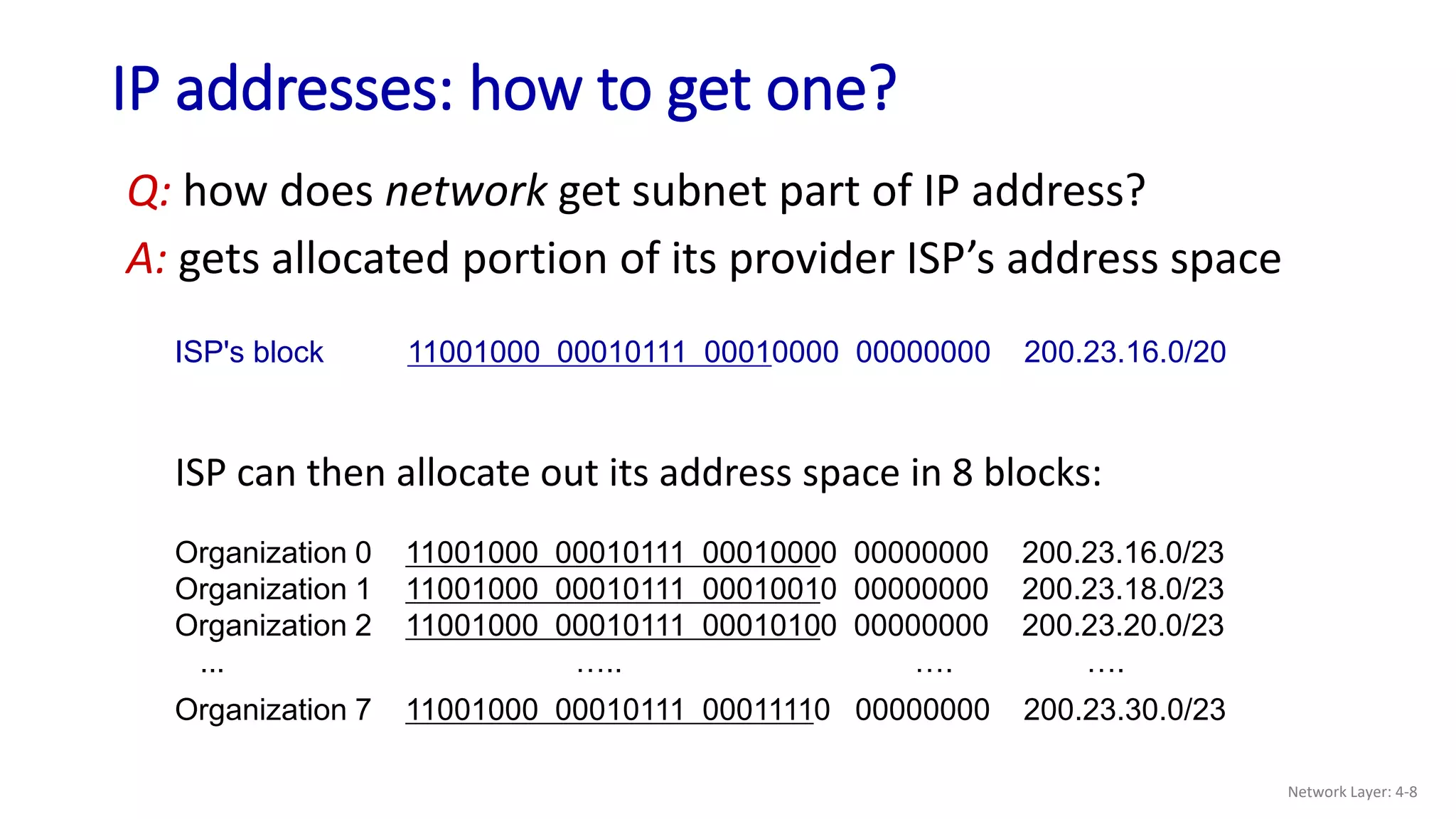
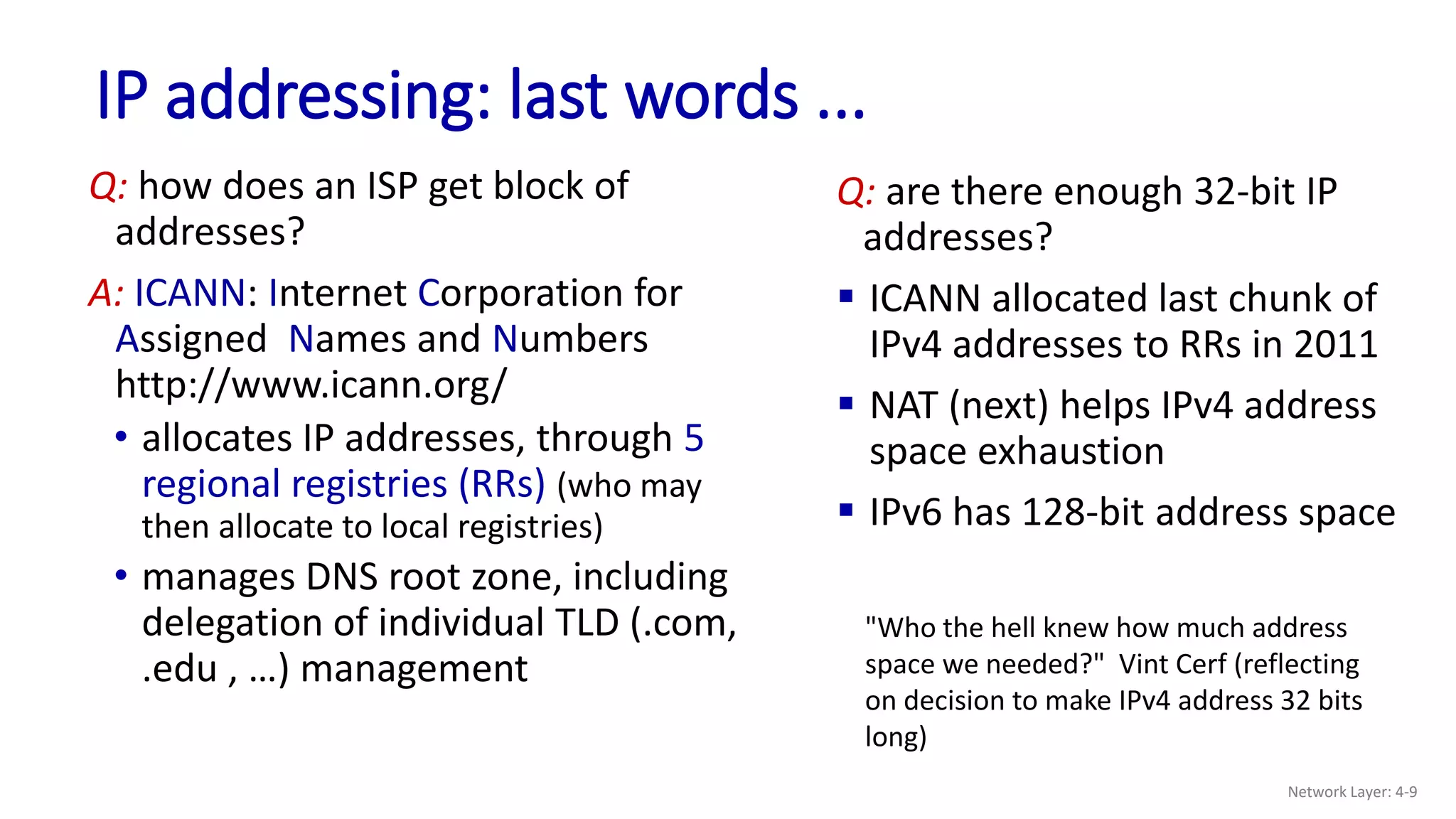
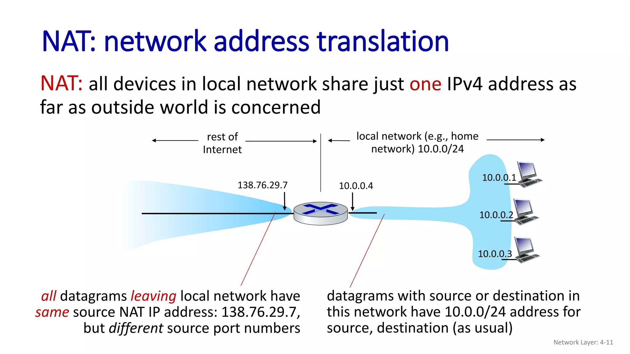
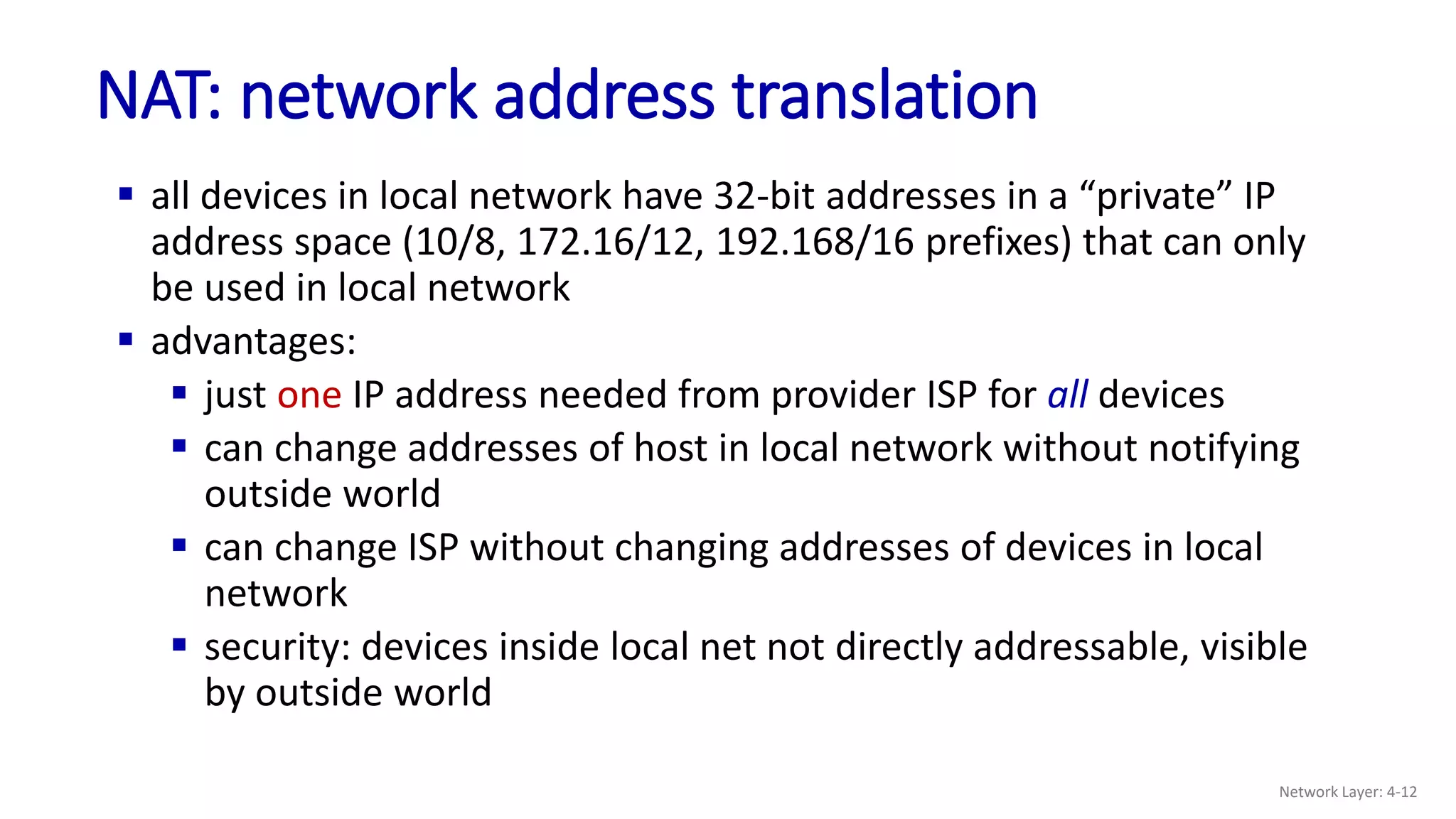
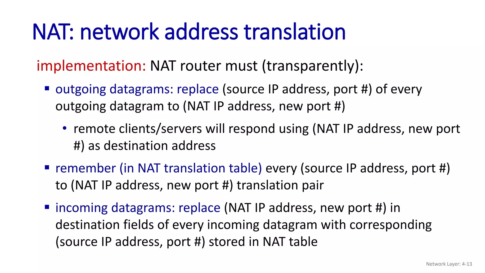
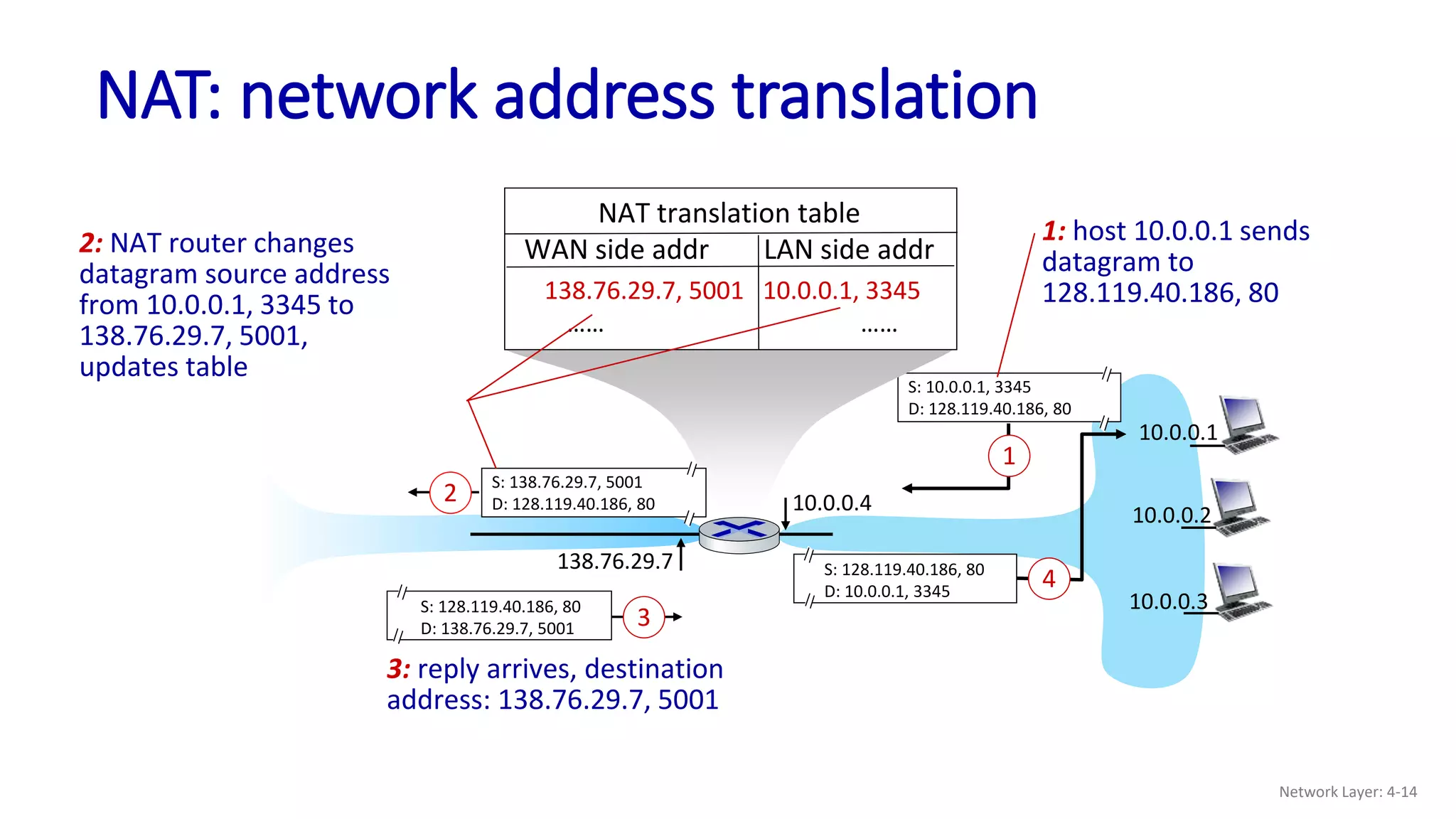
Host devices use either DHCP or static configuration to obtain an IP address from the network portion that is managed by the network administrator. Networks obtain IP address space from their upstream Internet Service Provider (ISP), which in turn receives IP address blocks from regional registries managed by ICANN. Network Address Translation (NAT) allows multiple devices to share a single public IP address, enabling networks with private addressing schemes to connect to the public Internet. NAT operates by rewriting source addresses and ports of outgoing packets and reversing translations for incoming packets matching entries in its mapping table.
![DHCP: Dynamic Host Configuration Protocol
goal: host dynamically obtains IP address from network server when it
“joins” network
can renew its lease on address in use
allows reuse of addresses (only hold address while
connected/on)
support for mobile users who join/leave network
DHCP overview:
host broadcasts DHCP discover msg [optional]
DHCP server responds with DHCP offer msg [optional]
host requests IP address: DHCP request msg
DHCP server sends address: DHCP ack msg
Network Layer: 4-2](https://image.slidesharecdn.com/lecture23dhcpandnat-221225134838-28ad2eac/75/Lecture-23-DHCP-and-NAT-pptx-2-2048.jpg)
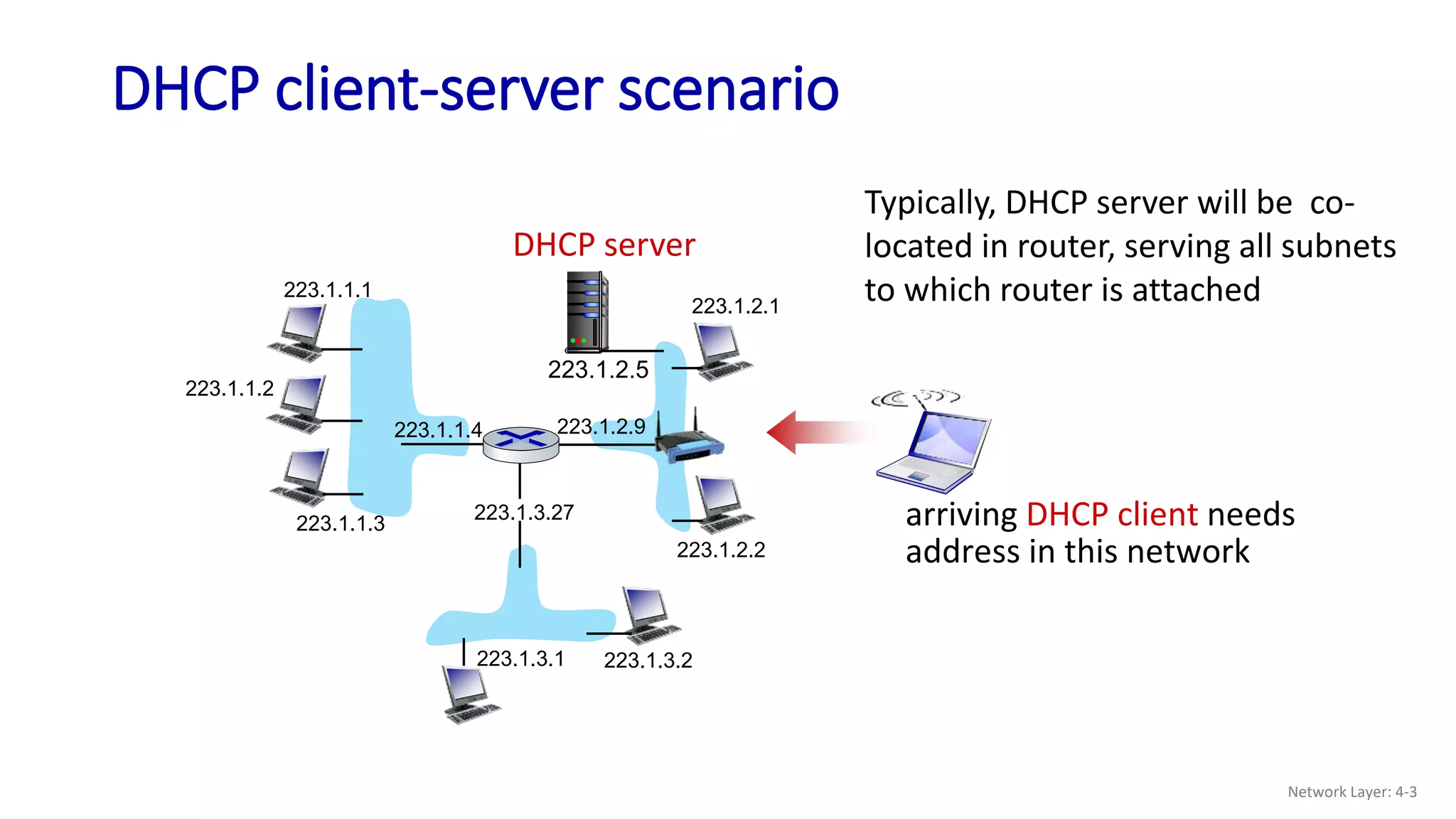
![DHCP client-server scenario
DHCP server: 223.1.2.5
Arriving client
DHCP discover
src : 0.0.0.0, 68
dest.: 255.255.255.255,67
yiaddr: 0.0.0.0
transaction ID: 654
DHCP offer
src: 223.1.2.5, 67
dest: 255.255.255.255, 68
yiaddrr: 223.1.2.4
transaction ID: 654
lifetime: 3600 secs
DHCP request
src: 0.0.0.0, 68
dest:: 255.255.255.255, 67
yiaddrr: 223.1.2.4
transaction ID: 655
lifetime: 3600 secs
DHCP ACK
src: 223.1.2.5, 67
dest: 255.255.255.255, 68
yiaddrr: 223.1.2.4
transaction ID: 655
lifetime: 3600 secs
Broadcast: is there a
DHCP server out there?
Broadcast: I’m a DHCP
server! Here’s an IP
address you can use
Broadcast: OK. I would
like to use this IP address!
Broadcast: OK. You’ve
got that IP address!
The two steps above can
be skipped “if a client
remembers and wishes to
reuse a previously
allocated network address”
[RFC 2131]
Network Layer: 4-4](https://image.slidesharecdn.com/lecture23dhcpandnat-221225134838-28ad2eac/75/Lecture-23-DHCP-and-NAT-pptx-4-2048.jpg)