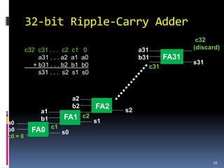
This document discusses binary arithmetic and how numbers are represented in binary. It covers:
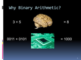
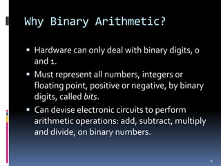
1. Why binary representation is used in digital circuits, as hardware can only deal with binary digits of 0 and 1.
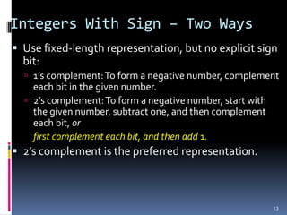
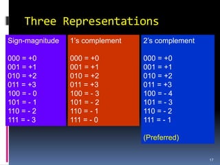
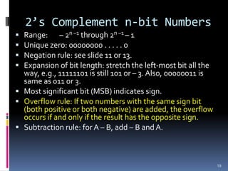
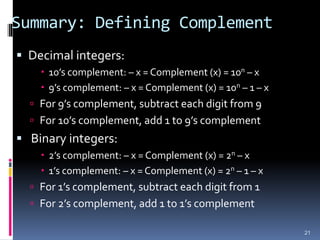
2. Different systems for representing signed integers in binary, including signed magnitude, 1's complement, and 2's complement representations. 2's complement is preferred as it has a unique zero value.
3. Arithmetic operations like addition, subtraction, and overflow handling in binary systems with a finite number of bits using the different signing methods.

![Summary
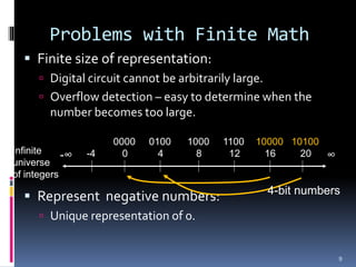
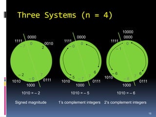
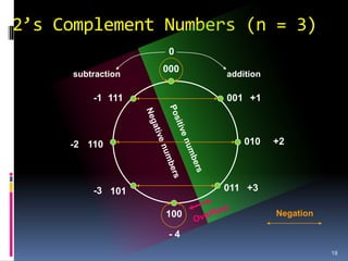
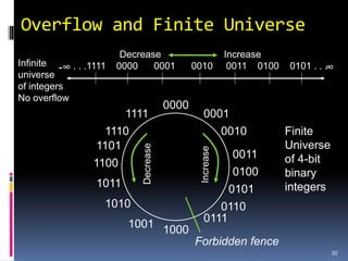
For a given number (n) of digits we have a finite
set of integers. For example, there are 103 = 1,000
decimal integers and 23 = 8 binary integers in 3-
digit representations.
We divide the finite set of integers [0, rn – 1],
where radix r = 10 or 2, into two equal parts
representing positive and negative numbers.
Positive and negative numbers of equal
magnitudes are complements of each other: x +
complement (x) = 0.
20](https://image.slidesharecdn.com/lec2binaryarithmetic-230804044247-73d5aae9/85/lec2_BinaryArithmetic-ppt-20-320.jpg)


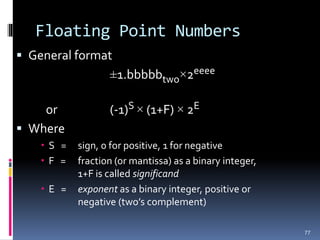

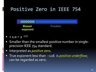
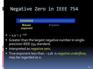
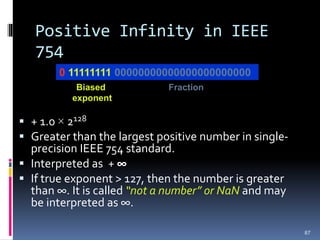
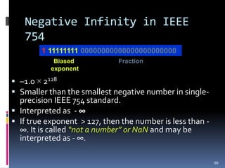
![IEEE 754 Floating Point
Standard
Biased exponent: true exponent range
[-126,127] is changed to [1, 254]:
Biased exponent is an 8-bit positive binary integer.
True exponent obtained by subtracting 127ten or
01111111two
First bit of significand is always 1:
± 1.bbbb . . . b × 2E
1 before the binary point is implicitly assumed.
Significand field represents 23 bit fraction after the binary
point.
Significand range is [1, 2), to be exact [1, 2 – 2-23]
81](https://image.slidesharecdn.com/lec2binaryarithmetic-230804044247-73d5aae9/85/lec2_BinaryArithmetic-ppt-81-320.jpg)