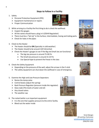
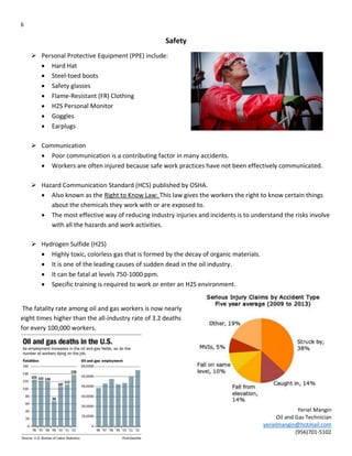
SlideShare a Scribd company logo
1
Yeriel Mangin
Oil and Gas Technician
yerielmangin@hotmail.com
(956)701-5102
Lease Operator
11 Steps to follow
2
Yeriel Mangin
Oil and Gas Technician
yerielmangin@hotmail.com
(956)701-5102
Content
Objective………………………………………………………………………………………………………………. 3
Introduction………………………………………………………………………………………………………….. 3
Step to follow in a facility …………………………………………………………………………………… 4, 5
Safety……………………………………………………………………………………………………………………. 6
Equipment and function “The Wellhead”………………….……………………………………………. 7
Equipment and function “Heater”…………………………………………………………………………. 8
Safety Equipment…………………………………………………………………………………………………...9
High and Low Pressure Separator…………………………………………………………………………… 10
Chemical Tank………………………………………………………………………………………………………….11
Clean Facility…………………………………………………………………………………………………………….11
Stock Tanks…………………………………………………………………………………………………………….. 12
The Rock…………………………………………………………………………………………………………………. 12
Data………………………………………………………………………………………………………………………… 12
Troubleshooting…………………………………………………………………………………………………….…13
Reference.………………………………………………………………………………………………………………. 14
3
Yeriel Mangin
Oil and Gas Technician
yerielmangin@hotmail.com
(956)701-5102
Objective
 The subject of this presentation is to show and tell what is like to be out in the field.
 The overall goal of the presentation is to involve or bring the attention of the youth into
the oil industry.
Introduction
 First of all, thank you Lewis Energy for giving me this opportunity to do my internship
with you. This presentation describes some of the things I did and learned out in the
field using the knowledge I learned in the Oil and Gas program.
4
Yeriel Mangin
Oil and Gas Technician
yerielmangin@hotmail.com
(956)701-5102
Steps to Follow in a Facility
1. Safety
 Personal Protective Equipment (PPE)
 Equipment maintenance or repairs
 Proper Communication
2. While arriving to a Facility the first thing to do is check the wellhead.
 Inspect the gauges
 All the valves should have a plug in it (OSHA Regulation)
 There must be a “Set Up” in the Surface, Intermediate, Casing and tubing parts.
 Check for leaks in the pipes
3. Check to the Heater
 The heater should be ON (Specially in cold weather)
 The Heater should to be around 120 Fahrenheit
 Check the Heater’s gauges to see if the Big and Small Joe are functional.
 The big Joe pressure is around 75-90 Psi
 The Small Joe pressure is around 15-22 Psi
 Use Special tape to prevent the freeze in the Joes
4. Check the Safety Equipment
 Depending on the pressure of the well, adjust the arrows in the E-stick
 The safety equipment can shut down the wellhead in case of emergency.
5. Examine the High and Low Pressure Separators
 Revise the dump valve
 Control boxes (adjust the spring)
 Back Pressure Regulator (pressure inside the regulator)
 Glass tube (The levels of water and oil)
 Any closed valves
 The weather cap
6. The rocket bottle is an important equipment
 It is the one that supplies pressure to the entire facility
 Bleed out the water inside
5
Yeriel Mangin
Oil and Gas Technician
yerielmangin@hotmail.com
(956)701-5102
7. Chemical tanks
 Check the pumping time of the chemical added
 Adjust the timer on the chemical pump
8. Clean the facility
 KEEP IT CLEAN
9. Stock tanks
 Use the Color Cut (If the tank is oil and water)
 Wait 5-8 sec then pull out the steel tape so the chemical can
change color
 If it is just water or oil, just measure with the steel tape
 The tank’s levels should stay low at all times
 Clean the measuring tape afterwards
10. Reading of the Rock
 Take readings such as:
 Wellhead Pressure
 Static Pressure
 Differential pressure
 Temperature
 Spot (Predict the amount of MCF the
Wellhead is going to make that day)
11. Data
 All the collected data should be uploaded into a special program
6
Yeriel Mangin
Oil and Gas Technician
yerielmangin@hotmail.com
(956)701-5102
Safety
 Personal Protective Equipment (PPE) include:
 Hard Hat
 Steel-toed boots
 Safety glasses
 Flame-Resistant (FR) Clothing
 H2S Personal Monitor
 Goggles
 Earplugs
 Communication
 Poor communication is a contributing factor in many accidents.
 Workers are often injured because safe work practices have not been effectively communicated.
 Hazard Communication Standard (HCS) published by OSHA.
 Also known as the Right to Know Law: This law gives the workers the right to know certain things
about the chemicals they work with or are exposed to.
 The most effective way of reducing industry injuries and incidents is to understand the risks involve
with all the hazards and work activities.
 Hydrogen Sulfide (H2S)
 Highly toxic, colorless gas that is formed by the decay of organic materials.
 It is one of the leading causes of sudden dead in the oil industry.
 It can be fatal at levels 750-1000 ppm.
 Specific training is required to work or enter an H2S environment.
The fatality rate among oil and gas workers is now nearly
eight times higher than the all-industry rate of 3.2 deaths
for every 100,000 workers.
7
Yeriel Mangin
Oil and Gas Technician
yerielmangin@hotmail.com
(956)701-5102
Equipment and function “The Wellhead”
 Wing Valve- is the first mechanism used to close manually the well.
 Actuator- A safety system to shut-down the well automatically.
 Choke- An equipment used to decrease the pressure coming from the
Well. (The pressure passing through the choke should be
The same, ALWAYS)
 The Isolation Valve- The last part of the well before the pressure
(Oil/gas) goes to the facility
 Soap launcher- An old method of “Helping” the well to increase the
Pressure or dissolve water inside the well
 Plunger- The modern method of “Helping” the well to increase the
Pressure. (Release a rod into the well to accumulate pressure
Thus when it has enough pressure it can lift the rod and
Pressure up the well.
 All the parts of the Christmas tree should have a "set up"
For example the surface set up, intermediate set up,
Casing set up, tubing set
up.
 A proper “Set UP” has
Seven parts:
Bushing, Nipple, 'T" pipe,
(2) Needle Valve, plugs
and Gauge.
Incomplete casing Set Up Complete casing Set Up
8
Yeriel Mangin
Oil and Gas Technician
yerielmangin@hotmail.com
(956)701-5102
Equipment and Function “Heater”
 Heater- it heats the fluids that comes from the well.
The reason why some wells need a heater and others don’t
depends in some factors for example: the fluids are already
Warm/hot or the difference in pressure does not exceed
300 psi.
Some parts of the heater are:
 Big Joe- The pressure should always be between 75-90 psi
lower the pressure that comes from the well.
 Small Joe-The pressure should always be around 15-22 psi
 Lower the pressure even more from the well to the Big Joe to the Small Joe (From here
there are two gas pipes 1) for the Pilot 2) to keep the heater’s flame ON).
 Gauges- to read the temp of the Heater
 Heater’s Regulator- To maintain a certain temperature (If the temp exceeds the
adjusted temp, it will shut down the gas line).
 One way to prevent equipment from freezing is to wrap up the equipment with
special tape.
Without insulate tape in cold weather With insulate tape in cold weather
9
Yeriel Mangin
Oil and Gas Technician
yerielmangin@hotmail.com
(956)701-5102
Safety Equipment
 The safety equipment in the facility can shut down the well head automatically:
1. E-stick" boxes (2)
Adjusted a max and min pressure in the box, thus if the pressure reaches the needles, it
automatically shuts down the
wellhead.
 There are two boxes:
2. Actuator:
 When the "wheel" is outside
(First picture) and it has
pressure the actuator will let
pass the pressure to the next
phase (Heater/High-low
Separator).
 When the "wheel" is outside
(First picture) and it does not
have pressure the actuator will shut down the wellhead.
 When the "wheel" is inside (Second picture) the actuator is in by-pass, thus you can make any
arrangements you need to make.
 "The purpose of the wheel is to adjust a plate inside the actuator so you can put it on by-pass or shut
down the wellhead."
3. Versa Valve
 Controls the pressure that helps the actuator to stay open; you can manually or remotely close it from
the Office.
4. Pineapple
 A third (floater/check) in the low pressure separator. The pineapple does not let the
(water/condensate) to get to a certain level inside the separator (It is like your back up) if the
water reaches the pineapple level it immediately shuts down the well thus the
(water/condensate) do not reaches the flare tower.
Normally right next to the
Heater or Header
Right next to the High Pressure
separator
First Picture Second Picture
10
Yeriel Mangin
Oil and Gas Technician
yerielmangin@hotmail.com
(956)701-5102
Figure 1
High and low Pressure Separator
 Control Valve (Dumper) – is a valve used to control conditions such as flow, pressure, temperature, and
liquid level by fully or partially opening or closing the valve. Figure 1
 Control box- Controls the level of fluids inside the separators.
Figure 2
 Glass tube- is outside the low pressure separator and shows you
the levels of water/oil inside the separator. Looking at the
glass-tube the person can adjust the spring (inside the control
box) to level up the water and oil.
 Back pressure regulator- Figure 3 and Figure 4
 This equipment has two functions:
1) To bleed out the extra pressure in the separator; if there is
any excess pressure from the high to low separator, the
regulator sends the extra pressure to flare it.
2) To keep a certain amount of pressure inside the low separator
thus the pressure can take the water/condensate to the tanks.
 Weather cap- There should always be a “cap” at the top of all the separators. The purpose of the
weather “cap” is when there is an extra pressure (that exceeds the limits of the separator’s capacity)
release the pressure and the cap pops out of the separator. What this mean sometimes is that maybe
the levels of pressure need to be adjusted.
 Pineapple- A third (floater/check) in the low pressure separator. The pineapple does not
let the (water/condensate) get to a certain level inside the separator (it is like your back
up) if the water reaches the pineapple level it immediately shuts down the well thus the
(water/condensate) do not reaches the flare tower. Figure 5
 Check Valve- Is a type of valve that allows fluids to flow in one direction but closes
automatically to prevent flow in the opposite direction (backflow). Figure 6
In the image on the right, you can
see some of the equipment
describe above.
Figure 2
Figure 3 Figure 4
Figure 5
Figure 6
11
Yeriel Mangin
Oil and Gas Technician
yerielmangin@hotmail.com
(956)701-5102
Chemical Tank
 Some facilities and wellheads have more than one tank, the reason for
having several tanks is because the facility needs different chemical
substances for example:
 Scavenger: to control the H2S in the wellhead, facility, tanks, etc.
 Corrosion Inhibitor: To prevent the corrosion in the wellhead and
other parts in the facility.
 Outside the tank there is a small pump with timer, this pump constantly
sends a certain amount of chemical to the well, but it all depends in the
amount of H2S the well contains. (The more H2S the more scavenger are
needed)
 The lease operator needs to measure the time length of all the chemical tanks thus when the tanks are
almost empty, he must have a new tank ready.
Clean facility
Keeping clean all the wellheads, heaters, separators, tanks, etc. is a vital thing do.
 There should not be any grass/weed near the equipment. (Use a shovel to cut off or weed killer spray)
 There should not be any tools left out. (Wrench, screws, metal pipes, etc.)
 KEEP IT CLEAN!!!
12
Yeriel Mangin
Oil and Gas Technician
yerielmangin@hotmail.com
(956)701-5102
Stock tanks
 Onshore tanks usually store 3-7 days of oil/water production.
 Before gauging a tank pay careful attention to the H2S apparatus. (It may save your life)
 An “Old Method” of measuring the amount of oil in a tank is shown below:
 A gauger lowers a steel tape that has been carefully grounded with a weight on the end, into the
tank until it touches the bottom.
 The highest point at which oil wets the tape shows the level or height of oil/water in the tank.
Note: Some small facilities have only one storage tank, for oil and water of a well.
Some types of sampling methods are:
 Thief sampling or something called Core Sampling. The sampler lowers a thief to
obtain an oil/water sample from a storage tanks. Figure 7
 Bottle Sampling- A better but more difficult method of manual
sampling. Because of the difficult nature of this method, it is rarely
used for lease tanks. Figure 8
 A “Modern Method” is using radar to get the measures inside the tanks.
 The tank’s levels of oil/water should always stay low.
The Rock
 The rock is an electronic equipment that shows you different readings such as:
a) Wellhead pressure
b) Static Pressure
c) Differential Pressure
d) Temperature
e) Spot (Predict amount of MCF the wellhead is going to make that day)
Data
 At the end of the day the lease operator needs to upload the daily data from the
wells into a program.
 Most of the companies have specializes program to upload the daily
readings of the wells.
Figure 7
Figure 8
13
Yeriel Mangin
Oil and Gas Technician
yerielmangin@hotmail.com
(956)701-5102
Troubleshooting
 The spot reading is ZERO. What can cause the problem? (Always start from the wellhead)
 One of the wheels is closed.
 There is an Ice Block in the Choke of the wellhead
 The "Safety Equipment" shuts down the actuator from the wellhead. (Low pressure or high pressure
inside the pipelines)
 There is an Ice Block in the Choke of the Heater.
 Gas Control Shuts down the actuator.
 The pineapple (Separator) is full with liquids
 A tank with condensate has water inside. Why?
 Too much water passing from the wellhead to the separators.
 The "springs" (Control Box) are stuck (Bad function).
 The Control Valve (Dumper) are calibrated incorrectly (depends on the well).
 The "Check" Valve is broken.
 Why shut down a wellhead?
 To increase the pressure in the well, because the pressure is too low.
 Make a repair in some parts of the Christmas tree.
 To make sure the readings from the Rock and Gauge are the same.
 Reasons why the Heater can be OFF?
 No gas passing to the Heater.
 The weather (too cold).
 The fluids from the wellhead are warm/hot.
 Obstruction inside the choke
 The Big Joe and Small Joe are frozen.
 The Temp exceeds the adjusted temp.
 The adjusted temp and the actual temp are not calibrated correctly.
 The gas valve is closed.
 The pilot is off.
 The low pressure separator is full with liquids. Why?
 The pipes are closed. (Someone forgot to open them).
 The control boxes are not adjusted correctly.
 The floaters are broken.
 The pineapple is not working.
 The "Back pressure Regulator" is not working properly. (Not enough pressure to send the water to the
tanks)
 The Control Valve (Dumper) is not working correctly.
 The "Check" valve is broken.
 The Glass tube is dirty; thus the person cannot have an actual reading between water and condensate.
14
Yeriel Mangin
Oil and Gas Technician
yerielmangin@hotmail.com
(956)701-5102
Reference
 http://www.npr.org/2013/12/27/250807226/on-the-job-deaths-spiking-as-oil-drilling-quickly-expands
 http://www.post-gazette.com/business/2013/12/01/Oil-and-gas-fatalities-spike-with-
boom/stories/201312010086

More Related Content

What's hot

ELECTRONIC THERMOMETER USING MICROCONTROLLER
ELECTRONIC THERMOMETER USING MICROCONTROLLERELECTRONIC THERMOMETER USING MICROCONTROLLER
ELECTRONIC THERMOMETER USING MICROCONTROLLER
Rajesh Pandiyan
 
Boiler Loss of Flame Protection- MFT
Boiler Loss of Flame Protection- MFTBoiler Loss of Flame Protection- MFT
Boiler Loss of Flame Protection- MFT
Tahoor Alam Khan
 
ETS Trip.pptx
ETS Trip.pptxETS Trip.pptx
ETS Trip.pptx
ssuser28a1a31
 
Panic alarm circuit final PPT.pptx
Panic alarm circuit final PPT.pptxPanic alarm circuit final PPT.pptx
Panic alarm circuit final PPT.pptx
TusharSingh990575
 
training reportON Thermal power plantt (nashik tps)pdf
 training reportON Thermal power plantt (nashik tps)pdf training reportON Thermal power plantt (nashik tps)pdf
training reportON Thermal power plantt (nashik tps)pdf
Sagar Mehta
 
How to Improve Steam Turbine Head Rate and Increase Output
How to Improve Steam Turbine Head Rate and Increase OutputHow to Improve Steam Turbine Head Rate and Increase Output
How to Improve Steam Turbine Head Rate and Increase Output
Margaret Harrison
 
Thermal Power Plant Simulator Operations Training
Thermal Power Plant Simulator Operations TrainingThermal Power Plant Simulator Operations Training
Thermal Power Plant Simulator Operations Training
Manohar Tatwawadi
 
Gas Flare Stack Process
Gas Flare Stack ProcessGas Flare Stack Process
Gas Flare Stack Process
Shad Ibrahim
 
Scoop coupling
Scoop couplingScoop coupling
Scoop coupling
JISHNU V
 
Steam turbine types
Steam turbine typesSteam turbine types
Steam turbine types
Md. Irfan Uddin Sayeem
 
DIESEL GENERATOR DETAILS
DIESEL GENERATOR DETAILSDIESEL GENERATOR DETAILS
DIESEL GENERATOR DETAILS
NTPC
 
Design and Development of Child Rescue Mechanism from Open Bore Well
Design and Development of Child Rescue Mechanism from Open Bore WellDesign and Development of Child Rescue Mechanism from Open Bore Well
Design and Development of Child Rescue Mechanism from Open Bore Well
IRJET Journal
 
Boiler safety
Boiler safetyBoiler safety
Boiler safety
Santosh Kumar
 
condensate system
condensate systemcondensate system
condensate system
vikrantdesh
 
DC failiure at NTPC Tanda
DC failiure at NTPC TandaDC failiure at NTPC Tanda
DC failiure at NTPC Tanda
RAVI PAL SINGH
 
THERMAL POWER PLANT OPERATIONS
THERMAL POWER PLANT OPERATIONSTHERMAL POWER PLANT OPERATIONS
THERMAL POWER PLANT OPERATIONS
Manohar Tatwawadi
 
2 c industrial hydraulic circuits
2 c industrial hydraulic circuits2 c industrial hydraulic circuits
2 c industrial hydraulic circuits
Dr.R. SELVAM
 
Pressure Safety Valve Sizing - API 520/521/526
Pressure Safety Valve Sizing - API 520/521/526Pressure Safety Valve Sizing - API 520/521/526
Pressure Safety Valve Sizing - API 520/521/526
Vijay Sarathy
 
Steam Turbine and Condenser
Steam Turbine and CondenserSteam Turbine and Condenser
Steam Turbine and Condenser
Mulugeta Wotango
 
Performance calculation for feed water heater
Performance calculation  for feed water heaterPerformance calculation  for feed water heater
Performance calculation for feed water heater
SHIVAJI CHOUDHURY
 

What's hot (20)

ELECTRONIC THERMOMETER USING MICROCONTROLLER
ELECTRONIC THERMOMETER USING MICROCONTROLLERELECTRONIC THERMOMETER USING MICROCONTROLLER
ELECTRONIC THERMOMETER USING MICROCONTROLLER
 
Boiler Loss of Flame Protection- MFT
Boiler Loss of Flame Protection- MFTBoiler Loss of Flame Protection- MFT
Boiler Loss of Flame Protection- MFT
 
ETS Trip.pptx
ETS Trip.pptxETS Trip.pptx
ETS Trip.pptx
 
Panic alarm circuit final PPT.pptx
Panic alarm circuit final PPT.pptxPanic alarm circuit final PPT.pptx
Panic alarm circuit final PPT.pptx
 
training reportON Thermal power plantt (nashik tps)pdf
 training reportON Thermal power plantt (nashik tps)pdf training reportON Thermal power plantt (nashik tps)pdf
training reportON Thermal power plantt (nashik tps)pdf
 
How to Improve Steam Turbine Head Rate and Increase Output
How to Improve Steam Turbine Head Rate and Increase OutputHow to Improve Steam Turbine Head Rate and Increase Output
How to Improve Steam Turbine Head Rate and Increase Output
 
Thermal Power Plant Simulator Operations Training
Thermal Power Plant Simulator Operations TrainingThermal Power Plant Simulator Operations Training
Thermal Power Plant Simulator Operations Training
 
Gas Flare Stack Process
Gas Flare Stack ProcessGas Flare Stack Process
Gas Flare Stack Process
 
Scoop coupling
Scoop couplingScoop coupling
Scoop coupling
 
Steam turbine types
Steam turbine typesSteam turbine types
Steam turbine types
 
DIESEL GENERATOR DETAILS
DIESEL GENERATOR DETAILSDIESEL GENERATOR DETAILS
DIESEL GENERATOR DETAILS
 
Design and Development of Child Rescue Mechanism from Open Bore Well
Design and Development of Child Rescue Mechanism from Open Bore WellDesign and Development of Child Rescue Mechanism from Open Bore Well
Design and Development of Child Rescue Mechanism from Open Bore Well
 
Boiler safety
Boiler safetyBoiler safety
Boiler safety
 
condensate system
condensate systemcondensate system
condensate system
 
DC failiure at NTPC Tanda
DC failiure at NTPC TandaDC failiure at NTPC Tanda
DC failiure at NTPC Tanda
 
THERMAL POWER PLANT OPERATIONS
THERMAL POWER PLANT OPERATIONSTHERMAL POWER PLANT OPERATIONS
THERMAL POWER PLANT OPERATIONS
 
2 c industrial hydraulic circuits
2 c industrial hydraulic circuits2 c industrial hydraulic circuits
2 c industrial hydraulic circuits
 
Pressure Safety Valve Sizing - API 520/521/526
Pressure Safety Valve Sizing - API 520/521/526Pressure Safety Valve Sizing - API 520/521/526
Pressure Safety Valve Sizing - API 520/521/526
 
Steam Turbine and Condenser
Steam Turbine and CondenserSteam Turbine and Condenser
Steam Turbine and Condenser
 
Performance calculation for feed water heater
Performance calculation  for feed water heaterPerformance calculation  for feed water heater
Performance calculation for feed water heater
 

Viewers also liked

I-55 Q4 2016 Market Recap
I-55 Q4 2016 Market RecapI-55 Q4 2016 Market Recap
I-55 Q4 2016 Market Recap
Jonathan Lewis
 
portfolio-dsamuels
portfolio-dsamuelsportfolio-dsamuels
portfolio-dsamuels
Danielle Samuels
 
Karma metal - beton kovasi kalibi tetrapod cnc plazma kesim boru bukme punch ...
Karma metal - beton kovasi kalibi tetrapod cnc plazma kesim boru bukme punch ...Karma metal - beton kovasi kalibi tetrapod cnc plazma kesim boru bukme punch ...
Karma metal - beton kovasi kalibi tetrapod cnc plazma kesim boru bukme punch ...
Karma Metall
 
Capitulo 1,2,3
Capitulo 1,2,3Capitulo 1,2,3
Capitulo 1,2,3
joseane2099
 
Macros in system programing
Macros in system programingMacros in system programing
Macros in system programing
Brijesh__patel
 
Gelombang panas ppt
Gelombang panas pptGelombang panas ppt
Gelombang panas ppt
maulida aulia
 
Economic &financial determinants of oil and gas
Economic &financial determinants of oil and gasEconomic &financial determinants of oil and gas
Economic &financial determinants of oil and gas
Nikhil Singh
 
Ohio House Bill 493 "Truth in Leasing" for Oil & Gas Leases
Ohio House Bill 493 "Truth in Leasing" for Oil & Gas LeasesOhio House Bill 493 "Truth in Leasing" for Oil & Gas Leases
Ohio House Bill 493 "Truth in Leasing" for Oil & Gas Leases
Marcellus Drilling News
 
Bayshore Petroleum Corp - Corporate Presentation
Bayshore Petroleum Corp - Corporate PresentationBayshore Petroleum Corp - Corporate Presentation
Bayshore Petroleum Corp - Corporate Presentation
Viral Network Inc
 
Oil and Gas Case Law Update: Recent Decisions Impacting Oil and Gas Practice
Oil and Gas Case Law Update: Recent Decisions Impacting Oil and Gas PracticeOil and Gas Case Law Update: Recent Decisions Impacting Oil and Gas Practice
Oil and Gas Case Law Update: Recent Decisions Impacting Oil and Gas Practice
Lisa McManus
 
LexisNexis Energy Law Solutions 2012
LexisNexis Energy Law Solutions 2012LexisNexis Energy Law Solutions 2012
LexisNexis Energy Law Solutions 2012
Lisa McManus
 
Oil & Gas Programs
Oil & Gas ProgramsOil & Gas Programs
Oil & Gas Programs
REISA
 
Oil & gas
Oil & gasOil & gas
Oil & gas
Kumar Gaurav
 
Advanced Insulation Deal Flyer
Advanced Insulation Deal FlyerAdvanced Insulation Deal Flyer
Advanced Insulation Deal Flyer
Harry Walker
 
Allocation Wells and What Makes Them Different
Allocation Wells and What Makes Them DifferentAllocation Wells and What Makes Them Different
Allocation Wells and What Makes Them Different
Bailey LeRoux
 
Tips for Landowners with Respect to Oil & Gas Leases Expiring
Tips for Landowners with Respect to Oil & Gas Leases ExpiringTips for Landowners with Respect to Oil & Gas Leases Expiring
Tips for Landowners with Respect to Oil & Gas Leases Expiring
Marcellus Drilling News
 
2016 06-30 ppt- for presentation
2016 06-30 ppt- for presentation2016 06-30 ppt- for presentation
2016 06-30 ppt- for presentation
pathomas
 

Viewers also liked (17)

I-55 Q4 2016 Market Recap
I-55 Q4 2016 Market RecapI-55 Q4 2016 Market Recap
I-55 Q4 2016 Market Recap
 
portfolio-dsamuels
portfolio-dsamuelsportfolio-dsamuels
portfolio-dsamuels
 
Karma metal - beton kovasi kalibi tetrapod cnc plazma kesim boru bukme punch ...
Karma metal - beton kovasi kalibi tetrapod cnc plazma kesim boru bukme punch ...Karma metal - beton kovasi kalibi tetrapod cnc plazma kesim boru bukme punch ...
Karma metal - beton kovasi kalibi tetrapod cnc plazma kesim boru bukme punch ...
 
Capitulo 1,2,3
Capitulo 1,2,3Capitulo 1,2,3
Capitulo 1,2,3
 
Macros in system programing
Macros in system programingMacros in system programing
Macros in system programing
 
Gelombang panas ppt
Gelombang panas pptGelombang panas ppt
Gelombang panas ppt
 
Economic &financial determinants of oil and gas
Economic &financial determinants of oil and gasEconomic &financial determinants of oil and gas
Economic &financial determinants of oil and gas
 
Ohio House Bill 493 "Truth in Leasing" for Oil & Gas Leases
Ohio House Bill 493 "Truth in Leasing" for Oil & Gas LeasesOhio House Bill 493 "Truth in Leasing" for Oil & Gas Leases
Ohio House Bill 493 "Truth in Leasing" for Oil & Gas Leases
 
Bayshore Petroleum Corp - Corporate Presentation
Bayshore Petroleum Corp - Corporate PresentationBayshore Petroleum Corp - Corporate Presentation
Bayshore Petroleum Corp - Corporate Presentation
 
Oil and Gas Case Law Update: Recent Decisions Impacting Oil and Gas Practice
Oil and Gas Case Law Update: Recent Decisions Impacting Oil and Gas PracticeOil and Gas Case Law Update: Recent Decisions Impacting Oil and Gas Practice
Oil and Gas Case Law Update: Recent Decisions Impacting Oil and Gas Practice
 
LexisNexis Energy Law Solutions 2012
LexisNexis Energy Law Solutions 2012LexisNexis Energy Law Solutions 2012
LexisNexis Energy Law Solutions 2012
 
Oil & Gas Programs
Oil & Gas ProgramsOil & Gas Programs
Oil & Gas Programs
 
Oil & gas
Oil & gasOil & gas
Oil & gas
 
Advanced Insulation Deal Flyer
Advanced Insulation Deal FlyerAdvanced Insulation Deal Flyer
Advanced Insulation Deal Flyer
 
Allocation Wells and What Makes Them Different
Allocation Wells and What Makes Them DifferentAllocation Wells and What Makes Them Different
Allocation Wells and What Makes Them Different
 
Tips for Landowners with Respect to Oil & Gas Leases Expiring
Tips for Landowners with Respect to Oil & Gas Leases ExpiringTips for Landowners with Respect to Oil & Gas Leases Expiring
Tips for Landowners with Respect to Oil & Gas Leases Expiring
 
2016 06-30 ppt- for presentation
2016 06-30 ppt- for presentation2016 06-30 ppt- for presentation
2016 06-30 ppt- for presentation
 

Similar to Lease Operator

Practical task 1 pneumatik june 2018
Practical task 1 pneumatik june 2018Practical task 1 pneumatik june 2018
Practical task 1 pneumatik june 2018
zuhaila79
 
S&a cw 5000,5200 industrial water chiller
S&a cw 5000,5200 industrial water chillerS&a cw 5000,5200 industrial water chiller
S&a cw 5000,5200 industrial water chiller
GUANGZHOU TEYU ELECTROMECHANICAL CO.,LTD.
 
Hướng dẫn sử dụng máy đo đa năng Testo 550 KIT
Hướng dẫn sử dụng máy đo đa năng Testo 550 KIT Hướng dẫn sử dụng máy đo đa năng Testo 550 KIT
Hướng dẫn sử dụng máy đo đa năng Testo 550 KIT
Tenmars Việt Nam
 
PNEUMATIC CUP SEALER
PNEUMATIC CUP SEALERPNEUMATIC CUP SEALER
PNEUMATIC CUP SEALER
IRJET Journal
 
IRJET- Design Modifications in Cryogenic Pressure Relief Valve to Elimina...
IRJET-  	  Design Modifications in Cryogenic Pressure Relief Valve to Elimina...IRJET-  	  Design Modifications in Cryogenic Pressure Relief Valve to Elimina...
IRJET- Design Modifications in Cryogenic Pressure Relief Valve to Elimina...
IRJET Journal
 
Dom icondens he-26c-manual
Dom icondens he-26c-manualDom icondens he-26c-manual
Dom icondens he-26c-manual
LewisHunt
 
Document on Deisel And Gas Engine
Document on Deisel And Gas EngineDocument on Deisel And Gas Engine
Document on Deisel And Gas Engine
Malik Zaid
 
IRJET- Enhancement of Engine Cooling System through Design and Analysis o...
IRJET-  	  Enhancement of Engine Cooling System through Design and Analysis o...IRJET-  	  Enhancement of Engine Cooling System through Design and Analysis o...
IRJET- Enhancement of Engine Cooling System through Design and Analysis o...
IRJET Journal
 
Caterpillar cat 322 excavator (prefix 8 cl) service repair manual (8cl00001 a...
Caterpillar cat 322 excavator (prefix 8 cl) service repair manual (8cl00001 a...Caterpillar cat 322 excavator (prefix 8 cl) service repair manual (8cl00001 a...
Caterpillar cat 322 excavator (prefix 8 cl) service repair manual (8cl00001 a...
fjjskertefksmem
 
Caterpillar cat 322 l excavator (prefix 8cl) service repair manual (8cl00001 ...
Caterpillar cat 322 l excavator (prefix 8cl) service repair manual (8cl00001 ...Caterpillar cat 322 l excavator (prefix 8cl) service repair manual (8cl00001 ...
Caterpillar cat 322 l excavator (prefix 8cl) service repair manual (8cl00001 ...
fjjskekfkskemf
 
Caterpillar cat 322 l excavator (prefix 8cl) service repair manual (8cl00001 ...
Caterpillar cat 322 l excavator (prefix 8cl) service repair manual (8cl00001 ...Caterpillar cat 322 l excavator (prefix 8cl) service repair manual (8cl00001 ...
Caterpillar cat 322 l excavator (prefix 8cl) service repair manual (8cl00001 ...
ifksjejdkemm
 
Caterpillar cat 322 excavator (prefix 8 cl) service repair manual (8cl00001 a...
Caterpillar cat 322 excavator (prefix 8 cl) service repair manual (8cl00001 a...Caterpillar cat 322 excavator (prefix 8 cl) service repair manual (8cl00001 a...
Caterpillar cat 322 excavator (prefix 8 cl) service repair manual (8cl00001 a...
ufdjjsjekkemme
 
Caterpillar cat 322 excavator (prefix 8 cl) service repair manual (8cl00001 a...
Caterpillar cat 322 excavator (prefix 8 cl) service repair manual (8cl00001 a...Caterpillar cat 322 excavator (prefix 8 cl) service repair manual (8cl00001 a...
Caterpillar cat 322 excavator (prefix 8 cl) service repair manual (8cl00001 a...
jfjjsekdmme
 
Caterpillar cat 322 l excavator (prefix 8cl) service repair manual (8cl00001 ...
Caterpillar cat 322 l excavator (prefix 8cl) service repair manual (8cl00001 ...Caterpillar cat 322 l excavator (prefix 8cl) service repair manual (8cl00001 ...
Caterpillar cat 322 l excavator (prefix 8cl) service repair manual (8cl00001 ...
ufusjfjkkekm
 
hummudity test machine.pptx
hummudity test machine.pptxhummudity test machine.pptx
hummudity test machine.pptx
TewodrosAtirsaw
 
Chapter 50
Chapter 50Chapter 50
Chapter 50
mcfalltj
 
Marine Refrigeration and Air Conditioning
Marine Refrigeration and Air ConditioningMarine Refrigeration and Air Conditioning
Marine Refrigeration and Air Conditioning
Mohammud Hanif Dewan M.Phil.
 
VORTEX ELECTROMAGNETIC FIELD SYSTEM
 VORTEX ELECTROMAGNETIC FIELD SYSTEM  VORTEX ELECTROMAGNETIC FIELD SYSTEM
VORTEX ELECTROMAGNETIC FIELD SYSTEM
NadiiaHubar
 
Wiring diagram krisbow 26 13
Wiring diagram krisbow 26 13Wiring diagram krisbow 26 13
Wiring diagram krisbow 26 13
-
 
Replacement Parts Industries (RPI) Everything You Ever Wanted to Know About S...
Replacement Parts Industries (RPI) Everything You Ever Wanted to Know About S...Replacement Parts Industries (RPI) Everything You Ever Wanted to Know About S...
Replacement Parts Industries (RPI) Everything You Ever Wanted to Know About S...
Intermountain Clinical Instrumentation Society
 

Similar to Lease Operator (20)

Practical task 1 pneumatik june 2018
Practical task 1 pneumatik june 2018Practical task 1 pneumatik june 2018
Practical task 1 pneumatik june 2018
 
S&a cw 5000,5200 industrial water chiller
S&a cw 5000,5200 industrial water chillerS&a cw 5000,5200 industrial water chiller
S&a cw 5000,5200 industrial water chiller
 
Hướng dẫn sử dụng máy đo đa năng Testo 550 KIT
Hướng dẫn sử dụng máy đo đa năng Testo 550 KIT Hướng dẫn sử dụng máy đo đa năng Testo 550 KIT
Hướng dẫn sử dụng máy đo đa năng Testo 550 KIT
 
PNEUMATIC CUP SEALER
PNEUMATIC CUP SEALERPNEUMATIC CUP SEALER
PNEUMATIC CUP SEALER
 
IRJET- Design Modifications in Cryogenic Pressure Relief Valve to Elimina...
IRJET-  	  Design Modifications in Cryogenic Pressure Relief Valve to Elimina...IRJET-  	  Design Modifications in Cryogenic Pressure Relief Valve to Elimina...
IRJET- Design Modifications in Cryogenic Pressure Relief Valve to Elimina...
 
Dom icondens he-26c-manual
Dom icondens he-26c-manualDom icondens he-26c-manual
Dom icondens he-26c-manual
 
Document on Deisel And Gas Engine
Document on Deisel And Gas EngineDocument on Deisel And Gas Engine
Document on Deisel And Gas Engine
 
IRJET- Enhancement of Engine Cooling System through Design and Analysis o...
IRJET-  	  Enhancement of Engine Cooling System through Design and Analysis o...IRJET-  	  Enhancement of Engine Cooling System through Design and Analysis o...
IRJET- Enhancement of Engine Cooling System through Design and Analysis o...
 
Caterpillar cat 322 excavator (prefix 8 cl) service repair manual (8cl00001 a...
Caterpillar cat 322 excavator (prefix 8 cl) service repair manual (8cl00001 a...Caterpillar cat 322 excavator (prefix 8 cl) service repair manual (8cl00001 a...
Caterpillar cat 322 excavator (prefix 8 cl) service repair manual (8cl00001 a...
 
Caterpillar cat 322 l excavator (prefix 8cl) service repair manual (8cl00001 ...
Caterpillar cat 322 l excavator (prefix 8cl) service repair manual (8cl00001 ...Caterpillar cat 322 l excavator (prefix 8cl) service repair manual (8cl00001 ...
Caterpillar cat 322 l excavator (prefix 8cl) service repair manual (8cl00001 ...
 
Caterpillar cat 322 l excavator (prefix 8cl) service repair manual (8cl00001 ...
Caterpillar cat 322 l excavator (prefix 8cl) service repair manual (8cl00001 ...Caterpillar cat 322 l excavator (prefix 8cl) service repair manual (8cl00001 ...
Caterpillar cat 322 l excavator (prefix 8cl) service repair manual (8cl00001 ...
 
Caterpillar cat 322 excavator (prefix 8 cl) service repair manual (8cl00001 a...
Caterpillar cat 322 excavator (prefix 8 cl) service repair manual (8cl00001 a...Caterpillar cat 322 excavator (prefix 8 cl) service repair manual (8cl00001 a...
Caterpillar cat 322 excavator (prefix 8 cl) service repair manual (8cl00001 a...
 
Caterpillar cat 322 excavator (prefix 8 cl) service repair manual (8cl00001 a...
Caterpillar cat 322 excavator (prefix 8 cl) service repair manual (8cl00001 a...Caterpillar cat 322 excavator (prefix 8 cl) service repair manual (8cl00001 a...
Caterpillar cat 322 excavator (prefix 8 cl) service repair manual (8cl00001 a...
 
Caterpillar cat 322 l excavator (prefix 8cl) service repair manual (8cl00001 ...
Caterpillar cat 322 l excavator (prefix 8cl) service repair manual (8cl00001 ...Caterpillar cat 322 l excavator (prefix 8cl) service repair manual (8cl00001 ...
Caterpillar cat 322 l excavator (prefix 8cl) service repair manual (8cl00001 ...
 
hummudity test machine.pptx
hummudity test machine.pptxhummudity test machine.pptx
hummudity test machine.pptx
 
Chapter 50
Chapter 50Chapter 50
Chapter 50
 
Marine Refrigeration and Air Conditioning
Marine Refrigeration and Air ConditioningMarine Refrigeration and Air Conditioning
Marine Refrigeration and Air Conditioning
 
VORTEX ELECTROMAGNETIC FIELD SYSTEM
 VORTEX ELECTROMAGNETIC FIELD SYSTEM  VORTEX ELECTROMAGNETIC FIELD SYSTEM
VORTEX ELECTROMAGNETIC FIELD SYSTEM
 
Wiring diagram krisbow 26 13
Wiring diagram krisbow 26 13Wiring diagram krisbow 26 13
Wiring diagram krisbow 26 13
 
Replacement Parts Industries (RPI) Everything You Ever Wanted to Know About S...
Replacement Parts Industries (RPI) Everything You Ever Wanted to Know About S...Replacement Parts Industries (RPI) Everything You Ever Wanted to Know About S...
Replacement Parts Industries (RPI) Everything You Ever Wanted to Know About S...
 

Lease Operator

  • 1. 1 Yeriel Mangin Oil and Gas Technician yerielmangin@hotmail.com (956)701-5102 Lease Operator 11 Steps to follow
  • 2. 2 Yeriel Mangin Oil and Gas Technician yerielmangin@hotmail.com (956)701-5102 Content Objective………………………………………………………………………………………………………………. 3 Introduction………………………………………………………………………………………………………….. 3 Step to follow in a facility …………………………………………………………………………………… 4, 5 Safety……………………………………………………………………………………………………………………. 6 Equipment and function “The Wellhead”………………….……………………………………………. 7 Equipment and function “Heater”…………………………………………………………………………. 8 Safety Equipment…………………………………………………………………………………………………...9 High and Low Pressure Separator…………………………………………………………………………… 10 Chemical Tank………………………………………………………………………………………………………….11 Clean Facility…………………………………………………………………………………………………………….11 Stock Tanks…………………………………………………………………………………………………………….. 12 The Rock…………………………………………………………………………………………………………………. 12 Data………………………………………………………………………………………………………………………… 12 Troubleshooting…………………………………………………………………………………………………….…13 Reference.………………………………………………………………………………………………………………. 14
  • 3. 3 Yeriel Mangin Oil and Gas Technician yerielmangin@hotmail.com (956)701-5102 Objective  The subject of this presentation is to show and tell what is like to be out in the field.  The overall goal of the presentation is to involve or bring the attention of the youth into the oil industry. Introduction  First of all, thank you Lewis Energy for giving me this opportunity to do my internship with you. This presentation describes some of the things I did and learned out in the field using the knowledge I learned in the Oil and Gas program.
  • 4. 4 Yeriel Mangin Oil and Gas Technician yerielmangin@hotmail.com (956)701-5102 Steps to Follow in a Facility 1. Safety  Personal Protective Equipment (PPE)  Equipment maintenance or repairs  Proper Communication 2. While arriving to a Facility the first thing to do is check the wellhead.  Inspect the gauges  All the valves should have a plug in it (OSHA Regulation)  There must be a “Set Up” in the Surface, Intermediate, Casing and tubing parts.  Check for leaks in the pipes 3. Check to the Heater  The heater should be ON (Specially in cold weather)  The Heater should to be around 120 Fahrenheit  Check the Heater’s gauges to see if the Big and Small Joe are functional.  The big Joe pressure is around 75-90 Psi  The Small Joe pressure is around 15-22 Psi  Use Special tape to prevent the freeze in the Joes 4. Check the Safety Equipment  Depending on the pressure of the well, adjust the arrows in the E-stick  The safety equipment can shut down the wellhead in case of emergency. 5. Examine the High and Low Pressure Separators  Revise the dump valve  Control boxes (adjust the spring)  Back Pressure Regulator (pressure inside the regulator)  Glass tube (The levels of water and oil)  Any closed valves  The weather cap 6. The rocket bottle is an important equipment  It is the one that supplies pressure to the entire facility  Bleed out the water inside
  • 5. 5 Yeriel Mangin Oil and Gas Technician yerielmangin@hotmail.com (956)701-5102 7. Chemical tanks  Check the pumping time of the chemical added  Adjust the timer on the chemical pump 8. Clean the facility  KEEP IT CLEAN 9. Stock tanks  Use the Color Cut (If the tank is oil and water)  Wait 5-8 sec then pull out the steel tape so the chemical can change color  If it is just water or oil, just measure with the steel tape  The tank’s levels should stay low at all times  Clean the measuring tape afterwards 10. Reading of the Rock  Take readings such as:  Wellhead Pressure  Static Pressure  Differential pressure  Temperature  Spot (Predict the amount of MCF the Wellhead is going to make that day) 11. Data  All the collected data should be uploaded into a special program
  • 6. 6 Yeriel Mangin Oil and Gas Technician yerielmangin@hotmail.com (956)701-5102 Safety  Personal Protective Equipment (PPE) include:  Hard Hat  Steel-toed boots  Safety glasses  Flame-Resistant (FR) Clothing  H2S Personal Monitor  Goggles  Earplugs  Communication  Poor communication is a contributing factor in many accidents.  Workers are often injured because safe work practices have not been effectively communicated.  Hazard Communication Standard (HCS) published by OSHA.  Also known as the Right to Know Law: This law gives the workers the right to know certain things about the chemicals they work with or are exposed to.  The most effective way of reducing industry injuries and incidents is to understand the risks involve with all the hazards and work activities.  Hydrogen Sulfide (H2S)  Highly toxic, colorless gas that is formed by the decay of organic materials.  It is one of the leading causes of sudden dead in the oil industry.  It can be fatal at levels 750-1000 ppm.  Specific training is required to work or enter an H2S environment. The fatality rate among oil and gas workers is now nearly eight times higher than the all-industry rate of 3.2 deaths for every 100,000 workers.
  • 7. 7 Yeriel Mangin Oil and Gas Technician yerielmangin@hotmail.com (956)701-5102 Equipment and function “The Wellhead”  Wing Valve- is the first mechanism used to close manually the well.  Actuator- A safety system to shut-down the well automatically.  Choke- An equipment used to decrease the pressure coming from the Well. (The pressure passing through the choke should be The same, ALWAYS)  The Isolation Valve- The last part of the well before the pressure (Oil/gas) goes to the facility  Soap launcher- An old method of “Helping” the well to increase the Pressure or dissolve water inside the well  Plunger- The modern method of “Helping” the well to increase the Pressure. (Release a rod into the well to accumulate pressure Thus when it has enough pressure it can lift the rod and Pressure up the well.  All the parts of the Christmas tree should have a "set up" For example the surface set up, intermediate set up, Casing set up, tubing set up.  A proper “Set UP” has Seven parts: Bushing, Nipple, 'T" pipe, (2) Needle Valve, plugs and Gauge. Incomplete casing Set Up Complete casing Set Up
  • 8. 8 Yeriel Mangin Oil and Gas Technician yerielmangin@hotmail.com (956)701-5102 Equipment and Function “Heater”  Heater- it heats the fluids that comes from the well. The reason why some wells need a heater and others don’t depends in some factors for example: the fluids are already Warm/hot or the difference in pressure does not exceed 300 psi. Some parts of the heater are:  Big Joe- The pressure should always be between 75-90 psi lower the pressure that comes from the well.  Small Joe-The pressure should always be around 15-22 psi  Lower the pressure even more from the well to the Big Joe to the Small Joe (From here there are two gas pipes 1) for the Pilot 2) to keep the heater’s flame ON).  Gauges- to read the temp of the Heater  Heater’s Regulator- To maintain a certain temperature (If the temp exceeds the adjusted temp, it will shut down the gas line).  One way to prevent equipment from freezing is to wrap up the equipment with special tape. Without insulate tape in cold weather With insulate tape in cold weather
  • 9. 9 Yeriel Mangin Oil and Gas Technician yerielmangin@hotmail.com (956)701-5102 Safety Equipment  The safety equipment in the facility can shut down the well head automatically: 1. E-stick" boxes (2) Adjusted a max and min pressure in the box, thus if the pressure reaches the needles, it automatically shuts down the wellhead.  There are two boxes: 2. Actuator:  When the "wheel" is outside (First picture) and it has pressure the actuator will let pass the pressure to the next phase (Heater/High-low Separator).  When the "wheel" is outside (First picture) and it does not have pressure the actuator will shut down the wellhead.  When the "wheel" is inside (Second picture) the actuator is in by-pass, thus you can make any arrangements you need to make.  "The purpose of the wheel is to adjust a plate inside the actuator so you can put it on by-pass or shut down the wellhead." 3. Versa Valve  Controls the pressure that helps the actuator to stay open; you can manually or remotely close it from the Office. 4. Pineapple  A third (floater/check) in the low pressure separator. The pineapple does not let the (water/condensate) to get to a certain level inside the separator (It is like your back up) if the water reaches the pineapple level it immediately shuts down the well thus the (water/condensate) do not reaches the flare tower. Normally right next to the Heater or Header Right next to the High Pressure separator First Picture Second Picture
  • 10. 10 Yeriel Mangin Oil and Gas Technician yerielmangin@hotmail.com (956)701-5102 Figure 1 High and low Pressure Separator  Control Valve (Dumper) – is a valve used to control conditions such as flow, pressure, temperature, and liquid level by fully or partially opening or closing the valve. Figure 1  Control box- Controls the level of fluids inside the separators. Figure 2  Glass tube- is outside the low pressure separator and shows you the levels of water/oil inside the separator. Looking at the glass-tube the person can adjust the spring (inside the control box) to level up the water and oil.  Back pressure regulator- Figure 3 and Figure 4  This equipment has two functions: 1) To bleed out the extra pressure in the separator; if there is any excess pressure from the high to low separator, the regulator sends the extra pressure to flare it. 2) To keep a certain amount of pressure inside the low separator thus the pressure can take the water/condensate to the tanks.  Weather cap- There should always be a “cap” at the top of all the separators. The purpose of the weather “cap” is when there is an extra pressure (that exceeds the limits of the separator’s capacity) release the pressure and the cap pops out of the separator. What this mean sometimes is that maybe the levels of pressure need to be adjusted.  Pineapple- A third (floater/check) in the low pressure separator. The pineapple does not let the (water/condensate) get to a certain level inside the separator (it is like your back up) if the water reaches the pineapple level it immediately shuts down the well thus the (water/condensate) do not reaches the flare tower. Figure 5  Check Valve- Is a type of valve that allows fluids to flow in one direction but closes automatically to prevent flow in the opposite direction (backflow). Figure 6 In the image on the right, you can see some of the equipment describe above. Figure 2 Figure 3 Figure 4 Figure 5 Figure 6
  • 11. 11 Yeriel Mangin Oil and Gas Technician yerielmangin@hotmail.com (956)701-5102 Chemical Tank  Some facilities and wellheads have more than one tank, the reason for having several tanks is because the facility needs different chemical substances for example:  Scavenger: to control the H2S in the wellhead, facility, tanks, etc.  Corrosion Inhibitor: To prevent the corrosion in the wellhead and other parts in the facility.  Outside the tank there is a small pump with timer, this pump constantly sends a certain amount of chemical to the well, but it all depends in the amount of H2S the well contains. (The more H2S the more scavenger are needed)  The lease operator needs to measure the time length of all the chemical tanks thus when the tanks are almost empty, he must have a new tank ready. Clean facility Keeping clean all the wellheads, heaters, separators, tanks, etc. is a vital thing do.  There should not be any grass/weed near the equipment. (Use a shovel to cut off or weed killer spray)  There should not be any tools left out. (Wrench, screws, metal pipes, etc.)  KEEP IT CLEAN!!!
  • 12. 12 Yeriel Mangin Oil and Gas Technician yerielmangin@hotmail.com (956)701-5102 Stock tanks  Onshore tanks usually store 3-7 days of oil/water production.  Before gauging a tank pay careful attention to the H2S apparatus. (It may save your life)  An “Old Method” of measuring the amount of oil in a tank is shown below:  A gauger lowers a steel tape that has been carefully grounded with a weight on the end, into the tank until it touches the bottom.  The highest point at which oil wets the tape shows the level or height of oil/water in the tank. Note: Some small facilities have only one storage tank, for oil and water of a well. Some types of sampling methods are:  Thief sampling or something called Core Sampling. The sampler lowers a thief to obtain an oil/water sample from a storage tanks. Figure 7  Bottle Sampling- A better but more difficult method of manual sampling. Because of the difficult nature of this method, it is rarely used for lease tanks. Figure 8  A “Modern Method” is using radar to get the measures inside the tanks.  The tank’s levels of oil/water should always stay low. The Rock  The rock is an electronic equipment that shows you different readings such as: a) Wellhead pressure b) Static Pressure c) Differential Pressure d) Temperature e) Spot (Predict amount of MCF the wellhead is going to make that day) Data  At the end of the day the lease operator needs to upload the daily data from the wells into a program.  Most of the companies have specializes program to upload the daily readings of the wells. Figure 7 Figure 8
  • 13. 13 Yeriel Mangin Oil and Gas Technician yerielmangin@hotmail.com (956)701-5102 Troubleshooting  The spot reading is ZERO. What can cause the problem? (Always start from the wellhead)  One of the wheels is closed.  There is an Ice Block in the Choke of the wellhead  The "Safety Equipment" shuts down the actuator from the wellhead. (Low pressure or high pressure inside the pipelines)  There is an Ice Block in the Choke of the Heater.  Gas Control Shuts down the actuator.  The pineapple (Separator) is full with liquids  A tank with condensate has water inside. Why?  Too much water passing from the wellhead to the separators.  The "springs" (Control Box) are stuck (Bad function).  The Control Valve (Dumper) are calibrated incorrectly (depends on the well).  The "Check" Valve is broken.  Why shut down a wellhead?  To increase the pressure in the well, because the pressure is too low.  Make a repair in some parts of the Christmas tree.  To make sure the readings from the Rock and Gauge are the same.  Reasons why the Heater can be OFF?  No gas passing to the Heater.  The weather (too cold).  The fluids from the wellhead are warm/hot.  Obstruction inside the choke  The Big Joe and Small Joe are frozen.  The Temp exceeds the adjusted temp.  The adjusted temp and the actual temp are not calibrated correctly.  The gas valve is closed.  The pilot is off.  The low pressure separator is full with liquids. Why?  The pipes are closed. (Someone forgot to open them).  The control boxes are not adjusted correctly.  The floaters are broken.  The pineapple is not working.  The "Back pressure Regulator" is not working properly. (Not enough pressure to send the water to the tanks)  The Control Valve (Dumper) is not working correctly.  The "Check" valve is broken.  The Glass tube is dirty; thus the person cannot have an actual reading between water and condensate.
  • 14. 14 Yeriel Mangin Oil and Gas Technician yerielmangin@hotmail.com (956)701-5102 Reference  http://www.npr.org/2013/12/27/250807226/on-the-job-deaths-spiking-as-oil-drilling-quickly-expands  http://www.post-gazette.com/business/2013/12/01/Oil-and-gas-fatalities-spike-with- boom/stories/201312010086