1. 1
THEORY
Macaulay methods
Macaulay's method (The double integration method) is a technique used in structural analysis to
determine the deflection of Euler-Bernoulli beams. Use of Macaulay's technique is very convenient for
cases of discontinuous and/or discrete loading.The application of a double integration method to a beam
subjected to a discontinuous load leads to a number of bending equations and their constant. The
derivation of the deflection curve by this method is tedious to say the least.
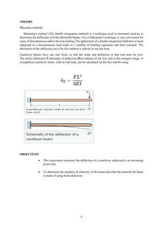
Cantilever beams have one end fixed, so that the slope and deflection at that end must be zero.
The elastic deflection δ and angle of deflection Ø(in radians) at the free end in the example image: A
(weightless) cantilever beam, with an end load, can be calculated (at the free end B) using:
OBJECTIVES
This experiment examines the deflection of a cantilever subjected to an increasing
point load.
To determine the modulus of elasticity of the beam and what the material the beam
is made of using beam delection.
3. 3
Converting the masses used in the experiments to loads
Mass (grams) Load (newtons)
100 0.98
200 1.96
300 2.94
400 3.92
500 4.90
PROCEDURES
1. The width and depth of the aluminium, brass and steel were measured by vernier gauge.
2. The values were recorded to the results tables for each material and used them to calculate the
second moment area.
3. Clamps and knife edges from the backboard were removed.
4. One of the cantilevers was set up.
5. The digital dial test indicator was slide to the position on the beam.
6. A knife-edge hanger was slide to the position shown.
7. The frame lightly was tapped and the digital dial test indicator was zero using the ‘origin’ button.
8. The knife-edge was applied masses in the increments.
9. The frame lightly was tapped each time.
10. The digital dial test indicator were recorded for each increment of mass.
11. The procedure were repeated for the other two materials and filled in a new tables.
4. 4
RESULTS
material Brass
E value :1.05 x 10⁻¹⁶
Width b : 19.02 mm
I : 48.14 Depth d : 3.12 mm
Mass (g) Actual deflection (mm) Theoretical deflection (mm)
0 0 0
100 -0.7 5.170 x 10²⁰
200 -1.27 1.034 x 10²¹
300 -1.93 1.551 x 10²¹
400 -2.55 2.068 x 10²¹
500 -3.09 2.585 x 10²¹
material aluminium
E value :6.9 x 10⁻¹⁹
Width b : 19.3 mm
I : 68.96 Depth d : 3.5 mm
Mass (g) Actual deflection (mm) Theoretical deflection (mm)
0 0 0
100 -0.93 5.492 x 10²²
200 -1.63 1.098 x 10²³
300 -2.46 1.684 x 10²³
400 -3.21 2.197 x 10²³
500 -4.15 2.746 x 10²³
material Steel
E value :2.07 x 10⁻¹⁶
Width b : 19.01 mm
I : 57.20 Depth d : 3.3 mm
Mass (g) Actual deflection (mm) Theoretical deflection (mm)
0 0 0
100 -0.34 2.207 x 10²⁰
200 -1.74 4.414 x 10²⁰
300 -1.05 6.621 x 10²⁰
400 -2.40 8.829 x 10²⁰
500 -3.70 1.104 x 10²¹
CALCULATIONS
Theoretical deflection
Formula =
𝑊𝐿3
3𝐸𝐼
Where:
W= load(N)
L = distance from support to position of loading (m)
E = young’s modulus for cantilever material (N/m2
)
I = second moment of area of the cantilevel (m4
5. 5
Calculation for Brass material
For mass 100g
=
(0.98)×(200)3
3(1.05 ×10⁻¹⁶)(38.14)
= 5.170 x 10²²
mm
For mass 200g
=
(1.96)×(200)3
3(1.05 ×10⁻¹⁶)(38.14)
=1.034 x 10²¹
mm
For mass 300g
=
(2.94)×(200)3
3(1.05 ×10⁻¹⁶)(38.14)
=1.551 x 10²¹
mm
For mass 400g
=
(3.92)×(200)3
3(1.05 ×10⁻¹⁶)(38.14)
=2.068 x 10²¹
mm
For mass 500g
=
(3.92)×(200)3
3(1.05 ×10⁻¹⁶)(38.14)
=2.585 x 10²¹
mm
Calculation for Aluminium material
For mass 100g
=
(0.98)×(200)3
3(6.9 ×10⁻¹⁷)(68.96)
=5.492 x 10²⁰
mm
For mass 200g
=
(1..96)×(200)3
3(6.9 ×10⁻¹⁷)(68.96)
6. 6
=1.098 x 10²¹
mm
For mass 300g
=
(2.94)×(200)3
3(6.9 ×10⁻¹⁷)(68.96)
=1.648 x 10²¹
mm
For mass 400g
=
(3.92)×(200)3
3(6.9 ×10⁻¹⁷)(68.96)
=2.197 x 10²¹
mm
For mass 500g
=
(4.90)×(200)3
3(6.9 ×10⁻¹⁷)(68.96)
=2.745 x 10²¹
mm
Calculation for Steel material
For mass 100g
=
(0.98)×(200)3
3(2.07 ×10⁻¹⁶)(57.20)
=2.207 x 10²⁰
mm
For mass 200g
=
(1.69)×(200)3
3(2.07 ×10⁻¹⁶)(57.20)
=4.414x 10²⁰
mm
For mass 300g
=
(2.94)×(200)3
3(2.07 ×10⁻¹⁶)(57.20)
=2.207 x 10²⁰
mm
8. 8
OBSERVATION
From the experiment:
a. Graph of deflection versus mass for all three beams.
0
1
2
3
4
5
6
7
0 gram 100 gram 200 gram 300 gram 400 gram 500 gram
Brass
Actual Deflection theoretical Deflection
0
1
2
3
4
5
6
7
8
0 gram 100 gram 200 gram 300 gram 400 gram 500 gram
Aluminium
Actual Deflection theoretical Deflection
9. 9
b. Comment on the relationship between the mass and the beam reflection.
The more load the higher the value of deflection. The result of the experiment is more accurate
than the result using the calculation based on theory .
c. Is there a relationship between the gradient of the line for each graph and the modulus of the
material?
For aluminium, the line for theoretical deflection is ascending and descending.
For brass, the line for actual deflection is just straight line.
For steel, the line for theoretical deflection is from bottom to ascending and descending.
d. Three practical application of a cantilever structure.
Steel.
Concrete.
Bridges.
0
2
4
6
8
10
12
0 gram 100 gram 200 gram 300 gram 400 gram 500 gram
Steel
Actual Deflection theoretical Deflection
10. 10
CONCLUSION
In deflection of a cantilever, aluminium beam has the largest deflection, followed by brass beam and
steel beam has smallest deflection. The beam deflection is directly proportional to mass applied to the
beam. The higher the modulus of material, the smaller the gradient of the line for each graph. The
equation predicted the behaviour of beam which is in linear relationship. The theoretical deflection is
always lower than the actual deflection. In deflection of a simply supported beam, aluminium beam has
significantly less deflection in simply supported beam than in cantilever. Deflection of beam is directly
proportional to mass applied to the beam. Deflection of beam increased exponentially with distance
form support to position of loading
REFERENCES
1. Donald P.Codute (2012). Structure Engineering (2nd
ed). Us
2. Braja M.Das (2011). Principles of structure engineering (9nd ed). British
3. Robert D.Holtz (2010). A Introduction to structure Engineering (2nd
ed). British.
4. Robert W.Day (2009). structure engineers handbook (2nd
ed). Us