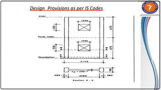
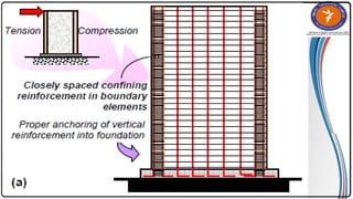
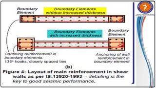
SHEAR
WALL
THEORY OF STRUCTURE- VI (AP-322)
COMPARISONS OF SHEAR WALL WITH CONVENTIONAL LOAD BEARING WALLS
Load bearing masonry is very brittle material. Due to different kinds of stresses
such as shear, tension, torsion, etc., caused by the earthquakes, the conventional
unreinforced brick masonry collapses instantly during the unpredictable and sudden
earthquakes!
The RCC framed structures are slender, when compared to shear wall concept of
box like three-dimensional structures. Though it is possible to design the earthquake
resistant RCC frame, it requires extraordinary skills at design, detailing and
construction levels, which cannot be anticipated in all types of construction
projects.
On the other hand even moderately designed shear wall structures not only more
stable, but also comparatively quite ductile. In safety terms it means that, during
very severe earthquakes they will not suddenly collapse causing death of people.
They give enough indicative warnings such as widening structural cracks, yielding
rods, etc., offering most precious moments for people to run out off structures,
before they totally collapse.
CLASSIFICATION OF SHEAR WALLS
•Simple Rectangular Types And Flanged Walls (Bar Bell Type)
•Coupled Shear Walls
•Rigid Frame Shear Walls
•Framed Walls With In Filled Frames
•Column Supported Shear Walls
•Core Type Shear Walls
SIMPLE RECTANGULAR TYPES AND FLANGED WALLS (BAR BELL TYPE)
Flanged shear walls are used extensively in moderate- and high-rise buildings to
resist lateral loads induced by earthquakes. The seismic performance of many
buildings is, therefore, closely linked to the behaviour of the reinforced concrete
walls. They must be carefully designed to provide not only adequate strength, but
also sufficient ductility to avoid brittle failure under strong lateral loads,
especially during an earthquake.
COUPLED SHEAR WALLS
When two or more shear walls are connected by a system of
beams or slabs, total stiffness exceeds the summation of
individual stiffness.
This is because the connecting beam restrains individual
cantilever action. Shear walls resist lateral forces up to 30–40
storeys Walls with openings present a complex problem to the
analyst.
Openings normally occur in vertical rows throughout the height of
the wall and the connection between wall cross-sections is
provided either by connecting beams which form part of the wall
or floor slab or a combination of both.
The terms ‘coupled shear walls’, ‘pierced shear walls’ and ‘shear
wall with openings’ are commonly described for such units.
If the openings are very small, their effect on the overall state of
stress in the shear wall is minimal.
Large openings have a pronounced
effect and if large enough result in a
system in which frame action
predominates.
The degree of coupling between two
walls separated by a row of openings
has been expressed of geometric
parameter α (having a unit of 1/length)
which it gives a measure of relative
stiffness of beams with respect to that of
walls. When αH exceeds 13, the walls
may be analysed as a single
homogenous cantilever. When αH<0.8
the wall may be analysed as the separate
cantilever, 0.8<αH<13, the stiffness of
connecting beam must be considered.
RIGID FRAME SHEAR WALLS
A rigid frame is combined with shear walls, the resulting structure is very much
stiffer so that its height probability may extend up to 50 stories or more
A rigid frame is combined with shear walls, the resulting structure is very much
stiffer so that its height probability may extend up to 50 stories or more
Buildings with masonry infill wall are the most common type of structures used for
multi-storey constructions in the developing countries.
Masonry Brick infill walls have been used in Reinforced concrete Frame structures
as interior and exterior partition walls. Infill walls now a day are considered to be
non-load bearing member. In the design and assessment of building, the infill walls
are usually treated as non- structural element and they are ignored in analytical
models because they are assumed to be non-beneficial to the structural response.
Reinforced concrete framed buildings with infills are usually analysed as bare
frame, without considering the strength and stiffness contributions of the infills.
However during wind and earthquake these infill walls contribute some response
of the structure and increase the strength and stiffness of the frame.
FRAMED WALLS WITH IN FILLED FRAMES
COLUMN SUPPORTED SHEAR WALLS
Reinforce Concrete Core Shear Wall is the most important structural component of
tall buildings in order to tolerate horizontal and vertical load. Reinforce Concrete
Core Shear Walls which are used in staircases and elevators are made up of some
shear walls that make box shape sections. Cores have different shapes such as I ،C ،
and 2C.They are very similar to rectangular shear walls in flexural characteristics,
but difference between core and shear wall is their torsion resistance.
CORE TYPE SHEAR WALLS
METHODS OF DESIGN OF SHEAR WALL
There are three types of design methods
1.Segmented shear wall method
2.Force transfer –ground openings method
3.Perforated shear wall method
SEGMENTED SHEAR WALL METHOD
The segmented shear wall method uses full height shear wall
segments that comply with ratio requirements and are usually
restrained against overturning by hold down devices at the
ends of each segment.
FORCE TRANSFER –GROUND OPENINGS METHOD
The second method—force transfer-ground openings method—considers the entire
shear wall with openings and the wall piers adjacent to openings are segments. The
method requires the forces around the perimeter of the openings to be analyzed,
designed, and detailed. With this method, the hold-down devices generally occur at
the ends of the shear wall, not at each wall pier, and special reinforcement around the
opening is often required. .
PERFORATED SHEAR WALL METHOD
•The third and newest method is the perforated shear wall method
which is an empirical approach that does not require special detailing
for force transfer adjacent to the openings. The perforated shear wall
method, however, specifically requires hold-down devices at each end
of the perforated shear wall.
DESIGNPROVISIONS AS PER IS CODES
General requirements
1. The thickness of any part of the wall shall not be less than 100 mm Reason : The
minimum thickness is specified as 100 mm to avoid
usually thin sections. Very Thin sections are susceptible to lateral instability in the
zones where inelastic cyclic loads may have to be sustained.
2. Shear wall shall be provided with reinforcement in the longitudinal and transverse
directions in the plane of the wall . The minimum reinforcement ratio shall be
0.0025 of the gross sectional area in each direction. This reinforcement shall be
distributed uniformly across the cross section of the wall.
Reason: Distribution of a minimum reinforcement uniformly across the height &
width of the wall helps to control the width of the inclined cracks that are caused
due to shear.
Design Provisions as per IS Codes
DESIGNPROVISIONS AS PER IS CODES
•
3. Boundary Elements Boundary elements are portions along the wall
edges that are strengthened by longitudinal and transverse reinforcement . Though
they have same thickness as that of the wall web, it is advantageous to provide them
with greater thickness.
Reason: Wall sections having stiff and well confined boundary elements develop
substantial flexural strength are less susceptible to lateral buckling & have better
shear strength & ductility in comparison to plane rectangular walls not having stiff &
well confined boundary elements .
4 Openings in walls : The shear strength of a wall containing openings should be
checked along critical planes that pass through openings.
Reason : An opening in a shear wall causes high shear stresses in the region of the
wall adjacent to it. Hence, it is necessary to check such regions for adequacy of
horizontal shear reinforcement in order to prevent a diagonal tension failure due to
shear.
•
•
•
Reinforcement shall be provided along the edges of the openings in the walls . The
area of the vertical and horizontal bars should be such as to equal that of the
respective interrupted bars. The vertical bars should extend for the full storey height.
The horizontal bars should be provided with development length in tension beyond
the sides of the opening .
Discontinuous Walls :
Columns supporting discontinuous walls shall be provided with special confining
reinforcement as per IS :4326 over their full height. The column reinforcement shall
be extended into the wall for a distance equal to the development length of the
largest longitudinal bar in the column.
•
Reason : Columns supporting discontinued shear walls may be
subjected to significant axial compression and may have to undergo extensive
inelastic deformations. Hence , they have to be adequately confined over their full
length to ensure good ductility.
L-3 Shear Wall Part-2.ppt

L-3 Shear Wall Part-2.ppt

  • 1.
  • 2.
    COMPARISONS OF SHEARWALL WITH CONVENTIONAL LOAD BEARING WALLS Load bearing masonry is very brittle material. Due to different kinds of stresses such as shear, tension, torsion, etc., caused by the earthquakes, the conventional unreinforced brick masonry collapses instantly during the unpredictable and sudden earthquakes! The RCC framed structures are slender, when compared to shear wall concept of box like three-dimensional structures. Though it is possible to design the earthquake resistant RCC frame, it requires extraordinary skills at design, detailing and construction levels, which cannot be anticipated in all types of construction projects. On the other hand even moderately designed shear wall structures not only more stable, but also comparatively quite ductile. In safety terms it means that, during very severe earthquakes they will not suddenly collapse causing death of people. They give enough indicative warnings such as widening structural cracks, yielding rods, etc., offering most precious moments for people to run out off structures, before they totally collapse.
  • 3.
    CLASSIFICATION OF SHEARWALLS •Simple Rectangular Types And Flanged Walls (Bar Bell Type) •Coupled Shear Walls •Rigid Frame Shear Walls •Framed Walls With In Filled Frames •Column Supported Shear Walls •Core Type Shear Walls
  • 4.
    SIMPLE RECTANGULAR TYPESAND FLANGED WALLS (BAR BELL TYPE) Flanged shear walls are used extensively in moderate- and high-rise buildings to resist lateral loads induced by earthquakes. The seismic performance of many buildings is, therefore, closely linked to the behaviour of the reinforced concrete walls. They must be carefully designed to provide not only adequate strength, but also sufficient ductility to avoid brittle failure under strong lateral loads, especially during an earthquake.
  • 5.
    COUPLED SHEAR WALLS Whentwo or more shear walls are connected by a system of beams or slabs, total stiffness exceeds the summation of individual stiffness. This is because the connecting beam restrains individual cantilever action. Shear walls resist lateral forces up to 30–40 storeys Walls with openings present a complex problem to the analyst. Openings normally occur in vertical rows throughout the height of the wall and the connection between wall cross-sections is provided either by connecting beams which form part of the wall or floor slab or a combination of both. The terms ‘coupled shear walls’, ‘pierced shear walls’ and ‘shear wall with openings’ are commonly described for such units. If the openings are very small, their effect on the overall state of stress in the shear wall is minimal.
  • 6.
    Large openings havea pronounced effect and if large enough result in a system in which frame action predominates. The degree of coupling between two walls separated by a row of openings has been expressed of geometric parameter α (having a unit of 1/length) which it gives a measure of relative stiffness of beams with respect to that of walls. When αH exceeds 13, the walls may be analysed as a single homogenous cantilever. When αH<0.8 the wall may be analysed as the separate cantilever, 0.8<αH<13, the stiffness of connecting beam must be considered.
  • 7.
    RIGID FRAME SHEARWALLS A rigid frame is combined with shear walls, the resulting structure is very much stiffer so that its height probability may extend up to 50 stories or more A rigid frame is combined with shear walls, the resulting structure is very much stiffer so that its height probability may extend up to 50 stories or more
  • 8.
    Buildings with masonryinfill wall are the most common type of structures used for multi-storey constructions in the developing countries. Masonry Brick infill walls have been used in Reinforced concrete Frame structures as interior and exterior partition walls. Infill walls now a day are considered to be non-load bearing member. In the design and assessment of building, the infill walls are usually treated as non- structural element and they are ignored in analytical models because they are assumed to be non-beneficial to the structural response. Reinforced concrete framed buildings with infills are usually analysed as bare frame, without considering the strength and stiffness contributions of the infills. However during wind and earthquake these infill walls contribute some response of the structure and increase the strength and stiffness of the frame. FRAMED WALLS WITH IN FILLED FRAMES
  • 9.
  • 10.
    Reinforce Concrete CoreShear Wall is the most important structural component of tall buildings in order to tolerate horizontal and vertical load. Reinforce Concrete Core Shear Walls which are used in staircases and elevators are made up of some shear walls that make box shape sections. Cores have different shapes such as I ،C ، and 2C.They are very similar to rectangular shear walls in flexural characteristics, but difference between core and shear wall is their torsion resistance. CORE TYPE SHEAR WALLS
  • 11.
    METHODS OF DESIGNOF SHEAR WALL There are three types of design methods 1.Segmented shear wall method 2.Force transfer –ground openings method 3.Perforated shear wall method
  • 12.
    SEGMENTED SHEAR WALLMETHOD The segmented shear wall method uses full height shear wall segments that comply with ratio requirements and are usually restrained against overturning by hold down devices at the ends of each segment.
  • 13.
    FORCE TRANSFER –GROUNDOPENINGS METHOD The second method—force transfer-ground openings method—considers the entire shear wall with openings and the wall piers adjacent to openings are segments. The method requires the forces around the perimeter of the openings to be analyzed, designed, and detailed. With this method, the hold-down devices generally occur at the ends of the shear wall, not at each wall pier, and special reinforcement around the opening is often required. . PERFORATED SHEAR WALL METHOD •The third and newest method is the perforated shear wall method which is an empirical approach that does not require special detailing for force transfer adjacent to the openings. The perforated shear wall method, however, specifically requires hold-down devices at each end of the perforated shear wall.
  • 15.
    DESIGNPROVISIONS AS PERIS CODES General requirements 1. The thickness of any part of the wall shall not be less than 100 mm Reason : The minimum thickness is specified as 100 mm to avoid usually thin sections. Very Thin sections are susceptible to lateral instability in the zones where inelastic cyclic loads may have to be sustained. 2. Shear wall shall be provided with reinforcement in the longitudinal and transverse directions in the plane of the wall . The minimum reinforcement ratio shall be 0.0025 of the gross sectional area in each direction. This reinforcement shall be distributed uniformly across the cross section of the wall. Reason: Distribution of a minimum reinforcement uniformly across the height & width of the wall helps to control the width of the inclined cracks that are caused due to shear.
  • 17.
  • 21.
    DESIGNPROVISIONS AS PERIS CODES • 3. Boundary Elements Boundary elements are portions along the wall edges that are strengthened by longitudinal and transverse reinforcement . Though they have same thickness as that of the wall web, it is advantageous to provide them with greater thickness. Reason: Wall sections having stiff and well confined boundary elements develop substantial flexural strength are less susceptible to lateral buckling & have better shear strength & ductility in comparison to plane rectangular walls not having stiff & well confined boundary elements . 4 Openings in walls : The shear strength of a wall containing openings should be checked along critical planes that pass through openings. Reason : An opening in a shear wall causes high shear stresses in the region of the wall adjacent to it. Hence, it is necessary to check such regions for adequacy of horizontal shear reinforcement in order to prevent a diagonal tension failure due to shear.
  • 22.
    • • • Reinforcement shall beprovided along the edges of the openings in the walls . The area of the vertical and horizontal bars should be such as to equal that of the respective interrupted bars. The vertical bars should extend for the full storey height. The horizontal bars should be provided with development length in tension beyond the sides of the opening . Discontinuous Walls : Columns supporting discontinuous walls shall be provided with special confining reinforcement as per IS :4326 over their full height. The column reinforcement shall be extended into the wall for a distance equal to the development length of the largest longitudinal bar in the column. • Reason : Columns supporting discontinued shear walls may be subjected to significant axial compression and may have to undergo extensive inelastic deformations. Hence , they have to be adequately confined over their full length to ensure good ductility.