SlideShare a Scribd company logo
John Benavides 1
John Benavides
EML 4535C
Summer 2015
CADCAM FINAL REPORT
CADCAM Midterm Section: Modeling a Ratch-N-Lock
Pliers
1. Project Goals
Every engineer should have at least some basic understanding of how a modeling program
operates. NX 8.5 is a common computer aided design (CAD) software, created by Siemens,
which engineers can use to create models, tools, and objects in. The goal of building a Ratch-N-
Lock Pliers from this class, is to learn the basic steps into designing and creating objects inside
this modeling program. For the final project using this Ratch-N-Lock Pliers, a finite element
model (FEM) was created after the modeling of the Ratch-N-Lock Pliers where complete. A 10
pound force was applied to handle section of the Pliers, and a piece of nylon was inserted into
the Jaw section to so that the force may be applied onto the nylon. This shall determine the load
forces on this object created.
2. Background/Description
Ratch-N-Lock Pliers is designed to both clam and lock onto a wide
array of object sizes. It is a combination of pliers, an adjustable
wrench, and a vise-grip. It can automatically adjust to any size nut,
bolt, or pipe with the adjustable sliding handle. The locking nob on
the back of the Pliers is meant to lock or unlock the Ratch-N-Lock
Pliers. This locking mechanism will cause the pliers to act like a
vise-grip where it can be used to pick up objects or hold the desired
object in place. Once the handles are squeezed together, the jaws of
the Ratch-N-Lock Pliers will lock around the object that is desired
and can then be used to loosen or tightened the object desired. The
shape and teeth of the jaw are designed to clamp and grip any size
bolt, nut, or fastener, this combined with the adjustable jaw position
makes this a multifunction tool.
Figure #1: Ratch-N-Lock Pliers
John Benavides 2
Figure #2: Link Figure #3: Locking Block
Figure #4: Sliding Block Figure #5: Locking Nob
Figure #6: Jaw Figure #7: Handle
Figure #8: Jaw Handle
John Benavides 3
3.1 Link
Step #1.1: Started a new sketch from XY plane datum, then create
the two latches/connection points to the handle and hole above with
respect to the XY datum.
Step #1.2: Created reference circles for teeth. Use
pattern curve to replicate teeth once one tooth is
created.
Step #1.3: Finished making body of the link with
the line tool, arc tool, and tangent constraints.
John Benavides 4
Step #1.4: Extrusion the main body
symmetrically 1/16”. Extrude the out connection
point diameter symmetrically by 1/8”. For the
inner connection extrude the top half 1/8” +
1/16” and the bottom half -1/8” - 1/32”. Link
complete.
3.2 Locking Block
Step #2.1: Started a new sketch from XY
plane datum, use the line and arc tool to create
the generic shape for the locking block
Step #2.2 Use the arc by center tool and
create two reference arcs (brown path).
Created one tooth with the proper length
and angle, then use pattern curve to create
the row of teeth around that portion of the
curve.
John Benavides 5
Step #2.3: Extrude the main body
symmetrically over the datum by 1/8”.
Step ##2.4: Extrude the connection point with
two different depths: the top half having a depth
of 1/8”+1/16” and the bottom half being -1/8”-
1/32” from the datum.
Step ##2.6: Use the edge blend tool to round
the “lip” of the locking block.
John Benavides 6
Step ##2.7: Locking Block Complete
3.3 Sliding Block
Step #3.1: Started a new sketch from XY plane datum, draw
shape of sketch with straight line tool. Give angle constrains
to the inner connection points.
Step #3.2: Add a circle that is tangent to the left and
upper portion of the box in order to fillet the top portion
of the sliding block easier. Then used the fillet tool to
trim the edges within the box to the appropriate radius.
John Benavides 7
Step #3.3: Extrude the body symmetrically by 1/8”. Sliding
Block complete.
3.4 Locking Nob
Step #4.1: Started a new sketch from XY
plane datum, create the inner rings of the
locking nob. Use the “Make Corner”
command to make the mouth of the
Locking Nob symmetric over the X axis.
Step #4.2: Use the fillet tool to
create the mouth of the locking nob
John Benavides 8
Step #4.3: Extrude body to the largest length
using the symmetric value and a distance of
3/16”.
Step #4.4: With a new sketch, draw circles on the XY
plan to create the different depth layers of the Locking
Nob. Extrude 3/32” of depth for both the top and bottom
half of the locking block using the subtraction Boolean
command. Repeat with symmetric extrusions of 1/8” and
then 1/8” +1/32” -1/8” -1/16” for the top and bottom
middle layer respectfully.
Step #4.5: Next Use the chamfer tool to create a 1/64”
rounded edge between the outer circle and middle circle.
John Benavides 9
Step #4.6: Use the chamfer tool again to create a 3/64”
rounded edge between the top and bottom faces of the
Nob.
Step #4.7: Finally create a 1/64” around the side of the
Nob.
Step #4.8: Use the offset curve to replicate the outer ring 1/64”
inward. Draw the teeth, making sure are the arc center command
is off and the teeth is vertically constrained and has a midpoint
constrain to the center of the XY plan datum. Make the slanted
slops of the teeth have equal lengths constrains. Use the parallel
feature to constrain the sides of the teeth.
John Benavides 10
Step #4.9: Create two reference lines from
the teeth/gap to the XY datum. Make sure
you close the loop for the teeth extrusion.
Step #4.10: Use the pattern feature tool create the
row of teeth. Select the teeth extrusion and apply
the pattern around one half of the Locking Nob
Mouth. Make sure that that specific vector and
point is the Z axis and the origin respectfully.
Step #4.11: Locking Nob Complete.
John Benavides 11
3.5 Jaw
Step #5.1: Started a new sketch from XY
plane datum with the generic sketch using
the profile line and arc tool. Constrain
accordingly using inferred dimensions
and radius constrains.
Step #5.2: Repeat same step as above for
the inner components of the Jaw. Then use
Region Boundary Curve extruding the
main body of the Jaw symmetrically by
9/32”.
Step #5.3: Next, the lip was extruded
symmetrically by 3/8”. Make sure that
the “None” is selected for Boolean.
John Benavides 12
Step #5.4: edge blend the nose with radiuses of 1/16”
and ¼” on the top and bottom halves respectfully.
Step #5.5: Use the inferred
Datum plan command to create a
new plan that is normal to the
reference line.
Step #5.6: Create two parallel
lines and constrain the parallel
line to have an angle of 6° from
your new plan X-axis.
John Benavides 13
Step #5.7: Create a closed loop
with the two parallel lines. Use
the subtractive extrusion. After
the extrusion, use the mirror
feature to copy the tapered cuts
to the bottom side of the Jaw.
Step #5.8: Unit the Jaw body and the lip of
the Jaw using the unit tool.
Step #5.9: Now to create the
hole going inside the body of the
Jaw, create a circle with
diameter of 9/8”. Create a line
that is perpendicular to the bass
of the Jaw from the circle was
then created. Close this loop
John Benavides 14
Step #5.10: Use the
subtracted Boolean
command, extrude
symmetrically 1/8”
Step #5.11: Use the
chamfer tool to angle
the edges of the Jaw.
Step #5.12: Start a new sketch and drawing
the teeth in the sketch with a closed loop.
Make sure you are along the centerline body
of the Jaw since the Jaw is tapered. Use the
Subtraction Extrusion, the linear pattern
feature and the instant geometry feature to
create the pattern of teeth.
John Benavides 15
Step #5.12: Jaw Complete.
3.6 Handle
Step #6.1: Open the Handle file that was initially given.
Create four new datum plan that is inferred from the XZ
plane in the negative y direction at 2, 2.2, 2.52, and 6.1
inches.
Step #6.2: On the first plane, the intersection point needs to be found
using the intersection tool and select the curve line along the Handle. This
will create a marker showing the intersection point of the curved line on
the Handle and the datum selected (blue plus). Turn it into a reference
point.
John Benavides 16
Step #6.3: Make the box shape on the plane and
use the fillet tool, inferred dimensions tools and
midpoint constraint tool.
Step #6.4: Repeat Step #6.3 on the next three datum
planes.
Step #6.5: Create a new sketch on the original XY plan. Use the
straight line tool and the arc tool to connect the left most
rectangles. Use the Fillet tools to make sure the left guideline is
tangent to the body of the Handle.
John Benavides 17
Step #6.6: Use the swept tool to create the rubber section of the
Handle. Make sure that tangent curve is selected and click on
the top section of each created rectangle. After each rectangle is
selected, click on “add new set” until all four rectangles are
picked. For the Guided selective curve, pick both the left and
right guidelines, and make sure that a new set was clicked after
selecting one of the sides. Use the cubic interpolation to make
sure the Handle is smooth if the linear interpolation produces an
undesired amount of sharpness along the curve of the Handle.
Step #6.7: Use the edge blend tool to finish the ascetic portion of
the Handle on both the top and bottom faces of the Handle.
Hallow out the Handle that was just created with the swept tool.
Use the extrude tool with the symmetric value and subtracted
Boolean selected.
John Benavides 18
Step #6.7: Back Handle Complete
3.7 Jaw Handle
Step #7.1: Open the pre-
loaded Jaw Handle file and
start a new sketch from XY
plane datum. Draw the shape
of the Jaw Head using the line
and arc tool. Constrain
properly using inferred and
angular dimensions.
John Benavides 19
Step #7.2: Extrude the top portion of the Jaw
Head symmetrically by .28” using the region
boundary option. Extrude the Middle section of
the Jaw Head symmetrically by .345” using the
region boundary option as well.
Step #7.3: To tapper the Jaw Head, create a new
inferred datum at the reference line.
Step #7.4: Create two parallel lines that are 5
degrees below the x plane. Use the point on
curve constraint to ensure the parallel lines
are in referenced to the y axis on this datum.
Step #7.5: Use the subtract Boolean
command when extruding, then use
the mirror feature to copy the tapper
work to the other side of the Jaw.
John Benavides 20
Step #7.6: Unit the mouth of the Jaw to the Jaw Handle.
Step #7.7: Select a new on curve datum plan and place three datum
plans in there approximant location along the line. For the final
datum. Place it -0.3 inches away from the end of the handle
Step #7.8: Just like the Handle portion of this project,
draw the appropriate figure on the first datum along the
handle. Use the intersect point tool to place the reference
point on the datum and the curve, and use the
rectangular, fillets and constraints where needed.
John Benavides 21
Step #7.9: Repeat Step #7.8: on the second (2nd
) datum and fourth
(4th
) datum. For the third datum (3rd
), project the whole sketch
from the first (1st
) datum onto the third (3rd
) datum.
Step #7.10: Now use the swept tool to
pick each section along the handle. Use
the connected curve and pick the top
line for each rectangular profile. Click
on “add new set” after each rectangular
is selected. For the guide curve, select
the left side with the tangent curve. For
the right, use the single curve and cubic
interpolation to smooth out the handle.
Step #7.11: To create the hole in the handle and the slot,
extrude and use the subtract Boolean command where
needed. Edge blend where deemed appropriate.
John Benavides 22
Step #7.11: Jaw Handle Complete.
4. Assembly & Drafting
4 .1 Assembly
Step #A.1: Load the Jaw Handle, Jaw, and the
handle pieces. Fix the Jaw Handle on the origin.
John Benavides 23
Step #A.2: Use assembly constraint and the touch align
command to align the inner portion of the Jaw to the Jaw
Handle.
Step #A.3: Then use the center and 2 to 2 option command
to align the Jaw to the Jaw Handle.
John Benavides 24
Step #A.4: Next to align the Jaw and handle constrain the
two holes for each object with the touch align and infer
center/axis operation selected.
Step #A.5: To align the holes along the z axis
properly, use the center assembly constraint and
the 2 to 2 option to pick the faces of the Jaw and
the Handle.
Step #A.5.2: When aligned
John Benavides 25
Step #A.6: Next add the Link,
Locking Nob, and Locking
Block into the assembly.
Constrain the Link with the
Touch Align and Infer
Center/axis option to the Pre
made “metal” portion of the
handle file.
Step #A.6.2: Repeat Step #A.6: for the
Locking Nob
Step #A.6.3: Repeat Step #A.6: for the
Locking Block
John Benavides 26
Step #A.7: Use the touch
align to attach the other
part of the Link to the Jaw
Handle slit wth the prefer
touch option.
Step #A.8: Use the distance
assembly constraint and select the
centerline of both the arc at the
top of the slit and the handle nob
to constrain it approximately .1”
away from the centerline.
Step #A.9: Add the Sliding Block and use
the touch align constraint to place the
block against the back face of the Jaw
Handle.
John Benavides 27
Step #A.10: Use the
center constrain and the 2
to 2 option to align the
Sliding Block to the
Handle
Step #A.11: Use the touch
to align and preferred
touch option to align the
Sliding block to the
Handle so that the
pivoting mechanism will
work. Note that the
objects wont look
perfectly aligned but as
long as the handle can
move while keeping the
connection together then the alignment was successful.
John Benavides 28
Step #A.12: If the link slips
out of the slit of the Jaw
handle, use another distance
constraint and select the
centerline of the cylindrical
face at the bottom of the slit.
John Benavides 29
Step #A.13: Final Assembly Complete-Side By Side view of Original Ratch-N-Lock Pliers
John Benavides 30
4 .2 Part Drafting
Choose ONE part to create a drafting. The drafting should include at least 2 base views, 1
section view, and proper amount of dimensions.
John Benavides 31
5. FEM Model Overview
The following is a detailed section of the steps taken to create the FEM modle for the Ratch-N-
Lock. The purpose of the FEM model is to create an analysis of forces that can be applied to the
Ratch-N-Lock and what forces the Pliers will experience when given certain conditions. For this
project, a static analysis was performed by creating the FEM to squeeze down on a nylon bar.
With this simply movement, an analysis of the forces that are applied to the connection points,
handle, and Jaw can be analyzed visual in FIGURE #9 below. Using 1,2, and 3-D meshes,
different connections types (pin , ball joints, and glue to be exact) where mimicked, in order to
secure the Pliers properly After creating the connection joins, the proper material, resistance, and
forces where applied appropriately. Hand calculations will be referenced in the Appendix that
will support the FEM calculations and show an approximant error between the two calculations.
Figure #9: FEM Figures of Ratch-N-Lock
6. Idealized Part
Step #1. FEM Open applicable file to commence
finite element model (FEM). Start a
new simulation. Select Upper, Jaw
Handle, and Connection_Bar.
John Benavides 32
Step #2. FEM Select the Jaw Handle, and
make sure the Progressive
strategy option is selected.
Click on the
“Automatically create Face
Pairs.” This will create a
midsurface for the Jaw
Handle. After applying the
command, repeat for the
connection bar.
Step #3. FEM For the Jaw, we will split it into
two different sections along the
XY plane. Pick the “New Plane”
tool option then the XY plane.
Notice the line in the running in
the center Jaw.
John Benavides 33
Step #4. FEM Now to
split the
jaw handle,
select the
split body
command,
select both
the Jaw
Handle and
the mid-
surface of
the Jaw
Handle,
under the
tool option select “New Plane” and “on curve is selected. Use the single
body line curve selection to choose the proper curve along the Jaw Handle.
Finally made sure the plan is at 0 distance.
Step #5. FEM In FEM, select the 3D
tetrahedral Mesh with the
“CTETRA(4) type and
element size of 0.075. Select
the Lower Jaw, Handle,
Stopping Block, and solid
Jaw Handle.
John Benavides 34
Step #6. FEM Now repeat the same steps as above for half of the Upper Jaw. Make sure only
half of the jaw
is selected. Go
to Insert,
Element, copy
and reflect the
mesh along the
XY plan.
Step #7. FEM Blend and merge the two
meshes together.
Step #8. FEM Turn on the internal
display nodes of the
Upper Jaw by selecting
the mesh profile of the
Jaw, edited display then
select, Display Internal
Element Edges.
TABULATED CHARACTERISTICS FOR MESH DATA
1D CBAR Between
Jaws
1D CBAR Between
Lower Jaw and
Handle
1D CBAR Between
Handle and Link
Fore Sections 1D
CBAR
Radius=0.0625” Radius=0.15625” Radius=0.0625”
Materials 1D CBAR Nylon Steel Steel
John Benavides 35
7. FEM Assembly
Step #9. FEM Now 2D mesh the connection bar and Jaw Handle
with the CQUAD4 type and with an element size
off 0.05 and 0.075 respectively.
Step #10. FEM Extrude a 2D mesh by inserting an
element, and extrude. Extrude in both
the +z and –z direction.
Step #11. FEM Insert a 1D mesh node in between the mouth
of the Jaws by selecting Insert, Node, and
Node between Nodes, with the Between Two
Nodes type selected. Make sure that the two
middle nodes of each Jaw is selected. Give
the radius of the bar 0.0625 inches.
John Benavides 36
Step #12. FEM Start with 2D
mesh of then
link. Insert a
node at the
center of the
bottom hole of
link. Make sure
the inferred
point is selected
so the circle of
the polygon can be selected. Create two nodes at the center.
Step #13. FEM Go to the
1D
connection
tab, change
the element
type to
RBE2.
Select only
one node in
the middle
for the
source. For the Target Node, select each corner of the mesh within the hole.
Step #14. FEM For the
handle,
repeat the
same
steps as
above.
John Benavides 37
Step #15. FEM Both 1D spider meshes: RBE2 Link (red)
RBE2 Handle (yellow).
Step #16. FEM To connect
the meshes,
insert and
create a new
element.
Select the
CBUSH
type, and
select both
of the nodes
in the
middle of the 1D mesh.
Step #17. FEM Now
create
two
center
Node
between
the
handle and link like in STEP #14. Also create a node at the top and the
bottom of the handle holes
John Benavides 38
Step #18. FEM Now create the new
spider connection
(RBE2) in the middle
of the link. Make
sure RBE2 is
selected.
Step #19. FEM Repeat
the last
step to
create the
spider
mesh
between
the holes
in the
handle.
Step #20. FEM Now connect the spider meshes between the handles. Insert,
create element and select the CBAR type element. Turn off
the link spider to ensure the 2nd
Node that hasn’t been used
is selected.
John Benavides 39
Step #21. FEM Connect the mesh between the
link and the handle. Insert,
element, create, CBUSH. Make
sure to create a new mesh
destination. Select both node in
the middle of the spider mesh.
Step #22. FEM Create spider
mesh between
the lower Jaw
and the handle.
Step #23. FEM Select the two
nodes that was just
created for the
lower jaw. Make
sure to create two
nodes in the center
of the handle.
Step #24. FEM Create the spider mesh at the lower jaw
as before. To select the nodes along the
edge of the jaw you can use the feature
edge node drop down option. Rename
the Destination collector to Lower Jaw.
John Benavides 40
Step #25. FEM To connect the lower jaw
spiders, create a pin.
Insert, element, CBAR,
and change the collector
name since it’s a new
collector dimension
within the Ratch-N-Lock
Pliers.
Step #26. FEM To create the
spider mesh
inside the
handle,
change the
drop down
section
method to
“Feature
Angle
Nodes” when
selecting the
target nodes.
This will select the cylindrical surface of the handle. Put the destination ion
the handle section.
John Benavides 41
Step #27. FEM To connect the Lower Jaw and
Handle, Insert element, create,
CBUSH, change destination to
the 1st
collector and create a new
mesh. Select the two nodes in
the middle spider mesh (yellow).
Step #28. FEM Create a ball join between Stopping
block and Handle. Insert node. Click in
middle between the handle and Stopping
black and make two nodes. Make sure
that Z=0.
Step #29. FEM Create a spider
mesh on the
nodes. Select
RBE2 and select
the destination
to the Handle.
Select 4 nodes
along the edge
of the handle
face.
John Benavides 42
Step #30. FEM Repeat for the Stopping block change the
section method to “Feature Angle Nodes”
and change the angle to 5°.
Step #31. FEM Now connect using
CBUSH like Step
#27. Make sure to
create a new
destination of the
CBUSH.
Step #32. FEM To define the
degrees of
freedom, for the
CBUSH, right
click, then edit
(monkey wrench),
click on edit
again.
John Benavides 43
Step #33. FEM Repeat for the 2nd
CBUSH on the handle
to stopping block.
Step #34. FEM For shell thickness, right click on the shell
of the link, edit and edit again, change the
default thickness to 0.125” inches and the
material to “steel”.
Step #35. FEM Repeat for the shell of the handle
with thickness of 0.375”.
John Benavides 44
Step #36. FEM Repeat for the CBAR that is in between
the mouth of the Jaws by making the
material “nylon.”
Step #37. FEM Change the radius of the pin
connecting the Handle to the
Link to 0.0625”.
Step #38. FEM Change the
radius of the
pin
connecting
the Handle
to the
Lower Jaw
to 0.15625”.
John Benavides 45
TABULATED CHARACTERISTICS FOR MESH DATA
8. FEM Model Check
Step #39. FEM Use the element
edge to check
the bottom
connection
surface of the
Jaw Handle.
Now “glue” the
3D mesh and the
2D mesh
together along the Jaw Handle. If the normal direction is note facing twords
tteh 3D mesh of the Jaw Handle reverse the direction of the coresponding to
ensure the entire face is in the proper normal direction.
Fore Sections 1D
CBAR
Radius=0.0625” Radius=0.15625” Radius=0.0625”
Materials 1D CBAR Nylon Steel Steel
CBUSH Pin/Hinge Joints
(Handle Holes, Handle to
Link, Link to Jaw Handle)
CBUSH Ball Joints
(Sliding Block to Handle)
Stiffness 10e8 DOF 1-5
Free for DOF 6
10e8 DOF 1-3
Free for DOF 4-6
John Benavides 46
Step #40. FEM Check the joint connections with “Show adjacent” command. This is to
ensure that the connections made early are in the proper order and connected
properly to the respected section of the pliers. For the Pins
John Benavides 47
Step #41. FEM Repeat the above step for the Sliding Block
9. SIM Glue and Contact
Step #42. FEM In SIM use the
Surface to
surface gluning,
with manual
option. Select
the Upper Jaw
as the source
region.
Step #43. FEM Select the Lower Jaw
Handle as the target
region.
John Benavides 48
Step #44. FEM Now we will create the
region first and select the
target or source region
later. Repeat on Jaw
Handle and lable g21.
Step #45. FEM Select the Lower Jaw Handle
and label g22.
Step #46. FEM Repeat and
lab the c11
(contact) for
the Jaw
Handle.
John Benavides 49
Step #47. FEM Repeat and
label c12 for
the lower Jaw.
Make sure to
select the inner
edge of the
lower Jaw.
Step #48. FEM Repeat and label c21 for
the back of the handle.
Step #49. FEM Repeat and label c22 for the
sliding block.
John Benavides 50
Step #50. FEM Now apply the appropriate source and target region for gluning all sections
appropriately. IE C21 for
source and C22 as target
region.
10. Loading and Support
Step #51. FEM Back to the Fem, go
to modified
coordinates under
nodes and selected
a nod on the end of
the handle that is on
the XY plan (ie 0 Z
coordinate).
Step #52. FEM Back to sim, place a
10 lb force on the
nod that has no z
cordinate and apply
the force twords the
Lower Jaw Handle.
John Benavides 51
Step #53. FEM Repeate and create an
opisode force on the
other handle to create
and equal and oposite
force reaction.
Step #54. FEM Apply a fixed
constraint to
the middle of
the nylon bar.
Step #55. FEM User define
constraint and
kill the DOF
#3 and select
points that are
not in line on
the handle
ends and the
Sliding Block.
This is to
ensure that the
SIM won’t
consider and
friction forces
along the
Sliding Block. While the SIM would run, extra constraints have been placed
John Benavides 52
through the entire FEM process in order to simplify the results and forces
that will act on the Pliers.
11. Results and Verification
Final Displacement
John Benavides 53
Stress Plot
Stress Plot at Desired Location
John Benavides 54
Calculations
The following work, steps, and information on the calculations where provide from
Dr P.Richard Zarda, and Shenghong Zhang. The FBD and work for the Pliers can be found in
the “Appendix” of the report.
From Dr. Zard’s Free Body Diagram, the N (contact force) and X1 (force in nylon rod), where
found. To find N, the Sliding Block was assumed to be slightly off axis compared to the rest of
the Pliers. The Sliding Block was assumed to be frictionless in order to make the math easier.
Two formulas where related that involve N and X1 to solve the system of equations and the Low
Jaw is the key to obtain the system of equations. First the moment was found on the Jaw Handle
that was created from the force at the end of the handle. This was used to get an approximate
location of the center of moment along the Lower Jaw Handle. The force was then projected
along the Perpendicular vector of the Lower Jaw to the connection point between the Lower Jaw
and Handle. From here, the moment was taken, using the projected 10 pound force on the lower
handle was using with the corresponding distance between the handle and Lower Jaw connection
to get EQ1. The moment was taken again this time with respect of the Lower Jaw and the nylon
rod. Again, the force was projected to correspond with the distance of moment between the
connections points, giving us EQ2. Below is the corresponding work done by hand.
John Benavides 55
Below is the math to find the Bending stress of the 2D shell with the assistance of Shenghong
Zhang work.
John Benavides 56
Compared with the true simulation value as provided by Shenghong Zhang (-22.57868), my
corresponding values have a percent error of 0.2%.
Error Table
X N1 σ (Bending stress)
Hand Cal 21.314 234.35 2268
NX 22.624 233.4 2150
Error% 6.1% .4% 5.2%
12. Summary
As with all other engineering programs, Siemens NX software is design to make the job of an
engineer more efficient, and with this particular software, the job of creating and testing models
is indeed, much easier with the program. Creating the Rach-N-Lock pliers for this project was a
great way to learn and develop modeling and simulation skills.
The CAD portion of the project was a success as each individual piece was design as close as
possible and show great similarity to the original specifications of each part of the Ratch-N-Lock
Pliers. The assembly portion also appears to be successful as the Ratch-N-Lock Pliers function
in a realistic mater after all constraints where made. Like the CAD section, the simulation
conducted was also a success. The final result forces, as seen in the “Results” section, have a
0.2% error compared to Shenghong Zhang baseline results. While improvements can always be
John Benavides 57
made to both the model and simulation, the results show that I have learned and been able to
implement the knowledge I have learned over this past semester.
The key point I learned in the simulation and testing phase for this project was to understand the
1, 2 and 3D meshes that were used to connect each part within the project. Making proper uses of
the meshes and where to implement them, is key to obtain real world results and understanding
what forces might be applied to the object and how well the Pliers can handle the forces.
Understanding how each mesh works, especially when multiple meshes are used to the same
corresponding apart, goes a long way into seeing how these set of pliers, and any other modeled
object, will move and work in the real world.
Coming into this class, I was not a big fan of modeling programs, in fact I push this class off
because I dislike modeling. While I can’t say I love modeling and I am definitely no expert in the
class, my skills and enjoyment of the class increased each day and I can say that I am
knowledgeable and skilled in the Siemens NX modeling software where I hope to be able to
apply the skills and techniques learned to future school and work projects.
13. Appendix
13.1. Appendix for CAD
My work was based on the original dimensions, PowerPoints, and YouTube videos
provided by Shenghong Zhang and this project would not have been successful without his
work and help over the course of this project:
Video Guides
https://www.youtube.com/watch?v=0DCReZr6XFo
https://www.youtube.com/watch?v=qbQvHvXd8us
https://www.youtube.com/watch?v=VBHkpem8ozQ
https://www.youtube.com/watch?v=RSINc9Rs_3A
https://www.youtube.com/watch?v=-mKbbBUzYvk
https://www.youtube.com/watch?v=IieGBiwYS6U
https://www.youtube.com/watch?v=_oUfKHxvu2M
PowerPoints/ Drafting Drawings.
https://webcourses.ucf.edu/courses/1106171/files/folder/Midterm%2520Project/Drawings/Handl
e?preview=45653096
John Benavides 58
https://webcourses.ucf.edu/courses/1106171/files/folder/Midterm%2520Project/Drawings/Jaw_
Handle?preview=45764692
https://webcourses.ucf.edu/courses/1106171/files/folder/Midterm%2520Project/Drawings?previe
w=45542626
https://webcourses.ucf.edu/courses/1106171/files/folder/Midterm%2520Project/Drawings?previe
w=45577458
https://webcourses.ucf.edu/courses/1106171/files/folder/Midterm%2520Project/Drawings?previe
w=45368629
https://webcourses.ucf.edu/courses/1106171/files/folder/Midterm%2520Project/Drawings?previe
w=45368628
https://webcourses.ucf.edu/courses/1106171/files/folder/Midterm%2520Project/Drawings?previe
w=45523538
Modeling a Ratch-N-Lock Pliers
http://www.homedepot.com/p/Unbranded-8-in-Ratch-N-Lock-Pliers-013320/204468378
13.2. Appendix for FEM
Video Guides
https://www.youtube.com/watch?v=zjH3TSk2A8c
https://www.youtube.com/watch?v=ieCi8QGkOLQ
https://www.youtube.com/watch?v=LdtVKi0U8PY
PowerPoints/ Drafting Drawings.
https://webcourses.ucf.edu/courses/1106171/discussion_topics/3143556
https://webcourses.ucf.edu/courses/1106171/files/folder/Lab%2520Handout?preview=46089783
https://webcourses.ucf.edu/courses/1106171/files/folder/Lab%2520Handout?preview=46162670
https://webcourses.ucf.edu/courses/1106171/files/folder/Lab%2520Handout?preview=46308168
https://webcourses.ucf.edu/courses/1106171/files/folder/Lab%2520Handout?preview=46541283
Hand Calculations from Dr P.Richard Zarda,
https://webcourses.ucf.edu/courses/1106171/files/folder/Final%2520Project/Hand%2520Calculat
ion?preview=46512590
John Benavides Sum 15 CAD Final Report

More Related Content

Viewers also liked

QA QC Engineer-Inspector NEW
QA QC Engineer-Inspector NEWQA QC Engineer-Inspector NEW
QA QC Engineer-Inspector NEWMilen Kurian
 
Hardkorowa prezentacja :)
Hardkorowa prezentacja :)Hardkorowa prezentacja :)
Hardkorowa prezentacja :)adenrath
 
Coś o Nowym Sączu
Coś o Nowym SączuCoś o Nowym Sączu
Coś o Nowym Sączuadenrath
 
Agricoltura sociale, altra economia e sviluppo locale
Agricoltura sociale, altra economia e sviluppo locale Agricoltura sociale, altra economia e sviluppo locale
Agricoltura sociale, altra economia e sviluppo locale Emanuele Messina
 
Shot List for Talisman (February 2017)
Shot List for Talisman (February 2017)Shot List for Talisman (February 2017)
Shot List for Talisman (February 2017)lydiasear1
 
Développer l'écosystème en France autour du Raspberry Pi
Développer l'écosystème en France autour du Raspberry PiDévelopper l'écosystème en France autour du Raspberry Pi
Développer l'écosystème en France autour du Raspberry PiAlan McCullagh
 
Film Posters Analysis
Film Posters AnalysisFilm Posters Analysis
Film Posters Analysislydiasear1
 
Programmation Open Bidouille Camp x84 du 26 mars 2016 - Courthézon, Vaucluse
Programmation Open Bidouille Camp x84 du 26 mars 2016 - Courthézon, VaucluseProgrammation Open Bidouille Camp x84 du 26 mars 2016 - Courthézon, Vaucluse
Programmation Open Bidouille Camp x84 du 26 mars 2016 - Courthézon, VaucluseAlan McCullagh
 
Cam scanner
Cam scannerCam scanner
Cam scannerjavisq
 
日本人はなぜ蕎麦を食べるときに音を出すのか
日本人はなぜ蕎麦を食べるときに音を出すのか日本人はなぜ蕎麦を食べるときに音を出すのか
日本人はなぜ蕎麦を食べるときに音を出すのかmatsuzakishu
 
Lecture 8 Leadership, Status and other Loose Ends
Lecture 8 Leadership, Status and other Loose EndsLecture 8 Leadership, Status and other Loose Ends
Lecture 8 Leadership, Status and other Loose EndsAlexandros Karakostas
 

Viewers also liked (16)

QA QC Engineer-Inspector NEW
QA QC Engineer-Inspector NEWQA QC Engineer-Inspector NEW
QA QC Engineer-Inspector NEW
 
ME220_Dynamics
ME220_DynamicsME220_Dynamics
ME220_Dynamics
 
Hpv ve ağız kanseri
Hpv ve ağız kanseriHpv ve ağız kanseri
Hpv ve ağız kanseri
 
Hardkorowa prezentacja :)
Hardkorowa prezentacja :)Hardkorowa prezentacja :)
Hardkorowa prezentacja :)
 
Coś o Nowym Sączu
Coś o Nowym SączuCoś o Nowym Sączu
Coś o Nowym Sączu
 
Agricoltura sociale, altra economia e sviluppo locale
Agricoltura sociale, altra economia e sviluppo locale Agricoltura sociale, altra economia e sviluppo locale
Agricoltura sociale, altra economia e sviluppo locale
 
Shot List for Talisman (February 2017)
Shot List for Talisman (February 2017)Shot List for Talisman (February 2017)
Shot List for Talisman (February 2017)
 
ME530_Linear Systems Theory
ME530_Linear Systems TheoryME530_Linear Systems Theory
ME530_Linear Systems Theory
 
Développer l'écosystème en France autour du Raspberry Pi
Développer l'écosystème en France autour du Raspberry PiDévelopper l'écosystème en France autour du Raspberry Pi
Développer l'écosystème en France autour du Raspberry Pi
 
Film Posters Analysis
Film Posters AnalysisFilm Posters Analysis
Film Posters Analysis
 
Programmation Open Bidouille Camp x84 du 26 mars 2016 - Courthézon, Vaucluse
Programmation Open Bidouille Camp x84 du 26 mars 2016 - Courthézon, VaucluseProgrammation Open Bidouille Camp x84 du 26 mars 2016 - Courthézon, Vaucluse
Programmation Open Bidouille Camp x84 du 26 mars 2016 - Courthézon, Vaucluse
 
Cam scanner
Cam scannerCam scanner
Cam scanner
 
Lecture 2 Social Preferences I
Lecture 2 Social Preferences ILecture 2 Social Preferences I
Lecture 2 Social Preferences I
 
日本人はなぜ蕎麦を食べるときに音を出すのか
日本人はなぜ蕎麦を食べるときに音を出すのか日本人はなぜ蕎麦を食べるときに音を出すのか
日本人はなぜ蕎麦を食べるときに音を出すのか
 
Lecture 8 Leadership, Status and other Loose Ends
Lecture 8 Leadership, Status and other Loose EndsLecture 8 Leadership, Status and other Loose Ends
Lecture 8 Leadership, Status and other Loose Ends
 
GPS
GPSGPS
GPS
 

Similar to John Benavides Sum 15 CAD Final Report

Vice Grip Soldiworks Project
Vice Grip Soldiworks ProjectVice Grip Soldiworks Project
Vice Grip Soldiworks ProjectMichael Lagalle
 
Bracket Exercise (Inventor)
Bracket Exercise (Inventor)Bracket Exercise (Inventor)
Bracket Exercise (Inventor)Andrew Aung
 
Rib_www.staff.city.ac.uk.pdfyhuhuhuiop; [p0=][
Rib_www.staff.city.ac.uk.pdfyhuhuhuiop; [p0=][Rib_www.staff.city.ac.uk.pdfyhuhuhuiop; [p0=][
Rib_www.staff.city.ac.uk.pdfyhuhuhuiop; [p0=][meckup
 
Cadcam mid term report
Cadcam mid term reportCadcam mid term report
Cadcam mid term reportJose Olvera
 
Sculpted skateboard fusion 360 rev2
Sculpted skateboard fusion 360 rev2Sculpted skateboard fusion 360 rev2
Sculpted skateboard fusion 360 rev2dsp39
 
4. How to build shed roof rafters
4. How to build shed roof rafters4. How to build shed roof rafters
4. How to build shed roof raftersicreatablesseo
 
How to assemble a sink base vanity 48 60
How to assemble a sink base vanity 48 60How to assemble a sink base vanity 48 60
How to assemble a sink base vanity 48 60Domain CabinetsDirect
 
ME430FinalReport (1)
ME430FinalReport (1)ME430FinalReport (1)
ME430FinalReport (1)Ivan Romano
 
Model and texture a photorealistic usb cable with maya and mental ray
Model and texture a photorealistic usb cable with maya and mental rayModel and texture a photorealistic usb cable with maya and mental ray
Model and texture a photorealistic usb cable with maya and mental raySandra Montoya
 
21 simple bend requiring correction in 2 planes
21 simple bend requiring correction in 2 planes21 simple bend requiring correction in 2 planes
21 simple bend requiring correction in 2 planesDePlaque
 
Tutorial 3 d printed phone case
Tutorial 3 d printed phone caseTutorial 3 d printed phone case
Tutorial 3 d printed phone casesoumyadeepm96
 
iMovr Omega Olympus Manual 12 24-15
iMovr Omega Olympus Manual 12 24-15iMovr Omega Olympus Manual 12 24-15
iMovr Omega Olympus Manual 12 24-15iMovR
 
DID Unit 2: Exercises
DID Unit 2: Exercises DID Unit 2: Exercises
DID Unit 2: Exercises MrLawler
 

Similar to John Benavides Sum 15 CAD Final Report (20)

Vice Grip Soldiworks Project
Vice Grip Soldiworks ProjectVice Grip Soldiworks Project
Vice Grip Soldiworks Project
 
Bracket Exercise (Inventor)
Bracket Exercise (Inventor)Bracket Exercise (Inventor)
Bracket Exercise (Inventor)
 
Rib_www.staff.city.ac.uk.pdfyhuhuhuiop; [p0=][
Rib_www.staff.city.ac.uk.pdfyhuhuhuiop; [p0=][Rib_www.staff.city.ac.uk.pdfyhuhuhuiop; [p0=][
Rib_www.staff.city.ac.uk.pdfyhuhuhuiop; [p0=][
 
ViceGripFem
ViceGripFemViceGripFem
ViceGripFem
 
Cadcam mid term report
Cadcam mid term reportCadcam mid term report
Cadcam mid term report
 
Cad cam lab 2016 2017
Cad cam lab 2016 2017Cad cam lab 2016 2017
Cad cam lab 2016 2017
 
TRU-FIT
TRU-FITTRU-FIT
TRU-FIT
 
FEA Final Project
FEA Final ProjectFEA Final Project
FEA Final Project
 
Sculpted skateboard fusion 360 rev2
Sculpted skateboard fusion 360 rev2Sculpted skateboard fusion 360 rev2
Sculpted skateboard fusion 360 rev2
 
Pinion mount
Pinion mountPinion mount
Pinion mount
 
4. How to build shed roof rafters
4. How to build shed roof rafters4. How to build shed roof rafters
4. How to build shed roof rafters
 
FEM Paper
FEM PaperFEM Paper
FEM Paper
 
How to assemble a sink base vanity 48 60
How to assemble a sink base vanity 48 60How to assemble a sink base vanity 48 60
How to assemble a sink base vanity 48 60
 
How to assemble a sink base vanity
How to assemble a sink base vanityHow to assemble a sink base vanity
How to assemble a sink base vanity
 
ME430FinalReport (1)
ME430FinalReport (1)ME430FinalReport (1)
ME430FinalReport (1)
 
Model and texture a photorealistic usb cable with maya and mental ray
Model and texture a photorealistic usb cable with maya and mental rayModel and texture a photorealistic usb cable with maya and mental ray
Model and texture a photorealistic usb cable with maya and mental ray
 
21 simple bend requiring correction in 2 planes
21 simple bend requiring correction in 2 planes21 simple bend requiring correction in 2 planes
21 simple bend requiring correction in 2 planes
 
Tutorial 3 d printed phone case
Tutorial 3 d printed phone caseTutorial 3 d printed phone case
Tutorial 3 d printed phone case
 
iMovr Omega Olympus Manual 12 24-15
iMovr Omega Olympus Manual 12 24-15iMovr Omega Olympus Manual 12 24-15
iMovr Omega Olympus Manual 12 24-15
 
DID Unit 2: Exercises
DID Unit 2: Exercises DID Unit 2: Exercises
DID Unit 2: Exercises
 

John Benavides Sum 15 CAD Final Report

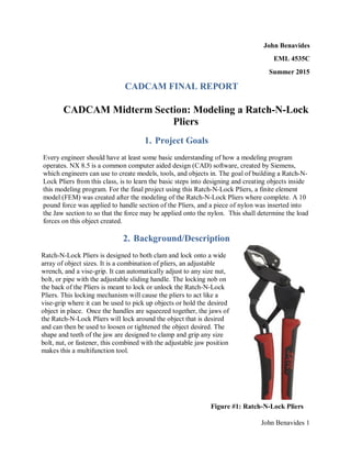
  • 1. John Benavides 1 John Benavides EML 4535C Summer 2015 CADCAM FINAL REPORT CADCAM Midterm Section: Modeling a Ratch-N-Lock Pliers 1. Project Goals Every engineer should have at least some basic understanding of how a modeling program operates. NX 8.5 is a common computer aided design (CAD) software, created by Siemens, which engineers can use to create models, tools, and objects in. The goal of building a Ratch-N- Lock Pliers from this class, is to learn the basic steps into designing and creating objects inside this modeling program. For the final project using this Ratch-N-Lock Pliers, a finite element model (FEM) was created after the modeling of the Ratch-N-Lock Pliers where complete. A 10 pound force was applied to handle section of the Pliers, and a piece of nylon was inserted into the Jaw section to so that the force may be applied onto the nylon. This shall determine the load forces on this object created. 2. Background/Description Ratch-N-Lock Pliers is designed to both clam and lock onto a wide array of object sizes. It is a combination of pliers, an adjustable wrench, and a vise-grip. It can automatically adjust to any size nut, bolt, or pipe with the adjustable sliding handle. The locking nob on the back of the Pliers is meant to lock or unlock the Ratch-N-Lock Pliers. This locking mechanism will cause the pliers to act like a vise-grip where it can be used to pick up objects or hold the desired object in place. Once the handles are squeezed together, the jaws of the Ratch-N-Lock Pliers will lock around the object that is desired and can then be used to loosen or tightened the object desired. The shape and teeth of the jaw are designed to clamp and grip any size bolt, nut, or fastener, this combined with the adjustable jaw position makes this a multifunction tool. Figure #1: Ratch-N-Lock Pliers
  • 2. John Benavides 2 Figure #2: Link Figure #3: Locking Block Figure #4: Sliding Block Figure #5: Locking Nob Figure #6: Jaw Figure #7: Handle Figure #8: Jaw Handle
  • 3. John Benavides 3 3.1 Link Step #1.1: Started a new sketch from XY plane datum, then create the two latches/connection points to the handle and hole above with respect to the XY datum. Step #1.2: Created reference circles for teeth. Use pattern curve to replicate teeth once one tooth is created. Step #1.3: Finished making body of the link with the line tool, arc tool, and tangent constraints.
  • 4. John Benavides 4 Step #1.4: Extrusion the main body symmetrically 1/16”. Extrude the out connection point diameter symmetrically by 1/8”. For the inner connection extrude the top half 1/8” + 1/16” and the bottom half -1/8” - 1/32”. Link complete. 3.2 Locking Block Step #2.1: Started a new sketch from XY plane datum, use the line and arc tool to create the generic shape for the locking block Step #2.2 Use the arc by center tool and create two reference arcs (brown path). Created one tooth with the proper length and angle, then use pattern curve to create the row of teeth around that portion of the curve.
  • 5. John Benavides 5 Step #2.3: Extrude the main body symmetrically over the datum by 1/8”. Step ##2.4: Extrude the connection point with two different depths: the top half having a depth of 1/8”+1/16” and the bottom half being -1/8”- 1/32” from the datum. Step ##2.6: Use the edge blend tool to round the “lip” of the locking block.
  • 6. John Benavides 6 Step ##2.7: Locking Block Complete 3.3 Sliding Block Step #3.1: Started a new sketch from XY plane datum, draw shape of sketch with straight line tool. Give angle constrains to the inner connection points. Step #3.2: Add a circle that is tangent to the left and upper portion of the box in order to fillet the top portion of the sliding block easier. Then used the fillet tool to trim the edges within the box to the appropriate radius.
  • 7. John Benavides 7 Step #3.3: Extrude the body symmetrically by 1/8”. Sliding Block complete. 3.4 Locking Nob Step #4.1: Started a new sketch from XY plane datum, create the inner rings of the locking nob. Use the “Make Corner” command to make the mouth of the Locking Nob symmetric over the X axis. Step #4.2: Use the fillet tool to create the mouth of the locking nob
  • 8. John Benavides 8 Step #4.3: Extrude body to the largest length using the symmetric value and a distance of 3/16”. Step #4.4: With a new sketch, draw circles on the XY plan to create the different depth layers of the Locking Nob. Extrude 3/32” of depth for both the top and bottom half of the locking block using the subtraction Boolean command. Repeat with symmetric extrusions of 1/8” and then 1/8” +1/32” -1/8” -1/16” for the top and bottom middle layer respectfully. Step #4.5: Next Use the chamfer tool to create a 1/64” rounded edge between the outer circle and middle circle.
  • 9. John Benavides 9 Step #4.6: Use the chamfer tool again to create a 3/64” rounded edge between the top and bottom faces of the Nob. Step #4.7: Finally create a 1/64” around the side of the Nob. Step #4.8: Use the offset curve to replicate the outer ring 1/64” inward. Draw the teeth, making sure are the arc center command is off and the teeth is vertically constrained and has a midpoint constrain to the center of the XY plan datum. Make the slanted slops of the teeth have equal lengths constrains. Use the parallel feature to constrain the sides of the teeth.
  • 10. John Benavides 10 Step #4.9: Create two reference lines from the teeth/gap to the XY datum. Make sure you close the loop for the teeth extrusion. Step #4.10: Use the pattern feature tool create the row of teeth. Select the teeth extrusion and apply the pattern around one half of the Locking Nob Mouth. Make sure that that specific vector and point is the Z axis and the origin respectfully. Step #4.11: Locking Nob Complete.
  • 11. John Benavides 11 3.5 Jaw Step #5.1: Started a new sketch from XY plane datum with the generic sketch using the profile line and arc tool. Constrain accordingly using inferred dimensions and radius constrains. Step #5.2: Repeat same step as above for the inner components of the Jaw. Then use Region Boundary Curve extruding the main body of the Jaw symmetrically by 9/32”. Step #5.3: Next, the lip was extruded symmetrically by 3/8”. Make sure that the “None” is selected for Boolean.
  • 12. John Benavides 12 Step #5.4: edge blend the nose with radiuses of 1/16” and ¼” on the top and bottom halves respectfully. Step #5.5: Use the inferred Datum plan command to create a new plan that is normal to the reference line. Step #5.6: Create two parallel lines and constrain the parallel line to have an angle of 6° from your new plan X-axis.
  • 13. John Benavides 13 Step #5.7: Create a closed loop with the two parallel lines. Use the subtractive extrusion. After the extrusion, use the mirror feature to copy the tapered cuts to the bottom side of the Jaw. Step #5.8: Unit the Jaw body and the lip of the Jaw using the unit tool. Step #5.9: Now to create the hole going inside the body of the Jaw, create a circle with diameter of 9/8”. Create a line that is perpendicular to the bass of the Jaw from the circle was then created. Close this loop
  • 14. John Benavides 14 Step #5.10: Use the subtracted Boolean command, extrude symmetrically 1/8” Step #5.11: Use the chamfer tool to angle the edges of the Jaw. Step #5.12: Start a new sketch and drawing the teeth in the sketch with a closed loop. Make sure you are along the centerline body of the Jaw since the Jaw is tapered. Use the Subtraction Extrusion, the linear pattern feature and the instant geometry feature to create the pattern of teeth.
  • 15. John Benavides 15 Step #5.12: Jaw Complete. 3.6 Handle Step #6.1: Open the Handle file that was initially given. Create four new datum plan that is inferred from the XZ plane in the negative y direction at 2, 2.2, 2.52, and 6.1 inches. Step #6.2: On the first plane, the intersection point needs to be found using the intersection tool and select the curve line along the Handle. This will create a marker showing the intersection point of the curved line on the Handle and the datum selected (blue plus). Turn it into a reference point.
  • 16. John Benavides 16 Step #6.3: Make the box shape on the plane and use the fillet tool, inferred dimensions tools and midpoint constraint tool. Step #6.4: Repeat Step #6.3 on the next three datum planes. Step #6.5: Create a new sketch on the original XY plan. Use the straight line tool and the arc tool to connect the left most rectangles. Use the Fillet tools to make sure the left guideline is tangent to the body of the Handle.
  • 17. John Benavides 17 Step #6.6: Use the swept tool to create the rubber section of the Handle. Make sure that tangent curve is selected and click on the top section of each created rectangle. After each rectangle is selected, click on “add new set” until all four rectangles are picked. For the Guided selective curve, pick both the left and right guidelines, and make sure that a new set was clicked after selecting one of the sides. Use the cubic interpolation to make sure the Handle is smooth if the linear interpolation produces an undesired amount of sharpness along the curve of the Handle. Step #6.7: Use the edge blend tool to finish the ascetic portion of the Handle on both the top and bottom faces of the Handle. Hallow out the Handle that was just created with the swept tool. Use the extrude tool with the symmetric value and subtracted Boolean selected.
  • 18. John Benavides 18 Step #6.7: Back Handle Complete 3.7 Jaw Handle Step #7.1: Open the pre- loaded Jaw Handle file and start a new sketch from XY plane datum. Draw the shape of the Jaw Head using the line and arc tool. Constrain properly using inferred and angular dimensions.
  • 19. John Benavides 19 Step #7.2: Extrude the top portion of the Jaw Head symmetrically by .28” using the region boundary option. Extrude the Middle section of the Jaw Head symmetrically by .345” using the region boundary option as well. Step #7.3: To tapper the Jaw Head, create a new inferred datum at the reference line. Step #7.4: Create two parallel lines that are 5 degrees below the x plane. Use the point on curve constraint to ensure the parallel lines are in referenced to the y axis on this datum. Step #7.5: Use the subtract Boolean command when extruding, then use the mirror feature to copy the tapper work to the other side of the Jaw.
  • 20. John Benavides 20 Step #7.6: Unit the mouth of the Jaw to the Jaw Handle. Step #7.7: Select a new on curve datum plan and place three datum plans in there approximant location along the line. For the final datum. Place it -0.3 inches away from the end of the handle Step #7.8: Just like the Handle portion of this project, draw the appropriate figure on the first datum along the handle. Use the intersect point tool to place the reference point on the datum and the curve, and use the rectangular, fillets and constraints where needed.
  • 21. John Benavides 21 Step #7.9: Repeat Step #7.8: on the second (2nd ) datum and fourth (4th ) datum. For the third datum (3rd ), project the whole sketch from the first (1st ) datum onto the third (3rd ) datum. Step #7.10: Now use the swept tool to pick each section along the handle. Use the connected curve and pick the top line for each rectangular profile. Click on “add new set” after each rectangular is selected. For the guide curve, select the left side with the tangent curve. For the right, use the single curve and cubic interpolation to smooth out the handle. Step #7.11: To create the hole in the handle and the slot, extrude and use the subtract Boolean command where needed. Edge blend where deemed appropriate.
  • 22. John Benavides 22 Step #7.11: Jaw Handle Complete. 4. Assembly & Drafting 4 .1 Assembly Step #A.1: Load the Jaw Handle, Jaw, and the handle pieces. Fix the Jaw Handle on the origin.
  • 23. John Benavides 23 Step #A.2: Use assembly constraint and the touch align command to align the inner portion of the Jaw to the Jaw Handle. Step #A.3: Then use the center and 2 to 2 option command to align the Jaw to the Jaw Handle.
  • 24. John Benavides 24 Step #A.4: Next to align the Jaw and handle constrain the two holes for each object with the touch align and infer center/axis operation selected. Step #A.5: To align the holes along the z axis properly, use the center assembly constraint and the 2 to 2 option to pick the faces of the Jaw and the Handle. Step #A.5.2: When aligned
  • 25. John Benavides 25 Step #A.6: Next add the Link, Locking Nob, and Locking Block into the assembly. Constrain the Link with the Touch Align and Infer Center/axis option to the Pre made “metal” portion of the handle file. Step #A.6.2: Repeat Step #A.6: for the Locking Nob Step #A.6.3: Repeat Step #A.6: for the Locking Block
  • 26. John Benavides 26 Step #A.7: Use the touch align to attach the other part of the Link to the Jaw Handle slit wth the prefer touch option. Step #A.8: Use the distance assembly constraint and select the centerline of both the arc at the top of the slit and the handle nob to constrain it approximately .1” away from the centerline. Step #A.9: Add the Sliding Block and use the touch align constraint to place the block against the back face of the Jaw Handle.
  • 27. John Benavides 27 Step #A.10: Use the center constrain and the 2 to 2 option to align the Sliding Block to the Handle Step #A.11: Use the touch to align and preferred touch option to align the Sliding block to the Handle so that the pivoting mechanism will work. Note that the objects wont look perfectly aligned but as long as the handle can move while keeping the connection together then the alignment was successful.
  • 28. John Benavides 28 Step #A.12: If the link slips out of the slit of the Jaw handle, use another distance constraint and select the centerline of the cylindrical face at the bottom of the slit.
  • 29. John Benavides 29 Step #A.13: Final Assembly Complete-Side By Side view of Original Ratch-N-Lock Pliers
  • 30. John Benavides 30 4 .2 Part Drafting Choose ONE part to create a drafting. The drafting should include at least 2 base views, 1 section view, and proper amount of dimensions.
  • 31. John Benavides 31 5. FEM Model Overview The following is a detailed section of the steps taken to create the FEM modle for the Ratch-N- Lock. The purpose of the FEM model is to create an analysis of forces that can be applied to the Ratch-N-Lock and what forces the Pliers will experience when given certain conditions. For this project, a static analysis was performed by creating the FEM to squeeze down on a nylon bar. With this simply movement, an analysis of the forces that are applied to the connection points, handle, and Jaw can be analyzed visual in FIGURE #9 below. Using 1,2, and 3-D meshes, different connections types (pin , ball joints, and glue to be exact) where mimicked, in order to secure the Pliers properly After creating the connection joins, the proper material, resistance, and forces where applied appropriately. Hand calculations will be referenced in the Appendix that will support the FEM calculations and show an approximant error between the two calculations. Figure #9: FEM Figures of Ratch-N-Lock 6. Idealized Part Step #1. FEM Open applicable file to commence finite element model (FEM). Start a new simulation. Select Upper, Jaw Handle, and Connection_Bar.
  • 32. John Benavides 32 Step #2. FEM Select the Jaw Handle, and make sure the Progressive strategy option is selected. Click on the “Automatically create Face Pairs.” This will create a midsurface for the Jaw Handle. After applying the command, repeat for the connection bar. Step #3. FEM For the Jaw, we will split it into two different sections along the XY plane. Pick the “New Plane” tool option then the XY plane. Notice the line in the running in the center Jaw.
  • 33. John Benavides 33 Step #4. FEM Now to split the jaw handle, select the split body command, select both the Jaw Handle and the mid- surface of the Jaw Handle, under the tool option select “New Plane” and “on curve is selected. Use the single body line curve selection to choose the proper curve along the Jaw Handle. Finally made sure the plan is at 0 distance. Step #5. FEM In FEM, select the 3D tetrahedral Mesh with the “CTETRA(4) type and element size of 0.075. Select the Lower Jaw, Handle, Stopping Block, and solid Jaw Handle.
  • 34. John Benavides 34 Step #6. FEM Now repeat the same steps as above for half of the Upper Jaw. Make sure only half of the jaw is selected. Go to Insert, Element, copy and reflect the mesh along the XY plan. Step #7. FEM Blend and merge the two meshes together. Step #8. FEM Turn on the internal display nodes of the Upper Jaw by selecting the mesh profile of the Jaw, edited display then select, Display Internal Element Edges. TABULATED CHARACTERISTICS FOR MESH DATA 1D CBAR Between Jaws 1D CBAR Between Lower Jaw and Handle 1D CBAR Between Handle and Link Fore Sections 1D CBAR Radius=0.0625” Radius=0.15625” Radius=0.0625” Materials 1D CBAR Nylon Steel Steel
  • 35. John Benavides 35 7. FEM Assembly Step #9. FEM Now 2D mesh the connection bar and Jaw Handle with the CQUAD4 type and with an element size off 0.05 and 0.075 respectively. Step #10. FEM Extrude a 2D mesh by inserting an element, and extrude. Extrude in both the +z and –z direction. Step #11. FEM Insert a 1D mesh node in between the mouth of the Jaws by selecting Insert, Node, and Node between Nodes, with the Between Two Nodes type selected. Make sure that the two middle nodes of each Jaw is selected. Give the radius of the bar 0.0625 inches.
  • 36. John Benavides 36 Step #12. FEM Start with 2D mesh of then link. Insert a node at the center of the bottom hole of link. Make sure the inferred point is selected so the circle of the polygon can be selected. Create two nodes at the center. Step #13. FEM Go to the 1D connection tab, change the element type to RBE2. Select only one node in the middle for the source. For the Target Node, select each corner of the mesh within the hole. Step #14. FEM For the handle, repeat the same steps as above.
  • 37. John Benavides 37 Step #15. FEM Both 1D spider meshes: RBE2 Link (red) RBE2 Handle (yellow). Step #16. FEM To connect the meshes, insert and create a new element. Select the CBUSH type, and select both of the nodes in the middle of the 1D mesh. Step #17. FEM Now create two center Node between the handle and link like in STEP #14. Also create a node at the top and the bottom of the handle holes
  • 38. John Benavides 38 Step #18. FEM Now create the new spider connection (RBE2) in the middle of the link. Make sure RBE2 is selected. Step #19. FEM Repeat the last step to create the spider mesh between the holes in the handle. Step #20. FEM Now connect the spider meshes between the handles. Insert, create element and select the CBAR type element. Turn off the link spider to ensure the 2nd Node that hasn’t been used is selected.
  • 39. John Benavides 39 Step #21. FEM Connect the mesh between the link and the handle. Insert, element, create, CBUSH. Make sure to create a new mesh destination. Select both node in the middle of the spider mesh. Step #22. FEM Create spider mesh between the lower Jaw and the handle. Step #23. FEM Select the two nodes that was just created for the lower jaw. Make sure to create two nodes in the center of the handle. Step #24. FEM Create the spider mesh at the lower jaw as before. To select the nodes along the edge of the jaw you can use the feature edge node drop down option. Rename the Destination collector to Lower Jaw.
  • 40. John Benavides 40 Step #25. FEM To connect the lower jaw spiders, create a pin. Insert, element, CBAR, and change the collector name since it’s a new collector dimension within the Ratch-N-Lock Pliers. Step #26. FEM To create the spider mesh inside the handle, change the drop down section method to “Feature Angle Nodes” when selecting the target nodes. This will select the cylindrical surface of the handle. Put the destination ion the handle section.
  • 41. John Benavides 41 Step #27. FEM To connect the Lower Jaw and Handle, Insert element, create, CBUSH, change destination to the 1st collector and create a new mesh. Select the two nodes in the middle spider mesh (yellow). Step #28. FEM Create a ball join between Stopping block and Handle. Insert node. Click in middle between the handle and Stopping black and make two nodes. Make sure that Z=0. Step #29. FEM Create a spider mesh on the nodes. Select RBE2 and select the destination to the Handle. Select 4 nodes along the edge of the handle face.
  • 42. John Benavides 42 Step #30. FEM Repeat for the Stopping block change the section method to “Feature Angle Nodes” and change the angle to 5°. Step #31. FEM Now connect using CBUSH like Step #27. Make sure to create a new destination of the CBUSH. Step #32. FEM To define the degrees of freedom, for the CBUSH, right click, then edit (monkey wrench), click on edit again.
  • 43. John Benavides 43 Step #33. FEM Repeat for the 2nd CBUSH on the handle to stopping block. Step #34. FEM For shell thickness, right click on the shell of the link, edit and edit again, change the default thickness to 0.125” inches and the material to “steel”. Step #35. FEM Repeat for the shell of the handle with thickness of 0.375”.
  • 44. John Benavides 44 Step #36. FEM Repeat for the CBAR that is in between the mouth of the Jaws by making the material “nylon.” Step #37. FEM Change the radius of the pin connecting the Handle to the Link to 0.0625”. Step #38. FEM Change the radius of the pin connecting the Handle to the Lower Jaw to 0.15625”.
  • 45. John Benavides 45 TABULATED CHARACTERISTICS FOR MESH DATA 8. FEM Model Check Step #39. FEM Use the element edge to check the bottom connection surface of the Jaw Handle. Now “glue” the 3D mesh and the 2D mesh together along the Jaw Handle. If the normal direction is note facing twords tteh 3D mesh of the Jaw Handle reverse the direction of the coresponding to ensure the entire face is in the proper normal direction. Fore Sections 1D CBAR Radius=0.0625” Radius=0.15625” Radius=0.0625” Materials 1D CBAR Nylon Steel Steel CBUSH Pin/Hinge Joints (Handle Holes, Handle to Link, Link to Jaw Handle) CBUSH Ball Joints (Sliding Block to Handle) Stiffness 10e8 DOF 1-5 Free for DOF 6 10e8 DOF 1-3 Free for DOF 4-6
  • 46. John Benavides 46 Step #40. FEM Check the joint connections with “Show adjacent” command. This is to ensure that the connections made early are in the proper order and connected properly to the respected section of the pliers. For the Pins
  • 47. John Benavides 47 Step #41. FEM Repeat the above step for the Sliding Block 9. SIM Glue and Contact Step #42. FEM In SIM use the Surface to surface gluning, with manual option. Select the Upper Jaw as the source region. Step #43. FEM Select the Lower Jaw Handle as the target region.
  • 48. John Benavides 48 Step #44. FEM Now we will create the region first and select the target or source region later. Repeat on Jaw Handle and lable g21. Step #45. FEM Select the Lower Jaw Handle and label g22. Step #46. FEM Repeat and lab the c11 (contact) for the Jaw Handle.
  • 49. John Benavides 49 Step #47. FEM Repeat and label c12 for the lower Jaw. Make sure to select the inner edge of the lower Jaw. Step #48. FEM Repeat and label c21 for the back of the handle. Step #49. FEM Repeat and label c22 for the sliding block.
  • 50. John Benavides 50 Step #50. FEM Now apply the appropriate source and target region for gluning all sections appropriately. IE C21 for source and C22 as target region. 10. Loading and Support Step #51. FEM Back to the Fem, go to modified coordinates under nodes and selected a nod on the end of the handle that is on the XY plan (ie 0 Z coordinate). Step #52. FEM Back to sim, place a 10 lb force on the nod that has no z cordinate and apply the force twords the Lower Jaw Handle.
  • 51. John Benavides 51 Step #53. FEM Repeate and create an opisode force on the other handle to create and equal and oposite force reaction. Step #54. FEM Apply a fixed constraint to the middle of the nylon bar. Step #55. FEM User define constraint and kill the DOF #3 and select points that are not in line on the handle ends and the Sliding Block. This is to ensure that the SIM won’t consider and friction forces along the Sliding Block. While the SIM would run, extra constraints have been placed
  • 52. John Benavides 52 through the entire FEM process in order to simplify the results and forces that will act on the Pliers. 11. Results and Verification Final Displacement
  • 53. John Benavides 53 Stress Plot Stress Plot at Desired Location
  • 54. John Benavides 54 Calculations The following work, steps, and information on the calculations where provide from Dr P.Richard Zarda, and Shenghong Zhang. The FBD and work for the Pliers can be found in the “Appendix” of the report. From Dr. Zard’s Free Body Diagram, the N (contact force) and X1 (force in nylon rod), where found. To find N, the Sliding Block was assumed to be slightly off axis compared to the rest of the Pliers. The Sliding Block was assumed to be frictionless in order to make the math easier. Two formulas where related that involve N and X1 to solve the system of equations and the Low Jaw is the key to obtain the system of equations. First the moment was found on the Jaw Handle that was created from the force at the end of the handle. This was used to get an approximate location of the center of moment along the Lower Jaw Handle. The force was then projected along the Perpendicular vector of the Lower Jaw to the connection point between the Lower Jaw and Handle. From here, the moment was taken, using the projected 10 pound force on the lower handle was using with the corresponding distance between the handle and Lower Jaw connection to get EQ1. The moment was taken again this time with respect of the Lower Jaw and the nylon rod. Again, the force was projected to correspond with the distance of moment between the connections points, giving us EQ2. Below is the corresponding work done by hand.
  • 55. John Benavides 55 Below is the math to find the Bending stress of the 2D shell with the assistance of Shenghong Zhang work.
  • 56. John Benavides 56 Compared with the true simulation value as provided by Shenghong Zhang (-22.57868), my corresponding values have a percent error of 0.2%. Error Table X N1 σ (Bending stress) Hand Cal 21.314 234.35 2268 NX 22.624 233.4 2150 Error% 6.1% .4% 5.2% 12. Summary As with all other engineering programs, Siemens NX software is design to make the job of an engineer more efficient, and with this particular software, the job of creating and testing models is indeed, much easier with the program. Creating the Rach-N-Lock pliers for this project was a great way to learn and develop modeling and simulation skills. The CAD portion of the project was a success as each individual piece was design as close as possible and show great similarity to the original specifications of each part of the Ratch-N-Lock Pliers. The assembly portion also appears to be successful as the Ratch-N-Lock Pliers function in a realistic mater after all constraints where made. Like the CAD section, the simulation conducted was also a success. The final result forces, as seen in the “Results” section, have a 0.2% error compared to Shenghong Zhang baseline results. While improvements can always be
  • 57. John Benavides 57 made to both the model and simulation, the results show that I have learned and been able to implement the knowledge I have learned over this past semester. The key point I learned in the simulation and testing phase for this project was to understand the 1, 2 and 3D meshes that were used to connect each part within the project. Making proper uses of the meshes and where to implement them, is key to obtain real world results and understanding what forces might be applied to the object and how well the Pliers can handle the forces. Understanding how each mesh works, especially when multiple meshes are used to the same corresponding apart, goes a long way into seeing how these set of pliers, and any other modeled object, will move and work in the real world. Coming into this class, I was not a big fan of modeling programs, in fact I push this class off because I dislike modeling. While I can’t say I love modeling and I am definitely no expert in the class, my skills and enjoyment of the class increased each day and I can say that I am knowledgeable and skilled in the Siemens NX modeling software where I hope to be able to apply the skills and techniques learned to future school and work projects. 13. Appendix 13.1. Appendix for CAD My work was based on the original dimensions, PowerPoints, and YouTube videos provided by Shenghong Zhang and this project would not have been successful without his work and help over the course of this project: Video Guides https://www.youtube.com/watch?v=0DCReZr6XFo https://www.youtube.com/watch?v=qbQvHvXd8us https://www.youtube.com/watch?v=VBHkpem8ozQ https://www.youtube.com/watch?v=RSINc9Rs_3A https://www.youtube.com/watch?v=-mKbbBUzYvk https://www.youtube.com/watch?v=IieGBiwYS6U https://www.youtube.com/watch?v=_oUfKHxvu2M PowerPoints/ Drafting Drawings. https://webcourses.ucf.edu/courses/1106171/files/folder/Midterm%2520Project/Drawings/Handl e?preview=45653096
  • 58. John Benavides 58 https://webcourses.ucf.edu/courses/1106171/files/folder/Midterm%2520Project/Drawings/Jaw_ Handle?preview=45764692 https://webcourses.ucf.edu/courses/1106171/files/folder/Midterm%2520Project/Drawings?previe w=45542626 https://webcourses.ucf.edu/courses/1106171/files/folder/Midterm%2520Project/Drawings?previe w=45577458 https://webcourses.ucf.edu/courses/1106171/files/folder/Midterm%2520Project/Drawings?previe w=45368629 https://webcourses.ucf.edu/courses/1106171/files/folder/Midterm%2520Project/Drawings?previe w=45368628 https://webcourses.ucf.edu/courses/1106171/files/folder/Midterm%2520Project/Drawings?previe w=45523538 Modeling a Ratch-N-Lock Pliers http://www.homedepot.com/p/Unbranded-8-in-Ratch-N-Lock-Pliers-013320/204468378 13.2. Appendix for FEM Video Guides https://www.youtube.com/watch?v=zjH3TSk2A8c https://www.youtube.com/watch?v=ieCi8QGkOLQ https://www.youtube.com/watch?v=LdtVKi0U8PY PowerPoints/ Drafting Drawings. https://webcourses.ucf.edu/courses/1106171/discussion_topics/3143556 https://webcourses.ucf.edu/courses/1106171/files/folder/Lab%2520Handout?preview=46089783 https://webcourses.ucf.edu/courses/1106171/files/folder/Lab%2520Handout?preview=46162670 https://webcourses.ucf.edu/courses/1106171/files/folder/Lab%2520Handout?preview=46308168 https://webcourses.ucf.edu/courses/1106171/files/folder/Lab%2520Handout?preview=46541283 Hand Calculations from Dr P.Richard Zarda, https://webcourses.ucf.edu/courses/1106171/files/folder/Final%2520Project/Hand%2520Calculat ion?preview=46512590