1. Jose Olvera
1
1. Project Goals
The objective of this project was to successfully design all the parts necessary to assemble a jaw
locking pliers. In order to achieve this goal all the parts were design separated and later assemble by
using the Siemens NX. software. This project consisted in building a Cad model for each part where in
this case were a connector, screw, lower jaw, trigger, handle and jaw handle. These Cad models
consisted on building a basic sketch and extruding them, making them in 3-D. This project will also
include a second part involving a finite element model where a mesh will be applied to the model to
analyze the model further more with different simulations
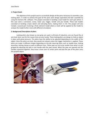
2. Background/ Description of pliers
Locking pliers also known as vise grips are used in all kinds of industries, one can found the at
any local store, just for the reason that are very handy. These locking pliers are design to hold an object
in place with great pressure. This pliers have the ability to be adjusted depending on the width of the
object. Once the pliers are lock, they would not release unless the trigger mechanism is applied. These
pliers are made in different shapes depending on the job requiring them such as needle-nose, locking
wrenches, locking clamps as well as different sizes. These jaws are set to be smaller than what is to be
gripped by adjusting the bolt in one handle with the jaws closed. When the jaws are opened and the
handles squeezed together, they move a lever over its center point and lock the jaw of the pliers onto
the gripped object.
2. Jose Olvera
2
3-a Connector
step 1) The sketch was drawn and dimensions were entered using the x,y plane.
step 2) Extrude was performed with a value of 3/16.
3. Jose Olvera
3
3-b Screw
step 1) A new sketch was drawn into the z and x axis
step2) The revolve function was applied using the z axis as reference
4. Jose Olvera
4
3-c Lower Jaw:
Step1) In order to create the lower jaw handle it was necessary to first to create a sketch which involved
making the outline of the jaw with the dimensions given in the power point. This procedure was
performed by taking the y axis and making it as a reference. From there, dimmensions were added to
the line in order to achieve one face of the jaw. The creation of circles were also necessary in this sketch.
Once the circles were made the opposite side from the teeth of the jaw was created. This step was
critical since the lines had to be tangent to the lines of the circle. Once the overall sketch was finish, the
trim function was utilize to erase excess lines in the sketch.
Step2)When sketch 1 of the lower jaw handle was done, the extrude of this sketch was performed. This
was done by putting symmetric value of 1/4 inch from the Y axis.
5. Jose Olvera
5
Step 3) After the dimensions were added to the extrude, sketch #2 was introduced. This new sketch
involved the bottom part of the jaw. The Critical part of this sketch was to make the bottom two line
parallel to the lines from sketch 1.
step 4) Extrude of sketch 2 was performed with a symmetric value from the y axis
6. Jose Olvera
6
step 5) This step was performed to unite the previous two extrudes into one solid piece. In this step the
edge blend of the bottom piece was added for each end.
step 6) A new sketch was created in order to create the teeth of the jaw. During this step the teeth were
created by making a curve line and making triangular line following the curved line. The offset function
was necessary to duplicate the curved line and move it to left side of the teeth. Finally the fillet function
was used in the top left part of the sketch to give jaw a small curved detail to it.
7. Jose Olvera
7
step 7) The extrude of the teeth figure was applied with a symmetric value of 1/4 inches.
step 8) The edge blend function was applied to the bottom portion of the teeth extrude. This also caould
have been performed with the skillet function before extruding the figure.
8. Jose Olvera
8
step 9) Another extrude was necessary to achieve the cut of the blade. It was not necessary to create a
new sketch, instead the extrude function was used. A rectangle sketch was needed and subtracted from
the extrude from the y axis. This will only subtract the extrude from one side, therefore the mirror
feature was used in order to duplicate the same subtraction from the opposite side.
9. Jose Olvera
9
Step 10) During this step the "unite" function was used to unite the teeth sketch with the rest of the
body. This created the final solid body of the lower jaw.
step 11) Finally the chamfer function was used to achieve the sharp edges of the blade. The chamfer
function was given a symmetric value achieving a sharp edge in both sides.
10. Jose Olvera
10
3-d Trigger
step1) A datum was created in the z,y plane following by a new sketch.
step 2) New datum was created in the z,y direction and a new sketch was entered.
11. Jose Olvera
11
step 3) New datum was created in the z,y direction and a new sketch was entered
step 4) New datum was created in the z,y direction and a new sketch was entered
12. Jose Olvera
12
step5) New datum was created in the z,y direction and a new sketch was entered
step 6) An arc was sketch in the y and x plane connecting the figures together as well as a rectangle
perpendicular to the arc.
13. Jose Olvera
13
step 7) The swept function was applied to the sketch with the "cubic" interpolation and alignment "by
points" options active.
step 8) Extrude was performed in order to subtract the circle made at the reference point
14. Jose Olvera
14
step 9) edge blend was applied to the bottom part of the trigger. This step was performed twice, one for
each side.
15. Jose Olvera
15
3-e Handle
step 1) A new sketch was introduced and drawn.
step 2) Extrude was performed and given a symmetric value of 1/2 inches.
16. Jose Olvera
16
Step3) A new datum plane in the y,z plane was introduced in order to create a new sketch of the inner
side of the handle. It was also extrude and given a symmetric value.
step4) The trim body function was applied to trim the excess body from step 2. This trim was applied to
both sides of the body
17. Jose Olvera
17
step 5) The shell function was applied. The shell was necessary in order to make the body hollowed
18. Jose Olvera
18
step 6) Extrude subtraction of the holes was performed.
step 7) A new sketch in the x and y plane was added for the bottom piece of the handle. In this step the
extrude was done for both sides with respect of the y axis. The trim body function was also applied in
order to erase the excess body of the extrude.
20. Jose Olvera
20
step 8) During this step the back piece of the handle part was missing. In order to obtain this part, an
extrude was performed by using the sketch in step 7 and selecting the option of "single lines". Once
this was achieved, the unite function was applied to convert all the bodies into one.
Step 9) The Edge blend feature was added the edges of the body
21. Jose Olvera
21
3-f Jaw Handle
step 1) This Step was critical, adjustments were made to the lower jaw handle in order to achieve this
sketch. From the lower jaw handle, the bottom parameters and dimensions where erased, leaving just
the top portion of the ketch to be used. The diameter was adjusted as well as the chamfer, which in this
case was removed, leaving a just a flat surfaced.
step 2) Extrude operation was applied with a symmetry value
22. Jose Olvera
22
step 3) The Boolean operation was performed and the subtract function was done to the figure. Also the
unite function was applied.
step 4) A new Datum coordinate system was created. In order to achieve this step reference lines were
need to represent each axis (y,x).
23. Jose Olvera
23
step 5) Three Datum planes were inserted into the new Datum coordinate system
step 5) Sketches were entered into the Datum planes using the rectangle function, arc function and
profile function. The offset function was used as a shortcut to duplicate the outer rectangle.
24. Jose Olvera
24
step 6) The arc function was used to connect the figures from the top and bottom.
step 7) Next, the swept operation was applied to the inner rectangles. The cubic interpolation and
alignment by points parameters where selected.
25. Jose Olvera
25
step 8) The same procedure of step 7 was performed to the outer rectangles.
step 9) Three Datum planes were inserted using the Datum coordinate system as a reference.
26. Jose Olvera
26
step 10) Sketches were inserted In each Datum plane using the profile tool, rectangle and arc funtion.
step 11) A line was drawn to connect the outer shields constructed in step 10. Also, the mirror feature
was applied to duplicate this line in the opposite side.
27. Jose Olvera
27
step 12) A line along with an arc was inserted in order to connect the four sketches in the outer shell.
step 13) The swept function was applied with the cubic interpolation and parameter alignment selected.
28. Jose Olvera
28
step 14) A line was created, connecting the first two sketches in the inner shell. An arc was added
connecting the third sketch.
step 15) The swept function was performed
29. Jose Olvera
29
step 16) An arc was added and extruded
step 17) Once the extrude was performed, the trim function applied
30. Jose Olvera
30
step 18) The Boolean unite and subtraction were used to finalize the figure.
step 19) The trim function was applied to take out the excess lines and Boolean subtract function was
applied for the center hole.
31. Jose Olvera
31
step 20) Extrude was applied to the last plane
step 21) The conic edge blend function was applied.
32. Jose Olvera
32
step 22) The simple hole was performed into the extrude using the Boolean subtraction
Step 23) finally the last step is to unite the solid figures.
33. Jose Olvera
33
4. Solid Model Assembly
Step 1) open a new model and select assmebly. Add the components in this case handle and
lower jaw. First select the lower jaw and insert. Insert handle and insert by constrain. Insert Fit and
touch constraint for handle and lower jaw.
Step 2) Add trigger, to the assembly and select absolute origin. Objects may be move by right
click and selecting " move object". The next step is to select a fit constrain between the handle hole and
trigger hole.
34. Jose Olvera
34
Step 3) Add jaw handle with the absolute origin selected, insert fit constraint between lower jaw
and jaw handle as well as distance constraint. The inserted part must me moved around to achieve the
right connection.
step 4) Insert connector with a fit constraint between the handle and connector. It is necessary
to insert a distance constraint between the connector and handle.
35. Jose Olvera
35
step 5) Insert crew with the absolute origin selected. Insert a fit, align constraint between jaw handle
and screw. Also a touch constraint needs to be added between the screw and connector. A distance
constraint is also needed for the screw and jaw handle. Finally a fix constraint may be needed to hold in
place for the jaw handle.
5. Summary
The software Siemens NX provides tools which are necessary to build and analyze Cad models.
In this project, NX has provided all the necessary tools such as extruding, revolving, swept, etc. which
are very useful way to build each individual part with precision. Each part made in this project had a
different level of difficulty such as the connector, screw were fairly easy to build just by simple steps
(sketching, extruding and revolving). Compared to the handle and lower jaw where swept, Boolean
functions and blend were necessary to complete these parts. Over all, part of the NX software and it's
tools is now well understood and FEM model is yet to be learn for further more analysis and
undestanding.