FIB recipes for TEM and APT sample preparation
•Download as PPTX, PDF•
0 likes•313 views

1. This document provides recipes and step-by-step instructions for preparing TEM lamella and atom probe tomography (APT) samples using a focused ion beam (FIB). 2. The TEM lamella preparation involves patterning and trenching the area of interest, liftout of the sample using an omniprobe needle, mounting on a TEM grid, and thinning to electron transparency. 3. The APT sample preparation similarly uses the FIB to pattern platinum deposition, mill trenches, lift out a sample chunk, weld it to mounting posts, and shape it into a fine needle for analysis.

Recommended
More Related Content
What's hot
What's hot (20)
Similar to FIB recipes for TEM and APT sample preparation
Similar to FIB recipes for TEM and APT sample preparation (20)
Recently uploaded
Recently uploaded (20)
FIB recipes for TEM and APT sample preparation
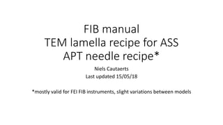
- 1. FIB manual TEM lamella recipe for ASS APT needle recipe* Niels Cautaerts Last updated 15/05/18 *mostly valid for FEI FIB instruments, slight variations between models
- 2. Geometry inside the FIB E - beam Ga - beam 52 ° Stage Eucentric height 7 or 10 mm (depends on FIB model)
- 3. Preliminary steps 1. Install the specimen • Vent the chamber. • Follow the loading procedure. Make sure grids and/or Si needle pads are also installed. • Pump the chamber. 2. Starting the session & E-beam alignment • Wait for good vacuum (Threshold?). • Beam control > WAKE UP on both the E and I beams. • Warm up the Pt-Gas heater (in patterning). This can take 10 min or more. • Select the right acceleration voltage and current for the E-beam. • Start viewing with the E-beam. • Move to the specimen where you will perform FIB work. • Go to 2k magnification or above. Focus the image. Click the “Link working distance with Z” button. Then move the specimen to eucentric height with Z movement. The specimen should remain in focus. • Go to 10k magnification or above and adjust beam astigmatism.
- 4. Preliminary steps 3. Eucentric height adjustment • Make sure beam tilts are zero’d • Focus the AOI at 3500x or above • Make sure that Z-Y linking is checked off and Eucentric is checked on. • Tilt the sample 5-10°. Adjust the stage with Z so that what was initially in the center of the viewing screen is again centered • Work your way up to 52°. If the area in the center of the screen remains in the center between 0 and 52° tilt, the AOI is at eucentric height. • Watch out when you tilt to 52° that you don’t touch the pole pieces with the stage. This is especially dangerous when working with tall samples. A 180° stage rotation may make your desired tilt possible. !!!Every time you make a major movement, the eucentric height alignment should be redone!!! In a well aligned FIB, eucentric height should coincide with the crossover point of the E and I beams.
- 5. Preliminary steps 4. Ion beam set-up • Switch your control to the ion beam by selecting that view window • Reset beam shift (Stage > Zero beam shift) • Select 10-30 pA current for viewing • Focus the Ion beam image - this should not have to be done often! !!!Every time you switch voltage or current on the ion beam, the image will shift and focus will be different. Correct this with beam shift and focus respectively. Don’t move the stage based on the ion beam image!!!
- 6. TEM lamella preparation recipe This recipe has been shown to work reasonably well for making TEM samples from ion irradiated austenitic steel. Milling steps may need to be adjusted depending on your material.
- 7. Patterning and trenching • Choose an AOI and go to eucentric height (see earlier) • Go to 52° tilt. Make the pattern on the right in the indicated order. • Insert the GIS for the first step. Retract for continuing to the trenching step! • Do the cleaning cross sections at 53.5 and 50.5° for front (lower) and back (higher) respectively. 1) Pt-dep, 15x2x2 µm, 30 kv, 0.3 nA 2) RCS, 20x10x15 µm, 30 kv, 15 nA 2) RCS, 20x10x15 µm, 30 kv, 15 nA 3) CCS, variable, 30 kv, 3 nA 3) CCS, variable, 30 kv, 3 nA
- 8. Liftout • Tilt to 0°. Make a J-cut on the lamella. Getting the pattern is easiest if you click in the help file. • Bring the easylift needle to park position. Insert GIS. Manouvre needle down and attach to the side of the specimen. • Cut the lamella loose. Currents are given on the right. • Lift the specimen out slowly. Retract the GIS. Then retract the easylift needle. 1) CCS, variable, 30 kv, 3 nA 2) Pt-dep 1.5x1.5x? µm, 30 kv, 50 pA 3) CCS, variable, 30 kv, 3 nA
- 9. Preparation of the grid and mounting • Go to the TEM grids. Bring one of the posts to eucentric height. Best is the tip where the sample will be mounted. Prepare the tip as seen on the right. • If the grid is not pre-tilted, do the milling at 0°. • If the grid is pre-tilted, also do the milling at 0° but rotate the stage 180°. • Insert the easilift to park. Insert the GIS. Bring the sample to the post and weld it on. Then cut the easylift loose. • If the grid is not pre-tilted, do all this at 0 ° tilt. • If the grid is pre-tilted, rotate the stage 180 ° and tilt 52° 1) Regular, 10x15x20 µm, 30 kv, 30 nA 2) Regular, variable, 30 kv, 30 nA 1) Regular, variable, 30 kv, 1 nA 2) Pt-dep variablex? µm, 30 kv, 0.1-0.3 nA
- 10. Thinning and cleaning • Tilt the stage such that the sample is aligned with the ion beam • For non-pre-tilted this is 52 °. The stage can be rotated 180 °. • For pre-tilted this is only 0 °. Only one configuration works. • Tilt a bit back and forth to thin the specimen on both sides. Higher angles are for doing the front. Smaller angles are for doing the back. • For the cleaning at low voltage, use a regular rectangle to mill for ~1 min over the whole specimen. 5 kV can still be used to thin the specimen further, but it should already be quite thin after the 30 kV, 50 pA step. kV Current Angle (°) Thickness 30 1 nA ±2.5 800 nm 30 0.5 nA ±2.5 400 nm 30 0.1 nA ±2 150 nm 30 50 pA ±1 <100 nm 5 48 pA ±3.5 2 27 pA ±5
- 11. APT sample preparation recipe This recipe has been shown to work reasonably well for making APT tips out of ion irradiated austenitic steel. Milling steps may need to be adjusted depending on your material.
- 12. 1. Pt patterning Instructions • Tilt stage to 52° • Draw a Pt-dep box (15 µm wide, 2 µm high, 0.3 µm thick) • Set ion voltage to 30 kV, current to 0.1 nA. Take a snapshot and make necessary focus and shift adjustments. • Insert Pt GIS needle • Start patterning (“Play” button) • When done, retract the GIS. Set I-beam current to 30 pA and take an image to check the deposit. • Delete the Pt-dep pattern. Stage configuration I-beam 52 ° 15 2 View diagram
- 13. 2. Milling Instructions • Tilt the stage to 22 ° • Draw a cross-section pattern (22 µm wide, 3.5 µm high, 3-5 µm deep). Change type to “Si”. • Set scan direction so the thick line is at the bottom. Move it so it is just slightly above the Pt deposit (the image is rotated 180 °, you will actually mill below the deposit). • Set beam current to 7-15 nA. Take snapshot and adjust the pattern location or beam shift/focus. • Start patterning. • Delete the pattern Stage configuration View diagram I-beam 22 ° 30 ° Pt 22 3.5
- 14. 3. Cleaning Instructions • Draw a cleaning cross section over the milled area. Change type to “Si”. • Adjust the scan direction so the thick line is at the bottom. • Set the beam current to 3 nA. Take snapshot and adjust pattern location. • Start patterning. Check occasionally on progress with snapshot. • Delete the pattern. Stage configuration View diagram I-beam 22 ° 30 ° Pt 22 2-3
- 15. 3. Final preparation of lift-out bar Instructions • Tilt the stage back to 0°. Rotate the stage by 180°. Use eucentric rotation. Find the AOI back and check eucentric height. • Repeat steps 2-3 (milling and cleaning) using this configuration. You should now have an equilateral triangle prism supported on two sides by the bulk. • Make a small cut on the left hand side. Use 3 nA beam current, “Si”, 3 micron depth. The bar will then be ready to weld to the omniprobe. • Tilt the stage back to 0°. For all omniprobe work the stage should not be tilted. Stage configuration View diagram I-beam 22 ° 30 ° Pt Sample 180 ° Sample
- 16. 4. Sample lift out Instructions • Make double sure you are at eucentric height. The omniprobe can crash into the sample if you deviate 100 micron. • Set ion beam current to 30 pA for viewing. • Insert Pt-GIS and then insert the omniprobe. • Move tip to park position. Then move it with X, Y and Z until the needle (almost) touches the bar near the left hand side. Use both the E and I-beams alternatingly. You can spot near-contact when a “shadow” appears below the needle. • Weld the bar onto the needle using 50 pA I-current. Pattern thickness of 0.5-1 µm thick should suffice. Don’t pattern too much on the needle – it is wasted. • Cut the bar loose on the other side (3 nA, “Si”, 3 µm deep). • Lift out the specimen with Z, then move to park position, then retract omniprobe. • Retract the Pt-GIS. View diagrams Pt Electron beam view Pt Ion beam view Welding Pt Ion beam view Cuting Pt Ion beam view Lift-out
- 17. 5. Welding to Si coupon Instructions • Move to the Si coupon and to the first tip where you want to place a needle. Bring this tip to eucentric height. • Insert the GIS and Omniprobe again. Move to park position. Maneuver with the Omniprobe so that the bar is directly over the coupon tip. Use both the I and E beam to adjust. • Weld the bar to the needle (50 pA I-current,1 µm thick ) • Cut the welded part loose (3 nA, “Si”, 3 µm deep). Don’t make cut too wide. • Move the Omniprobe up to a safe distance. Move the stage to the next needle. Repeat welding, cutting and moving to a new tip until the bar is finished. You should be able to create 5-6 welded chunks. • Retract Omniprobe and GIS. • Rotate the stage 180°. Check Eucentric height. Re-insert GIS. • Weld all the chuncks on the other side as well using the same settings. You can check the quality of your welds by rotating the stage to 90 °. View diagrams Pt Ion beam view - Welding Pt Ion beam view -Cutting @ 90° stage rotation Ion beam view
- 18. 6. Shaping the needles Instructions View diagrams • Make sure GIS and Omniprobe are retracted. Make sure you have one of the chuncks on eucentric height. • Rotate the stage to 90°. Tilt stage to 52° • Draw an annular milling (“Si”) pattern and center it over the chunk. Make the scan direction so that the thick line is in the center. Use the settings in the table. In each step make the pattern smaller and lower current and voltage to obtain a very fine needle. • Make sure you center your pattern each time you change current or voltage – the image in the ion view will shift. At low voltages it will be hard to focus the ion image. • Check the progress of your needle in the E-beam image. For ion irradiated specimens it is important not to mill too much away from the top of the specimen • After all the steps in the table are complete, take a good image of the needle with the E-beam. You will need this for the APT reconstruction (measuring tip radius) • Repeat this for all the chunks on the coupon. • Store your needles in vacuum as much as possible. Voltage (kV) Current Outer diameter (micron) Inner diameter (micron) Depth/Z (micron) 30 3 nA 6 4 0.3 30 1 nA 4.5 2 0.3 30 0.3 nA 4 1.5 0.2 30 0.3 nA 3.5 1 0.2 30 0.1 nA 3 0.75 0.2 30 0.1 nA 2.5 0.5 0.1 30 30 pA 2 0.25 0.1 5 48 pA 2 0 Watch shape on E-beam 2 27 pA 2 0 Such that it lasts about 2 min Stage configuration Sample 90 ° I-beam 52 ° E-beam I-beam