The document is a chapter about Ethernet from an introduction to networks guide. It discusses Ethernet protocols, LAN switches, and the Address Resolution Protocol (ARP). The key points are:
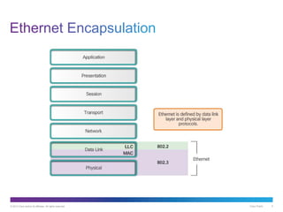
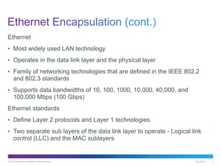
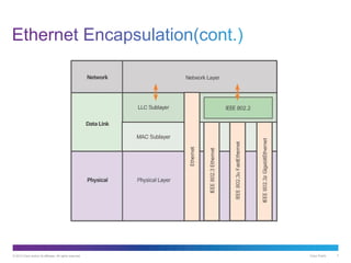
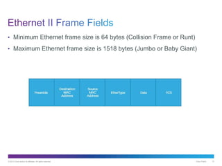
- Ethernet is the most widely used LAN technology and operates at layers 1-2 of the OSI model.
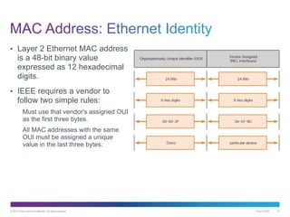
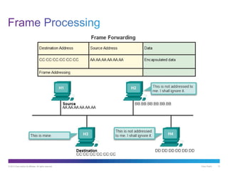
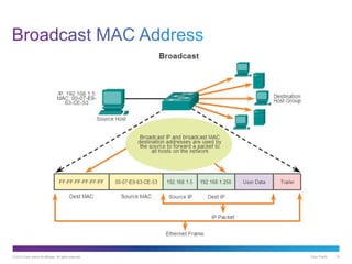
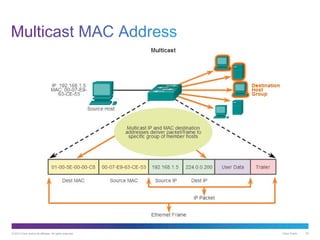
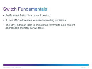
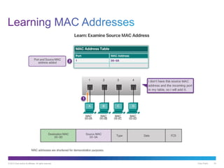
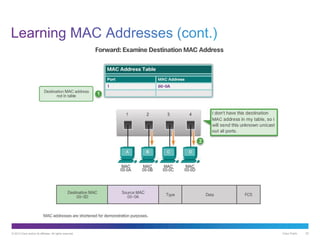
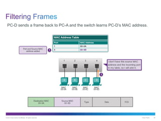
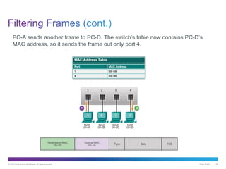
- Switches use MAC address tables to forward Ethernet frames and learn addresses of connected devices.
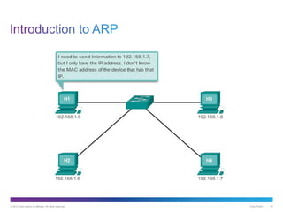
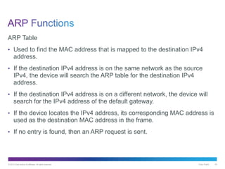
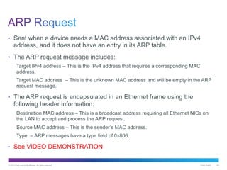
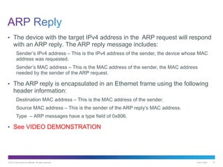
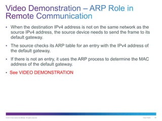
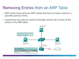
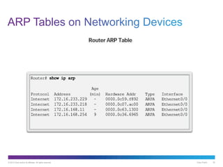
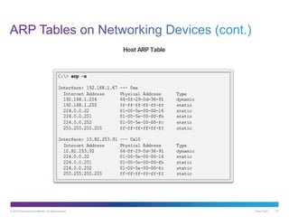
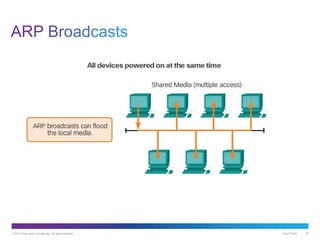
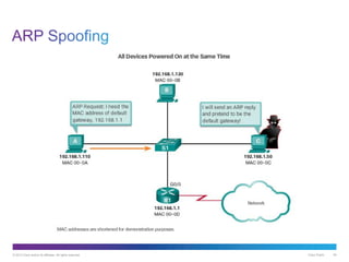
- ARP converts between IP addresses and MAC addresses, allowing communication on a network. ARP requests are broadcast to resolve addresses not in the local ARP table.