This document describes the design of an irregular counter sequence using 4 flip-flops. It involves the following steps:
1) Converting the decimal sequence into binary.
2) Determining 4 flip-flops are needed to represent the maximum value of 8.
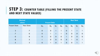
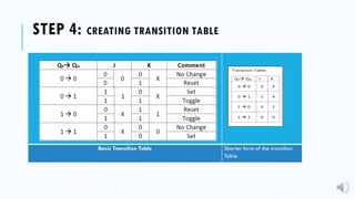
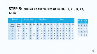
3) Creating a counter table to determine the present and next state binary values.
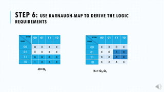
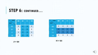
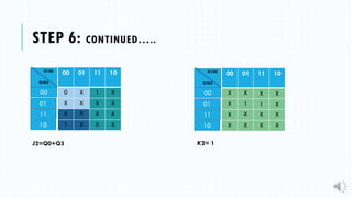
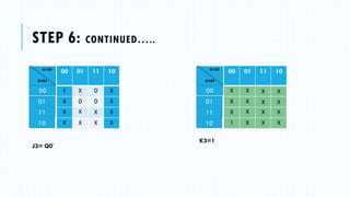
4) Deriving the logic equations using Karnaugh maps.
5) Connecting the flip-flops and generating the circuit diagram based on the logic equations.