Download to read offline
![International Research Journal of Engineering and Technology (IRJET) e-ISSN: 2395-0056
Volume: 05 Issue: 06 | June 2018 www.irjet.net p-ISSN: 2395-0072
© 2018, IRJET | Impact Factor value: 7.211 | ISO 9001:2008 Certified Journal | Page 2805
A STANDALONE SOLAR SYSTEM
Prajit Goswami 1, Abhishika Baruah 2, Mr. Tilok Baruah3
1Lecturer, Electrical Engineering Department, POWIET, Jorhat, Assam, India
2Master degree student, Instrumentation and Control Engineering Department, Jorhat Engineering College, Assam,
3Assistant Professor, Jorhat Engineering College, Jorhat, Assam.
---------------------------------------------------------------------***---------------------------------------------------------------------
Abstract - Energy crisis has become a serious issue for the
developing countries across Asia and Africa, nowadays.
Compared to the other developing countries, India has a
greater demand for power since it is the country with the
second highest population in the world. This might be an
alarming indication that our present existingenergyresources
are starting to run out, which has very serious and disturbing
consequences on the global quality of life as well as the global
economy. Therefore, we have tried to access the theoretical
and technical viability of a standalone PV (photovoltaic)
system for base stations located in areas where it is not
efficient to run power transmission lines or have alternative
generation like diesel generator. This paper aims to work out
on optimum sizing of the standalone PV system for BTS in
rural area having a fixed D.C load.
Key Words: base-transceiver system (BTS), non-
conventional energy source, photovoltaic system, solar
panel
1. INTRODUCTION
Energy saving is a key focusfor the Indian Telecom Industry
today. This is especially true in rural areas where energy
consumption contributes to 70% of the total network
operating costs (OPEX). In urban areas, the energy costs for
network operating ranges between 15-30% [1]. It is
estimated that in India almost 70% of telecom towers are
located in areas with more than eight hours of grid outage
and almost 20% are located in off-grid areas.[2] This
uncertainty in power has compelled the providers to use
diesel generators to ensure a continuous supply of power.
Annually more than 2.6 billion litresof diesel is consumedto
operate telecom towers, resulting in the emission of 7
million metric tons of CO2. Given the deregulation of diesel
prices and the need to reduce CO2 emission, it has become
imperative for the industry to evaluate all alternative
options in order to improve network operations and to
reduce energy costs. The best way to harvest the sun’s
power is the photovoltaic technology. Stand alone
photovoltaic system is a way to electrify remoteareas,giving
power to BTS (base-transceiver system) stations and
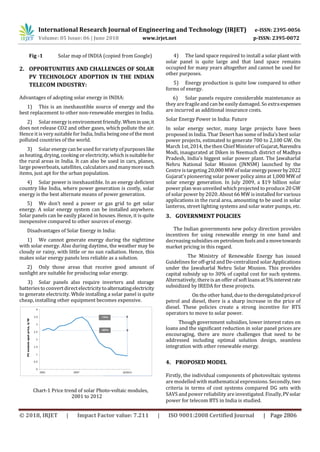
increasing trend in rise in prices of petroleum products.
India, with its excellent irradiance has the opportunity to
exploit PV solar power to meet the challenges coming from
the DG sets of onsite power generation. Coupled with a
battery back-up i.e. Stand-alone PV system are a viable
exciting alternative to reduce the correlationbetweenpower
costs and total operating expenditures, thereby providing
sustainable and reliable strategic solution to the fuel
problem. While the capital expenditure (CAPEX) to
implement a PV system is greater than setting up DG sets,
this is more than offset through a reduction in operating
expenditure (OPEX).
The table given below providesfacts about solar radiationin
India-
Table-1: Parameters and their availability in INDIA](https://image.slidesharecdn.com/irjet-v5i6525-180817070025/85/IRJET-A-Standalone-Solar-System-1-320.jpg)
![International Research Journal of Engineering and Technology (IRJET) e-ISSN: 2395-0056
Volume: 05 Issue: 06 | June 2018 www.irjet.net p-ISSN: 2395-0072
© 2018, IRJET | Impact Factor value: 7.211 | ISO 9001:2008 Certified Journal | Page 2808
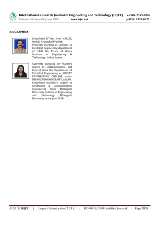
To calculate the design operating voltage for each module
and acceptable module output current, Siemens solar m55
modules are used.
Chart -1 SpecificationofSiemenssolarm55modules
From the Siemens solar M55 modules specification, the
maximum power voltage at STC = 17.4 Volts.
So, the desired operating voltage of each module = 17.4 X
0.85 (Depth of discharge allowable)
= 14.80 Volts
From the manufacturer’s data sheet shows the nominal
power output at 1000W/m2 and 25°C is 53.0 Watts.
Therefore, the guaranteed power output =53.0X90%=47.7
Peak sun hours for the proposed location in December is 3.8
hours. The amount of energy produced by the array per day
during the worst month is determined by multiplying the
selected PV power output at STC by the peak sun hours at
design tilt = 47.7 X 3.8 = 181 Whr. Also, A de-rating factor
0.90 (for moderate climate and non- critical application) is
used in this application to determine the module energy
output at operating temperature. Multiplying the de-rating
factor by the energy output module establishes an average
energy out from one module = 0.90 X 181 Whr = 163 Whr.
Again, Dividing the required output per day by the module
energy output at operating temperature determines the
number of modules required to meet the energy
requirements = 1133 KWh/163 Whr = 113,000/163 = 693
modules. Dividing battery bus voltage by module design
operating voltage 48 Volts/14.8 = 3.24 = 4 (round to next
higher integer). Therefore, Number of strings in parallel =
693/4 = 173.25 = 174.
Number of modules to be purchased:- 174 X 4 = 696
modules. This rated module output in watts as stated by the
manufacturers. PV modules are usual priced in terms of the
rated module output. The Siemen solar M55’s rated module
power is 53. Finally, multiplying the number of modules to
be purchased by nominal rated module output determines
the nominal rated array output = 696 modules X 53 Watts =
36.888 Kw
5. CONCLUSION
Stand alone photo-voltaic system is recognized a viable
solution to energiesrural off- grid applications.Inthispaper,
we have tried to summarize the optimal sizing ofstandalone
PV system for a given telecom application (BTS), also,
reviewing the mathematical model of a cell, a module and a
PV array for a BTS load (D.C) located in remote and hilly
area.
FUTURE SCOPE
The work discussed in this paper may be extended to BTS
site at remote areashaving A.C loadsalong withD.C loadsby
introducing a proper sized inverter. Furthermore, a hybrid
system comprising a diesel- generator set with the existing
stand-alone system may be a suggestion for better
performance of the desired load.
REFERENCES
[1] Adoption of Green Technology and Safety of Wireless
Network by Milan Jain (Sr. Research Eng. – Converged
Network, TRAI)
[2] http://www. Gsma.com/ mobile for development/ wp-
content/uploads/2012/05/ Energy- for-the-Telecom-
Towers- India market-Sizing- and– Forecasting-
September – 2010.pdf.
[3] Kashif I., Zainal S., An improved Modeling method to
Determine the Model Parameters of Photovoltaic(PV)
Modules Using Differential Evolution (DE), Science-
Direct, Solar Energy, Elsevier Ltd., 2011,85, P.2349-
2359.
[4] Pandiarajan N., Ranganath M., “Mathematical Modeling
of Photovoltaic Module with Simulink,” at 1st
International Conference on Electrical System
(ICEES),2011, P. 258-263.
[5] Meier D.L., Good E.A., Chandrasekharan V., Determining
Componentsof SeriesResistance from Measurementon
A Finished Cell, Photovoltaic Energy Conversion , IEEE
4th World Conference on PV Energy Conversion,2006 ,
2,P. 1315-1318.
[6] Marsha Far hat, “Advanced Fuzzy MPPT Control
Algorithm for Photovoltaic Systems,” Science Academy
Transactions on Renewable Energy Systems
Engineering and Technology Vol.1, No.1, March
2011,United Kingdom.](https://image.slidesharecdn.com/irjet-v5i6525-180817070025/85/IRJET-A-Standalone-Solar-System-4-320.jpg)

The document discusses the viability of using standalone solar photovoltaic (PV) systems to power base transceiver stations (BTS) in rural areas of India where grid connectivity is limited. It notes that over 70% of telecom towers currently rely on diesel generators due to grid outages. Standalone PV systems could provide a more sustainable and cost-effective alternative. The document outlines the components and optimal sizing methodology for standalone PV systems powering BTS stations. It also discusses factors like solar radiation levels and government policies in India that encourage the use of solar energy.